1
Advanced Design System 1.5
Bluetooth DesignGuide
March 2001
Notice
The information contained in this document is subject to change without notice.
Agilent Technologies makes no warranty of any kind with regard to this material,
including, but not limited to, the implied warranties of merchantability and fitness
for a particular purpose. Agilent Technologies shall not be liable for errors contained
herein or for incidental or consequential damages in connection with the furnishing,
performance, or use of this material.
Warranty
A copy of the specific warranty terms that apply to this software product is available
upon request from your Agilent Technologies representative.
Restricted Rights Legend
Use, duplication or disclosure by the U. S. Government is subject to restrictions as set
forth in subparagraph (c) (1) (ii) of the Rights in Technical Data and Computer
Software clause at DFARS 252.227-7013 for DoD agencies, and subparagraphs (c) (1)
and (c) (2) of the Commercial Computer Software Restricted Rights clause at FAR
52.227-19 for other agencies.
Agilent Technologies
395 Page Mill Road
Palo Alto, CA 94304 U.S.A.
Copyright © 2001, Agilent Technologies. All Rights Reserved.
ii
Bluetooth DesignGuide
1
2
Bluetooth DesignGuide QuickStart
Using the DesignGuide.............................................................................................
The DesignGuide Menu......................................................................................
Displaying Simulation Data.......................................................................................
Interactive Simulations .......................................................................................
1-2
1-3
1-3
1-4
Bluetooth DesignGuide Reference
Where Do I Start?..................................................................................................... 2-2
Basic System Test Benches ............................................................................... 2-3
VCO/PLL (Phase Locked Loop) Investigations .................................................. 2-7
Component/Subnetwork Evaluations ....................................................................... 2-9
Channel Filter Impulse Response (TEST_FILTER_IMPULSE.dsn) ................... 2-9
Channel Filter Swept Response (TEST_FILTER_COMPLEX.dsn) .................... 2-9
FM Demodulator Selection (TEST_LOWIF_FMDEMOD) .................................. 2-10
Multipath Propagation Test Benches ........................................................................ 2-12
Multipath Impulse Response (TEST_MULTIPATH_IMPULSE)........................... 2-12
BER/Outage w/MPath, Noise, No Chan. Filter (TEST_MULTIPATH_BER_NOFILT)2-14
System Compliance Tests ........................................................................................ 2-16
Catalog of Test Benches and Subnetworks.............................................................. 2-18
Test Benches ...................................................................................................... 2-18
Subnetworks....................................................................................................... 2-22
iii
iv
Chapter 1: Bluetooth DesignGuide
QuickStart
The Bluetooth QuickStart Guide provides an introduction to the content and use of
the Bluetooth DesignGuide. It contains:
• A brief description
• Section on using the DesignGuide
• Section on displaying simulation data
For detailed reference information, refer to Chapter 2, Bluetooth DesignGuide
Reference.
The Bluetooth DesignGuide is an application package for the Agilent Advanced
Design System (ADS), which contains various system test benches and reference
designs (for example, an optimal low-IF receiver) for the RF portion of the Bluetooth
physical layer. Briefly, it allows for the investigation of system performance (from
simple EYE diagrams to BER, the ultimate test) when there are present impairments
such as AWGN (Gaussian noise), VCO phase noise, multipath, and/or co-channel /
adjacent-channel / intermodulation / pulsed-RF interference. In many cases, the
receiver's EYE diagram may be observed in real time during the simulation, while
the level of the signal or interferer is adjusted via an interactive slider.
In addition, the DesignGuide addresses some PLL/VCO design issues and helps you
select the best demodulator for your receiver. All of these applications are easily
accessed via a menu-type user-interface that is integrated with ADS when the
DesignGuide is installed.
1-1
Bluetooth DesignGuide QuickStart
Using the DesignGuide
The Bluetooth DesignGuide adds a menu selection to each ADS Schematic window
under DesignGuides, which provides convenient access to test benches, subnetworks
and data displays. It may be installed by itself, or may be installed along with other
DesignGuides.
1-2
Using the DesignGuide
The DesignGuide Menu
All of the DesignGuide contents are accessed using the Bluetooth DesignGuide menu
found under the DesignGuide pull-down on any schematic window. The contents have
been divided into several categories:
• Basic System Test Benches. Tutorial simulations to help you understand the
Bluetooth RF segment and to evaluate some filtering options for the
transmitter
• Component/Subnetwork Evaluations. Simulations to help you understand and
validate many of the built-in subnetworks used in the system test benches
• VCO/Phase-Locked-Loop(PLL) Investigations. Simulations of PLL topologies
which address timing and noise issues
• Multipath Propagation Test Benches. Simulations that include multipath models
for investigating system performance under non-ideal indoor propagation
conditions
• System Compliance Tests. System test benches for sensitivity and blocking
performance
From each category, move the cursor to the right to open the menu that displays the
available items. Each selection (except those named Display.... will open a top-level
test bench schematic and in many cases, a data display will also open.The Display....
selections will open additional data displays, but only after the test bench listed
above it has been opened. There are also menu selections to open this QuickStart
help, a User Manual and an About... box.
Displaying Simulation Data
Some test benches have real-time Tk displays that open by themselves each time a
simulation is performed. Other test benches will automatically open a Data Display
window when selected. In several instances, for example a test bench that is capable
of BER (Bit Error Rate) calculations, additional Data Displays are available. Access
them by selecting the Display..... options listed under the test bench item on the
menu, after the test bench has been opened.
Displaying Simulation Data
1-3
Bluetooth DesignGuide QuickStart
Interactive Simulations
Some of the simulations that use Tk displays also have interactive sliders that allow
a parameter to be adjusted during the simulation so the results can be immediately
observed. When you want to run a non-interactive simulation so that output data are
only collected by sinks, such as time-domain or spectrum measurements, all Tk items
should be de-activated. The subnetwork TkPowerControl should also be de-activated
and bypassed with a wire because it contains an interactive slider.
Interactive Slider
1-4
Displaying Simulation Data
Chapter 2: Bluetooth DesignGuide
Reference
The Bluetooth DesignGuide User Manual contains application guidelines for using
the test benches provided with the Bluetooth DesignGuide, including:
• Basic System Test Benches
• Component/Subnetwork Evaluations
• VCO/PLL (Phase Locked Loop) Investigations
• Multipath Propagation Test Benches
• System Compliance Tests
.For a useful reference list, refer to the section “Catalog of Test Benches and
Subnetworks” on page 2-18.
Note This manual assumes that you are familiar with all of the basic ADS program
operations. For additional information, refer to the ADS User’s Guide. For access to
the complete set of ADS online documents, select Help > Topics and Index from an
ADS program window.
2-1
Bluetooth DesignGuide Reference
Where Do I Start?
Your first steps depend on whether you are creating or integrating a design:
• Designing a Bluetooth solution: This DesignGuide provides a reference receiver
design that can be evaluated against measurements of your RF hardware and
simulations of an ADS model of that RF hardware. There are also other tools
that target specific components of the Bluetooth physical layer. It is suggested
that you review the Basic System Test Benches first, followed by the
Component/Subnetwork Evaluations (emphasizing filter selection). The
VCO/PLL segment may be useful if you are either designing a synthesized
source or need to optimize an existing design for good time-domain performance
and phase noise characteristics. Finally, the System Compliance Tests focus on
evaluating performance in the presence of interferers.
• Integrating a Bluetooth solution: For integrating into a product, such as another
wireless device, handset or any environment with other RF emitters, the
DesignGuide provides simulation-based tools for understanding system
performance under various conditions. It is suggested that you review the Basic
System Test Benches first, followed by the System Compliance Tests. The
Multipath Propagation Test Benches add the ability to model certain indoor
propagation conditions and observe the effect on the system’s performance.
In the following sections, some important Test Benches are discussed in detail.
2-2
Where Do I Start?
Basic System Test Benches
The basic system test benches provide an introduction to the Bluetooth RF interface.
Here, we will use them to discuss in detail some of the main components and
subnetworks used in the DesignGuide.
Ideal Transmit-Receive EYE Diagram (TEST_EYE.dsn)
This is a quick simulation to observe the eye diagram due to the combined effects of
the transmitter and the complete receiver. This system is built from only the most
basic components, starting with SHAPED_DATA. This component produces
Gaussian-filtered MSK data according to the Bluetooth specification. An optional
Preamble, which consists of the 10101010.....sequence may be included by setting
Preamble > 1.
Where Do I Start?
2-3
Bluetooth DesignGuide Reference
The output of SHAPED_DATA is input to an ideal ADS FM modulator component.
The TkPowerControl follows, which allows the signal level to be adjusted using an
interactive slider. The AWGN_CHANNEL adds thermal noise equal to -174 dBm/Hz
to the signal
.
The signal is bandpass-filtered and ideally demodulated.
2-4
Where Do I Start?
Interactive slider
After scaling and conversion to floating-point, the EYE diagram is displayed on a
TkPlot. In this simulation, SHAPED_DATA, TkPowerControl and AWGN_Channel
are subnetworks created for the Bluetooth DesignGuide.
Where Do I Start?
2-5
Bluetooth DesignGuide Reference
Transmit Spectrum (TEST_TX_SPECTRUM.dsn)
Summary This test bench is intended to illustrate some of the filtering options for
the Bluetooth transmitter. When the 8-bit FIR filter is used, images of the spectrum
are seen at intervals related to the sampling rate. However, these images are below
the phase noise sidebands and are hence adequately filtered out.
Additional analysis of the FIR filter may be found by selecting
Component/Subnetwork Evaluations > Transmit Filter (Gaussian FIR).
Images due to FIR Filter
2-6
Where Do I Start?
VCO/PLL (Phase Locked Loop) Investigations
In this category of Test Benches, a set of tools are provided to assist in the design and
optimization of signal sources for a Bluetooth implementation. These are intended as
basic tools that address some key performance requirements. For help with the full
PLL design flow, the PLL DesignGuide for ADS is available.
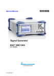
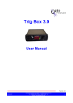
VCO Response to Frequency Step (TEST_PLL_TR)
This test bench demonstrates Bluetooth Fractional-N Synthesizer transient response
to an 80-MHz step. The VCO frequency is 2.4 GHz and the Reference frequency is 1
MHz. The output frequency is Fvco+N or 2.48 GHz. The loop bandwidth, fn, is 5 kHz.
This design, which is simulated under the Transient controller, uses the
VCO_DivideByN and PhaseFreqDet components. The PFD output is coupled to the
RC loop filter using the Voltage Controlled Current Source (VCCS). The frequency of
the source must settle to within +/- 20PPM in 200 usec. To understand how to
optimize the loop filter, select VCO Parameter Optimization.
.
Where Do I Start?
2-7
Bluetooth DesignGuide Reference
2-8
Where Do I Start?
Component/Subnetwork Evaluations
Following are details on designs demonstrating component/subnetwork evaluations.
Channel Filter Impulse Response (TEST_FILTER_IMPULSE.dsn)
Summary This test bench evaluates the impulse response of the Bessel filter used for
pulse shaping in the Bluetooth Receiver.
ADS has two main simulation modes: Analog/RF and DSP. This Test Bench compares
the impulse responses of the circuit (A/RF) and timed (DSP) models, which can be
very similar. The A/RF model has an advantage in that its group delay at the edge of
the passband may be controlled. However, using it in a DSP design requires
Transient cosimulation, which may be slower.
Channel Filter Swept Response (TEST_FILTER_COMPLEX.dsn)
Summary This test bench sweeps the complex receive filter model used in the Design
Guide (FILTER_CHEB_COMPLEX). Open Data Display TEST_FILTER_COMPLEX.
Note that the QAM_Demod is set for a Gain Imbalance of 0.5 dB and a Phase
Imbalance of 3 degrees. The data display compares the swept RF response to the
balanced condition.
Component/Subnetwork Evaluations
2-9
Bluetooth DesignGuide Reference
FM Demodulator Selection (TEST_LOWIF_FMDEMOD)
Summary An EYE diagram display allows for the relative performance of various
demodulators to be observed. Due to the different output levels and the amount of
residual DC for each demodulator, select View > View ALL on the Demod_TEST
TkPlot to see the EYE diagram.
2-10
Component/Subnetwork Evaluations
Demodulator selection is important when designing a Bluetooth solution because
receiver performance is often largely dependent upon the demodulator’s performance.
The DesignGuide provides a choice of several demodulators.
Activate one demodulator
at a time. Push into each
subnetwork to see it’s
structure.
Descriptions of each demodulator are available in the Catalog of subnetworks. The
DEMFM_BESS_MULT is notable for excellent performance. An additional test
bench, available under FM Demod Selection w/Channel Filter uses just a single
complex Chebyshev channel filter in the receiver, instead of the
high-pass/Chebyshev/limiter/Bessel signal path used in TEST_LOWIF_FMDEMOD.
This puts additional requirements on the demodulator in exchange for a simpler
signal path.
Component/Subnetwork Evaluations
2-11
Bluetooth DesignGuide Reference
Multipath Propagation Test Benches
Following are summaries of test benches used for multipath propogation.
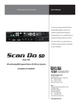
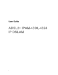
Multipath Impulse Response (TEST_MULTIPATH_IMPULSE)
Summary This test bench evaluates the MULTIPATH_EXPONENTIAL model using
an impulse input. The delay spread profile is shown in the associated data display.
Due to the use of a moving average over 512 symbols, the data display will require
several minutes to open (about 2 minutes for a PIII/650 under Windows NT). Select
Display Impulse Response after the schematic is displayed to show the data display
window.
Note The Multipath subnetwork requires a large memory space due to its
complexity. Performance will be reduced on systems having less than 256 MB of
RAM.
2-12
Multipath Propagation Test Benches
Tap coefficients for one burst (typical)
The Multipath_Exponential model implements an exponential power decay
multi-path channel model that is widely used for indoor propagation. The mean
excess delay and the tap delay can be specified in microseconds. Each tap coefficient
has a Rayleigh power distribution, and a uniform phase distribution. For a specified
value of time Tburst, the channel snapshot is kept fixed. For the next Tburst
duration, a new channel snapshot is taken. The tap coefficients for each snapshot are
available. The corresponding values of the RMS delay spread and the mean excess
delay are also available. TK plots for these measurements can also be enabled.
The tap coefficients are calculated by:
r = exp(-Delay_Tap/Mean_Delay)
a0 = 1/Mean_DelayDelay_Tap, a1= r*a0, a2 = r*a1,......, an = r*a(n-1)
Multipath Propagation Test Benches
2-13
Bluetooth DesignGuide Reference
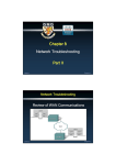
BER/Outage w/MPath, Noise, No Chan. Filter
(TEST_MULTIPATH_BER_NOFILT)
Summary This test bench calculates the BER without a channel filter, but with
multipath included. It will usually exhibit ideal BER because the C/N is large (the
transmit power is 0 dBm and no noise is included). The mean delay is larger than for
the other Multipath test benches, being set to 0.2 usec, and the tap delay is 0.05 usec.
To observed channel outage, activate SweepSeed to vary the random seed value used
by the Data Flow simulator. A channel with BER > 0.1% is considered to have caused
a failed burst transmission. The simulation time is about 120 seconds (with
ParameterSweeps deactivated), for 250 bits using a PIII/650 MHz under NT with 256
MB RAM. The simulation time will significantly increase if less than 256 MB of RAM
are available.
2-14
Multipath Propagation Test Benches
The preceding figure shows a portion of the output display for multipath (0.2 usec
delay setting) with no channel filter, at the output of the ideal FM demodulator. The
Clock Recovery action must accept this distorted input and re-synch the data. It
might be informative to vary this test bench by substituting other non-ideal
demodulators such as the subnetworks provided with the DesignGuide, and observe
their performance under multipath conditions.
Multipath Propagation Test Benches
2-15
Bluetooth DesignGuide Reference
System Compliance Tests
This category of test benches is intended to provide a convenient starting point for
validating a Bluetooth system. The tests are based on the Bluetooth Specification
version 1.0 B Radio Specification, Section 4, Receiver Characteristics and the RF Test
Specification v.0.9r7, section on C/I performance, and are summarized in Table 2-1.
Table 2-1. Interference Performance Requirements
Interferer Type
Interferer level P[dBc]
Wanted signal level,
P[dB]>reference sensitivity
Co-Channel interference, C/I
11 dB
10
Adjacent (1 MHz) interference, C/I
Adjacent (2 MHz) interference, C/I
Adjacent (1 MHz) interference, C/I
0 dB
-30 dB
-40 dB
10
10
3
Each test bench sets up a starting condition according to Table 2-1, and other
conditions might be easily specified. For example, the adjacent interferer offset can be
set to 1, 2, 3 or more MHz away from the wanted signal. An interactive slider
provides for attenuating the interfering signal while observing the EYE diagram. For
BER tests, the interactive slider is not used, and the appropriate components are
de-activated as described on the test bench. In addition to the Co-Channel and
Adjacent Channel tests, the following are also available:
• Combined Co-Channel/Adjacent Channel test
• Intermodulation test
• Pulsed Interferer with 2nd-order Intercept (IP2) Test Bench.
2-16
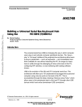
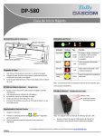
System Compliance Tests
From the Adjacent Channel
Interference/Blocking Test Bench:
“acr” sets the interferer’s relative power
“M” sets the frequency offset in MHz
“Prx” sets the wanted signal’s power
The preceding graphics show the EYE diagram and Control Panel for the Adjacent
Channel Interference Test Bench. Moving the slider to the left will attenuate the
interferer level.
System Compliance Tests
2-17
Bluetooth DesignGuide Reference
Catalog of Test Benches and Subnetworks
Following are details on the available test benches and subnetworks.
Test Benches
Following are details on the available test benches/
Basic System Test Benches
TEST_TX_SPECTRUM.dsn. The spectrum of the transmitter can be simulated here.
The effects of phase noise and Gaussian filter quantization can be observed, and
checked against the allowed spectral template for various standards.
TEST_EYE.dsn. This is a quick simulation to observe the eye diagram due to the
combined effects of the transmitter and the complete receiver.
TEST_TX_RX_EYE.dsn. The eye diagram corresponding to the detailed-model (full
Transmitter and lowIF-Receiver with phase noise and filters) end-to-end link can be
simulated in this design.
Component/Subnetwork Evaluations
SHAPED_DATA.dsn. This design models a two-level or four-level Gaussian filtered
data source. It includes an initial two-level training sequence.
SLICER.dsn. This design extracts the average level of the analog de-Modulated signal
and uses this level as the slicing reference to a comparator input. The incoming
analog signal is sliced into digital bits by the comparator. The slicer behavior is
depicted in the display SLICER.
TEST_CHANNEL_FILTER.dsn. The combined behavior of the high pass DC notch filters
and the complex channel filter is simulated in this design.
TEST_FILTER_COMPLEX.dsn. The complex channel filter behavior of his simulated in
this design.
TEST_FILTER_COMPLEX_TIME.dsn. The time domain response of the complex channel
filter is simulated here.
TEST_FILTER_IMPULSE.dsn. The impulse response of circuit level and system level
low pass Bessel filters are compared in this simulation. These low-pass Bessel filters
were used in the design of the band pass complex Bessel filter. The system level
2-18
Catalog of Test Benches and Subnetworks
model of the filter was preferred to speed up the simulation. However, it had to have
an impulse response that was identical to that of the circuit level filter model.
TEST_GAUSSIAN_FIR_FILTER.dsn. The Gaussian filter is implemented digitally as a
17-tap FIR filter with a the six bit word length for each tap. The impulse response of
the filter is simulated in this design. The impulse response is saved into a file. Data
from this file is then used to define the tap coefficients of an FIR filter. The display
TEST_GAUSSIAN_FIR_FILTER shows the impulse response.
TEST_LOWIF_FILTER_DEMOD.dsn. This test bench is used for comparing and
optimizing the combination of the channel filter along with various types of poly
phase FM Demodulators.
TEST_LOWIF_FMDEMOD.dsn This is similar to the
TEST_LOWIF_FILTER_DEMOD.dsn test bench. The effect of a poly phase harmonic
suppression band pass filter at the output of the hard limiters is investigated.
TEST_LOWIF_RECEIVER.dsn. This is similar to the
TEST_LOWIF_FILTER_DEMOD.dsn test bench. The complete receiver chain is
investigated.
VCO/PLL (Phase Locked Loop) Investigations
TEST_PLL_SS.dsn. The RF synthesizer reference frequency spurs due to charge pump
mismatch can be observed in this harmonic balance steady state simulation.
TEST_PLL_TR.dsn. The transient response of the RF synthesizer is simulated in this
test bench.
TEST_PLL_TR_linear.dsn. This is the main test bench for optimizing the RF
synthesizer parameters. The loop filter components are defined in terms of 2
parameters: z (related to damping constant) and fn (related to loop band with). The
various results are shown in displays beginning with the name
TEST_PLL_TR_linear.
Catalog of Test Benches and Subnetworks
2-19
Bluetooth DesignGuide Reference
Multipath Propagation Test Benches
TEST_MULTIPATH_ IMPULSE. The impulse response of the multi-path channel is
simulated in this design. The frequency response of the channel is obtained, with and
without averaging done over any given modulation bandwidth, e.g. 1 MHz for
Bluetooth. The results are shown in the display TEST_MULTIPATH_ IMPULSE. At
frequencies where there is a large relative channel loss without averaging, one can
expect severe intersymbol interference due to multi-path. It can also be seen that the
correlation bandwidth is approximately the inverse of the RMS delay spread.
TEST_MULTIPATH_POWER. Varies the channel snapshot, and measures the
corresponding Modulated signal average power at the output of the channel. The
corresponding RMS delay spread values are also available. The display
TEST_MULTIPATH_POWER_200_50_seed shows the simulation results for a 200 ns
delay spread using tap spacing of 50 ns. A large number of channel snapshots were
taken for the simulation. The pdf and cdf distributions of the multi-path loss are also
shown.
TEST_MULTIPATH_EYE. This shows the TK plot of the FM de-Modulated eye diagram
under multi-path conditions. The corresponding multi-path tap coefficients and RMS
delay spread values are also shown.
TEST_MULTIPATH_ EXPONENTIAL. This simulation shows the variations in both the
mean power and the instantaneous Modulated power for various channel snapshots,
along with the corresponding delay spreads.
TEST_MULTIPATH_BER. This simulation measures the BER for various channel
snapshots. It is useful for computing the channel outage when the signal to noise
ratio is large. See display TEST_MULTIPATH_BER for one particular channel
snapshot. It shows the eye diagram, the channel snapshot, the recovered and
transmitted bits, the BER, and the RMS delay spread. For channel outage
simulations, only the BER should be enabled and the seed and/or frequency varied
over a large number of points.
TEST_MULTIPATH_BER_AWGN. This performs simulations similar to that in
TEST_MULTIPATH_BER, but it also includes additive white Gaussian channel
noise. The input signal power level to an ideal receiver (0 dB noise figure) can be set.
It shows the BER for both channel noise and multi-path. For channel outage
simulations, only the BER should be a enabled, along with the channel power
measurement if required. For an example, see display
TEST_MULTIPATH_BER_AWGN (100 ns delay spread simulation for channel
2-20
Catalog of Test Benches and Subnetworks
outage) in which the signal power was set 3 dB above the 1% sensitivity level (AWGN
case without multipath).
TEST_MULTIPATH_BER_NOFILT. This performs simulations similar to that in
TEST_MULTIPATH_BER, but the channel filter is not included. In therefore shows
the ideal BER underlarge signal to noise conditions.
System Compliance Tests
TEST_RECEIVER_ADJ.dsn. The receiver adjacent channel rejection can be simulated
in this test bench. The rejection at alternate channel frequency, the image frequency,
and the alternate channel to image frequency are the interesting points for the
simulation.
TEST_RECEIVER_CCR.dsn. The co-channel rejection of the receiver can be simulated
here.
TEST_RECEIVER_TEST_INTERMOD.dsn. The effects of two-tone jammers due to third
order receiver non-linearity and the reciprocal mixing of these jammers due to phase
noise are simulated here.
TEST_RECEIVER_SENSITIVITY.dsn. The receiver sensitivity in an addictive white
Gaussian noise channel at -174 dBm/Hz is simulated in this design.
TEST_RECEIVER_IP2.dsn. The effect of out of band pulsed jammers on the receiver
sensitivity is modeled in the RECEIVER_IP2 design. The pulsed jammers produce
pulsed DC offsets in the baseband quadrature signal paths. The relative power of the
jammer and the co-channel rejection of the receiver are the variables that can be set
in the TEST_RECEIVER_IP2.dsn top level simulation. Based on this, the required
IP2 is computed and use in the top level BER simulation.
Catalog of Test Benches and Subnetworks
2-21
Bluetooth DesignGuide Reference
Subnetworks
AGC. This block is used at the output of the MULTIPATH_EXPONENTIAL block for
setting the mean output power to a given fixed level, instead of letting it vary with
each channel snapshot. It measures the mean power of the signal coming from the
MULTIPATH_EXPONENTIAL block in a small time window, after which it adjusts
the gain in order to set the mean power at the design level.
AWGN CHANNEL.dsn. Models the Thermal Noise of an RF channel.
CLOCK_RECOVERY.dsn. Used for a bit-timing recovery and sampling of sliced data in
the receiver. This sub-network extracts the bit timing from an initial stream of data,
and then freezes the recovered block phase after Ntrainer_sym bits. It also samples
the de-Modulated bits at the middle point of each bit using the recovered clock.
DEMFM_OHZ.dsn. A zero-IF poly phase FM demodulator including a down converter
from low-IF zero-IF.
DEMFM_BESS_MULT.dsn. A delay and multiply poly phase FM demodulator. The
delay is implemented using a Bessel filter. This novel method provides exceptional
performance when compared to the other demodulators.
DEMFM_DAMCKT.dsn. A differentiate and multiply poly phase FM demodulator at the
A/RF circuit level.
DEMFM_DELAY_MULT.dsn. A system level delay and multiply poly phase FM
demodulator.
DEMFM_IQDIGITAL.dsn. A poly phase digital FM demodulator.
FILT_HP_50KHZ N1.dsn. First- order high pass filter generated from the DSP filter
designer in ADS. It is used in the RECEIVER to remove DC following
down-conversion.
FILT_LP_N1.dsn. First order low pass filter.
FILTER_BESSEL_COMPLEX.dsn. Poly phase band pass filter with Bessel response.
FILTER_BESSELckt.dsn. Circuit level (Analog/RF) sub-network used in
FILTER_BESSELckt_COMPLEX.dsn.
.FILTER_BESSELckt_COMPLEX.dsn. Complex filter sub-network used in
DEMFM_BESS_MULT.
FILTER_CHEB_COMPLEX.dsn. Complex filter sub-network used as a channel filter in
the RECEIVER.
2-22
Catalog of Test Benches and Subnetworks
MIXER_COMPLEX.dsn. Complex mixer used in the system-level implementation of
poly phase bandpass filters.
MULTIPATH_EXPONENTIAL. This design implements an exponential power decay
multi-path channel model that is widely used for indoor propagation. The mean
excess delay and the tap delay can be specified in microseconds. Each tap coefficient
has a Rayleigh power distribution, and a uniform phase distribution. For a specified
value of time Tburst, the channel snapshot is kept fixed. For the next Tburst
duration, a new channel snapshot is taken. The tap coefficients for each snapshot is
available. The corresponding values of the RMS delay spread and the mean excess
delay are also available. TK plots for these measurements can also be enabled.
MULT_RF_BB.dsn.Subnetwork used in MULTIPATH_EXPONENTIAL.
MULTIPATH_TAP_C.dsn. Sub-network used in MULTIPATH_EXPONENTIAL to
generate random noise and phase characteristics according to the exponential tap
coefficients.
OSC_PN.dsn. System level RF oscillator with phase noise.
OSC_PN_FMMOD.dsn. Baseband phase noise generator use as modulation input
voltage to an FM modulator.
PLL_TR_linear.dsn. Used in TEST_PLL_NOISE and TEST_PLL_TR_linear.
POWER.dsn. Output is a signal that has a value equal to the input signal power in
dBm. It is useful in evaluating the effect of multipath fading.
POWER_GATED.dsn. Time-gated version of POWER.dsn.
TRANSMITTER.dsn. The Transmitter is used in most of the Test Benches. It is
constructed using SHAPED_DATA and OSC_PN_FMMOD, plus an ideal FM
modulator. Top-level parameters include the phase noise level and Q.
RECEIVER.dsn. The Bluetooth receiver has a front-end low noise amplifier that
models the noise figure and the third-order intercept point. It is followed by a
quadrature amplitude demodulator that includes the phase and gain imbalance. The
local oscillator for this demodulator/down converter includes the phase noise. The
output of the quadrature amplitude demodulator is a 1 MHz low IF complex signal
comprising the in-phase and quadrature phase signals. These signals are high pass
filtered to remove DC offsets due to local oscillator self mixing, and to remove time
varying DC offsets as a result of second order non-linearity effects on out of band
pulsed jammers. After the high pass filters, there is a complex channel filter with
quadrature inputs and outputs. This filter is centered at 1 MHz and has an
asymmetric positive and negative frequency response The quadrature outputs of the
Catalog of Test Benches and Subnetworks
2-23
Bluetooth DesignGuide Reference
channel filter are hard limited and then de-Modulated by a complex FM demodulator.
This FM demodulator can be implemented in various ways. The preferred Solution is
to have a complex Bessel filter that implements a delay, with the delay signals
cross-multiplied with the inputs signals and then summed at the output. The
combination of the complex channel filter and this Bessel filter have to be carefully
designed to produce the minimum distortion of the de-Modulated signal. The
demodulator and signal have unwanted high frequency components that are removed
by the following data filter. Following the data filter is the data slicer that converts
the analog demodulated signal into digital bits.
RECEIVER_IP2.dsn. The effect of out of band pulsed jammers on the receiver
sensitivity is modeled in the RECEIVER_IP2 design. It is otherwise similar to
RECEIVER.dsn. The pulsed jammers produce pulsed DC offsets in the baseband
quadrature signal paths. The relative power of the jammer and the co-channel
rejection of the receiver are the variables that can be set in the
TEST_RECEIVER_IP2.dsn top level simulation. Based on this the required IP2 is
computed and use in the top level BER simulation.
SHAPED_DATA. This sub-network implements both 2 and 4 level pulse shaping for
GFSK modulation. In addition, a {10101010.....} preamble is inserted at the start of
the simulation.
2-24
Catalog of Test Benches and Subnetworks
Index
C
component evaluations, 2-9
D
data displays, 1-3
E
eye diagram, 2-3
F
filtering options, 2-6
M
menu setup, 1-3
multipath propogation, 2-12
S
signal source optimization, 2-7
subnetwork evaluations, 2-9
subnetwork, list, 2-18
system compliance tests, 2-16
T
test benches, basic, 2-3
test benches, list, 2-18
Index-1