1
Siemens Industry, Inc.
INSTALLATION AND SERVICE INSTRUCTION
SD41
Rev 13
June 2012
Supersedes Rev 12
Model 41 Nullmatic Pressure Regulators
INTRODUCTION
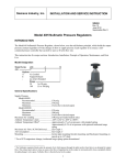
The Model 41 Nullmatic® Pressure Regulator, shown below, uses the null-balance principle, which holds the output
pressure constant regardless of wide changes in flow or supply pressure. Each regulator is in essence a selfcontained pressure controller that can deliver up to a 40 scfm flow rate.
This instruction has five major sections: Introduction, Installation, Principle of Operation, Maintenance, and Parts
List.
Model Designation
Model Series
41
A
41
Options
A
Air Loaded
N
Nonbleed
(no letter) Standard
Range
15
0.1 to 15 psi
30
0.15 to 30 psi
50
0.15 to 50 psi
100
0.2 to 100 psi
2550
24.5 to 50 psi
50
General Specifications
Supply Pressure ....................................................See Table below
Model No
41-15
41A15
41N15
41-30
41A30
41-50
41A50
41-2550
41-100
41A100
Recommended (psi)
75
75
75
120
120
120
120
120
150
150
Maximum (psi)
150
150
150
150
150
150
150
150
250
250
Minimum
5 psi above output
setting to be used
7 psi above output
setting to be used
Note: Performance
will be improved by
increasing the supply
pressure above the
minimum value.
Maximum Capacity ..............................................9 scfm with 100 psi supply and 25 psi output
Maximum Air Loading.........................................100 psi (air loaded models only)
Ambient Temperature Limits ...............................-40°C to 82°C (-40°F to 180°F)
1
SD41
INSTALLATION
Refer to Figure 1 for mounting dimensions, connections, and mounting configurations. The regulator may be
mounted in any position in a reasonable vibration-free location.
CAUTION
Exceeding the ambient air temperature limits can adversely affect performance and may
cause damage.
Pneumatic Connections
All connections are 1/8" NPT. Recommended piping to the regulator is 1/4" O.D. tubing, although any scale free
piping may be used.
1. Blow out all piping before any connections are made to prevent dirt or chips from entering the regulator.
2. Use pipe sealant sparingly, and then only on the male threads. A non-hardening sealant is strongly recommended.
3. Connect the regulator to a source of clean, dry, oil-free instrument air. See Instrument Air Requirements.
CAUTION
Supply pressure in excess of the maximum value listed in General Specifications may
cause damage. Air loading pressure in excess of 100 psi may cause damage in air loaded
models.
Figure 1 Dimensions and Mounting
Instrument Air Requirements
Connect the regulator to a source of clean, dry, oil-free instrument air. Failure to do so will increase the possibility
of a malfunction or deviation from specified performance.
CAUTION
Use of process fluids other than instrument air is not recommended. No claim is made as to
the suitability of this product for use with other process fluids, such as hazardous gases,
except as listed on the appropriate certificate. Non-approved instruments are suitable for
use with instrument air only. Optional features and modifications such as tapped exhaust do
not imply suitability for use with hazardous gases except as listed on the approval
certificate.
CAUTION
Synthetic compressor lubricants in the air stream at the regulator may cause the regulator to
fail.
2
SD41
There are many types of synthetic lubricants. Some may not be compatible with the materials used in construction of
the regulator. Wetting of these materials by such an oil mist or vapor, etc. may cause them to deteriorate. This may
ultimately result in failure of the regulator. The following materials are in contact with instrument air: Aluminum,
Brass, Buna-N, Delrin, Neoprene, Stainless Steel, and Teflon.
The requirements for a quality instrument air supply can be found in the Instrument Society of America's "Quality
Standard for Instrument Air" (ISA-S7.3). Basically this standard calls for the following:
Particle Size - The maximum particle size in the air stream at the instrument should be no larger than 3 microns.
Dew Point - The dew point, at line pressure, should be at least 10° C (18° F) below the minimum temperature to
which any part of the instrument air system is exposed at any season of the year. Under no circumstances should the
dew point, at line pressure, exceed 2° C (35.6° F).
Oil Content - The maximum total oil or hydrocarbon content, exclusive of non-condensables, should not exceed 1
ppm under normal operating conditions.
PRINCIPLE OF OPERATION
A fine-turn, precision screw is used to manually load the
"range spring" which sets the regulated pressure. When the
adjusting knob is turned clockwise, for example, the increased
spring force is exerted on the "top diaphragm assembly" which
decreases the "nozzle" clearance and increases the pilot
pressure. The source for pilot pressure is supply air flowing to
the "pilot pressure chamber" through the "restriction screw".
The increased pilot pressure forces the "exhaust diaphragm
assembly" downward, closing the "exhaust port", contacting
and moving the "valve plunger" and thereby opening the
"supply port". This increases the "regulated output" which also
feeds back to the "top diaphragm assembly." The regulator
locks-up or throttles at the new output valve when the feedback force of the "top diaphragm assembly" equals the "range
spring force."
On dead end service, regulators with no "N" in the model
number will exhaust approximately 0.1 scfm out of the holes
in the exhaust ring.
Figure 2 Schematic
MAINTENANCE
Most problems associated with pneumatic instruments can be prevented by providing clean, dry, oil-free instrument
quality air as described in Installation, Instrument Air Requirements. No routine maintenance procedures are
recommended if these requirements are observed.
Refer to the Trouble Analysis table on the next page when troubleshooting the regulator.
Lubricating the Adjusting Screw
An occasional application of light grease to the adjusting screw threads will facilitate easy turning of the adjusting
knob, especially in the high-pressure models.
Cleaning the Restriction Screw
If the small orifice in the restriction becomes blocked, press the cleaning plunger built into the body of the regulator.
The spring loading in the assembly permits it to return to its normal position.
3
SD41
Cleaning the Valve Plunger
1.
Turn off supply air.
2.
Remove the retaining nut on the bottom forging. The valve plunger and plunger spring will drop out when this
nut is removed; be careful not to lose them.
3.
Clean the valve plunger on both the ball and tapered-end surfaces. If necessary, use a non-abrasive solvent.
4.
Clean the supply seat and exhaust seat. The exhaust seat can be reached using a tobacco pipe cleaner. Here
again, use non-abrasive solvents.
5.
Install removed parts; see the parts list for part orientation. Tighten the retaining nut securely.
Disassembling the Regulator
Before disassembling, back-off the adjusting knob to relieve spring tension. Also, make a diagonal mark across all
mating parts to provide easier alignment of parts during reassembly. To disassemble the regulator, refer to the parts
list drawings for part location and remove the body screws.
Assembling the Regulator
The exhaust diaphragm assembly and exhaust ring must be positioned so that none of the holes on the pilot
base are blocked. The external holes on the exhaust ring line up under the output connection.
Position the cleaning plunger of the pilot ring assembly in line with the input connection of the pilot base.
Locate the upper diaphragm and top housing in any position; insert and tighten body screws.
Trouble Analysis
Symptom
No output
Output cannot be
increased to full value
Cause
No supply air
Clogged restriction
Supply air setting too low
Valve plunger being held open on
exhaust seat by a chip (e.g. pipe dope,
Teflon tape, thread shaving, pipe scale).
Usually detected by a heavy exhaust.
Remedy
Turn on supply air.
Press cleaning plunger.
Raise to recommended value.
Remove valve plunger and
clean the seat.
Changing the Range
The range of any Model 41 regulator may be changed by replacing the range spring, differential spring, the
upper diaphragm assembly, and other parts as noted in the parts list.
Replacing Parts
Refer to the parts list(s) at the back of this instruction when performing maintenance on a Model 41. A parts list
provides a list of replacement parts and an exploded view of the regulator.
Service kits containing spare and replacement parts are available from Siemens. See the Customer/Product Support
section to contact Siemens. Refer to the Parts List section for kits and recommended on-hand spare parts.
4
SD41
Customer/Product Support
Support is available through an online Support Request service; a link is provided in the table at the end of this
section.
When contacting Siemens for support:
•
•
Please provide complete product information:
•
For hardware, this information is provided on the product nameplate (part number or model number,
serial number, and/or version).
•
For most software, this information is given in the Help > About screen.
If there is a problem with product operation:
•
Is the problem intermittent or repeatable? What symptoms have been observed?
•
What steps, configuration changes, loop modifications, etc. were performed before the problem
occurred?
•
What status messages, error messages, or LED indications are displayed?
•
What troubleshooting steps have been performed?
•
Is the installation environment (e.g. temperature, humidity) within the product’s specified operating
parameters? For software, does the PC meet or exceed the minimum requirements (e.g. processor,
memory, operating system)?
•
A copy of the product Service Instruction, User’s Manual, or other technical publication should be at hand. The
Siemens public Internet site (see the table) has current revisions of technical literature, in Portable Document
Format, for downloading.
•
To send an instrument to Siemens for warranty or non-warranty service, call Customer Service and Return to
request a Return Material Authorization (RMA); see the table below.
IMPORTANT
An instrument must be thoroughly cleaned (decontaminated) to remove any process materials,
hazardous materials, or blood-borne pathogens prior to return for repair. Read and complete the
Siemens RMA form(s).
For support and the location of your local Siemens representative, refer to the table below for the URL of the
Process Instrumentation (PI) portion of the Siemens public Internet site. Once at the site, click Support in the right
column and then Product Support. Next select the type of support desired: sales, technical (see the table below),
documentation, or software.
5
SD41
Online Support Request
http://www.siemens.com/automation/support-request
Technical Support
1-800-333-7421; 8 a.m. to 4:45 p.m. eastern time, Monday through Friday (except
holidays)
Customer Service & Returns
1-800-365-8766 (warranty and non-warranty)
Public Internet Site
http://www.usa.siemens.com/pi
Technical Publications
in PDF
Click the above link to go to the Siemens Internet site and then click Process
Instrumentation. In the column to the right, click Support > Manuals. In the
column to the left, select the product line (e.g. Pressure or Temperature or
Controllers) to open navigation and search panes. Note: Navigation may change as
the site evolves.
Warranty
The sales contract contains the entire obligation of Siemens. The warranty contained in the
contract between the parties is the sole warranty of Siemens. Any statements continued herein do
not create new warranties or modify the existing warranty.
Teflon® is a registered trademark of E. I du Pont de Nemours and Company.
All product designations may be trademarks or product names of Siemens Industry, Inc. or other supplier companies whose use
by third parties for their own purposes could violate the rights of the owners.
Siemens Industry, Inc. assumes no liability for errors or omissions in this document or for the application and use of information
in this document. The information herein is subject to change without notice.
Procedures in this document have been reviewed for compliance with applicable approval agency requirements and are
considered sound practice. Neither Siemens Industry, Inc. nor these agencies are responsible for product uses not included in the
approval certification(s) or for repairs or modifications made by the user.
6
SD41
PARTS LIST
Siemens Nullmatic® Pressure Regulator, Model 41
Drawing 6751PL
12/81 Supersedes 1/81
IMPORTANT
Service Parts Kits are available for servicing the instrument. Contact Siemens for currently available kits; refer to
the Customer/Product Support section of this instruction. Some parts in this Parts List may not be available for
separate purchase.
7