1
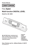
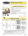
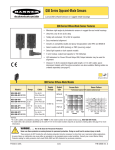
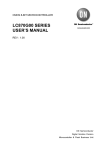
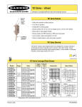
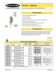
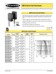
M12 Class 1 Laser Emitter
IEC Class 1 Laser for use with Banner modulated receivers
Features and Benefits
• A low-power device emitting a visible red beam (650 nm wavelength).
• Beam is bore-sighted to within 2 milliradians and 0.25 mm of the housing centerline.
• Collimated, apertured beam is 2mm diameter with divergence of less than 1 milliradian.
• Compatible with a variety of Banner modulated photoelectric receivers (see Excess Gain
chart, page 3).
• Useful for medium-range sensing, or for sensing very small objects or profiles; excellent
mechanical repeatability in position-sensing applications.
• Smooth-barrel aluminum housing is suitable for a precision mount.
• Available with unterminated, 2 m (6.5') cable or 150 mm (6") pigtail, quick-disconnect
cable
• Modulated beam (33kHz, 25% duty cycle)
CAUTION . . .
Never stare directly into
the emitter lens. Laser
light can damage your eyes.
Avoid placing any mirror-like object in
the beam. Never use a mirror as a
target. (See Figure 5.)
• 57 mm (2.25") long overall
• 10 to 30V dc operation
Models
Models
Range
Cable*
2m (6.5')
Range varies,
Unterminated
depending on
which receiver is
used (see Excess
Gain chart,
150 mm (6") Pigtail
page 3).
with 3-wire
Pico-style QD
connector
M126E1LD
M126E1LDQ
Supply
Voltage
Effective Beam at Receiver
Excess Gain
Opposed
Distance
Beam
Width
at 25ºC
10-30V dc
See chart on page 3.
1.5 m (5')
3 m (10')
6 m (20')
15 m (50')
30 m (100')
3.5 mm (0.14")
5.5 mm (0.2")
8.5 mm (0.3")
18 mm (0.7")
32 mm (1.3")
*9 m (30') cables are available by adding suffix “W/30” to the model number to the cabled version (e.g., M126E1LD W/30).
A model with a QD connector requires an accessory mating cable. See page 6.
WARNING . . . Not To Be Used for Personnel Protection
Never use these products as sensing devices for personnel protection. Doing so could lead to serious injury or death.
These sensors do NOT include the self-checking redundant circuitry necessary to allow their use in personnel safety
applications. A sensor failure or malfunction can cause either an energized or de-energized sensor output condition. Consult your current
Banner Safety Products catalog for safety products which meet OSHA, ANSI and IEC standards for personnel protection.
Printed in USA
10/03
P/N 53808 rev. B
M12 Class 1 Laser Emitter
M12 Class 1 Laser Emitter Specifications
Supply Voltage and Current
10 to 30V dc (10% maximum ripple) at less than 30 mA
Supply Protection Circuitry
Protected against electrostatic discharge (ESD) and transient voltages;
Protected against reverse polarity
Delay at Power-up
Less than 30 milliseconds
Sensing Beam
650 nm visible red laser (temperature coefficient 0.2 nm/°C);
Pulse Width: 7µs
Rep Rate: 30µs
Peak Output Power: 0.36 milliwatts
Beam Diameter at Aperture
Approximately 2 mm (0.08") diameter
Beam Divergence
±0.5 milliradians typical at 25°C; ±1.0 milliradian at operating temperature extremes
Beam Placement
Within 0.25 mm (0.01") and ±2 milliradians of mechanical centerline axis of housing
Laser Control
Apply +10 to 30V dc to black wire to enable beam; Inhibit beam by applying 0V dc or by opening circuit;
Enable delay less than 30 milliseconds; Inhibit delay less than 1 millisecond
Indicators
Indicators are visible through rear cover.
Green indicates power applied
Yellow indicates laser enabled
Construction
12.7 mm (0.50") diameter smooth aluminum barrel; Black hard-coat anodized finish, MIL-A-8625 Type III, Class II
Environmental Rating
NEMA 6; IEC IP67
Connections
PVC-jacketed 3-conductor 2 m (6.5') or 9 m ( 30') high-flex cable (unterminated); or
150 mm (6") pigtail with 3-wire Pico-style connector
Operating Temperature
Temperature: 0° to 40° C (32° to 104° F); Maximum relative humidity: 90% at 40° C (non-condensing)
Laser Classification
Class 1 laser product; complies with 21 CFR 1040.10, EN 60825-1:2001 except for deviations pursuant to
laser notice No. 50, dated 7-26-01
Certifications
2
P/N 53808 rev. B
Banner Engineering Corp. • Minneapolis, U.S.A.
Website: http://www.baneng.com • Tel: 763.544.3164
M12 Class 1 Laser Emitter
CAUTION
M12 Dimensions
Aperture/Caution Label
(Do not clamp only in this area)
See "Connections"
in Specifications
DO NOT ST
INTO BEA
Peak Power: 2.2mW, 0.36
33kHz 25% duty cycle
LASER RADIA
Green LED
Indicates power applied
Yellow LED
Indicates laser enabled
ø12.7 mm
(0.50")
57 mm
(2.25")
Excess Gain
Excess Gain of the M12 emitter is dependent on the particular receiver used.
Following is a comparison of the excess gain for various recommended receivers at
15 m (50').
Receiver
Excess Gain
at 15 m (50')
Receiver
Excess Gain
at 15 m (50')
MINI-BEAM
MULTI-BEAM
SBRX1
1,900
SM31R
250
SBR1
1,900
SM31RL
1,700
SBRXD1
1,900
SM31RMHS
180
SBRD1
1,900
SM31RLMHS
1,100
ECONO-BEAM
MAXI-BEAM
RSBR
RSBRSR
1,400
150
VALU-BEAM
SE61R
60
SE61RMHS
50
Others
SMW95R
3,400
SM51RB
120
SMI91RQD
1,800
Q23SN6R
40
EZ-BEAM
T18SN6R
750
T30SN6R
750
S12SN6R
750
Q10AN6R
25
Q45BB6R
900
For information on compatibility of the M12 emitter with other Banner photoelectric
receivers contact the factory Applications Group at the address or numbers listed on
the back cover.
Banner Engineering Corp. • Minneapolis, U.S.A.
Website: http://www.baneng.com • Tel: 763.544.3164
P/N 53808 rev. B
3
M12 Class 1 Laser Emitter
Mounting
Mounting suggestions:
• To take advantage of the bore-sight beam placement offered by
the M12 laser emitter, use a two-part clamp mount or a
mounting block with a precision-drilled hole. Allow minimum
clearance for the 12.7 mm (0.50") diameter housing, max. dia.
12.83 mm (0.505").
• Clamp on both sides of the label. Do not clamp only on the
labeled area. Use only plastic-tipped screws or set screws –
not metal – to avoid compression of the housing.
Mounting bracket assembly model SMB46X3 is recommended for
use with the M12 (see Figure 1 and ordering information on page
7). It consists of:
• A black-anodized aluminum block with holes drilled for
mounting in any of 3 directions and plastic set screws, and
•
Figure 1. Model SMB127 mounting block
An adjustable stainless steel bracket with 3 spring-loaded
screws (2 of which are used for precise alignment).
The mounting block may be ordered separately, (model SMB127;
see pages 6 and 7).
To mount the M12, insert the laser emitter into the black mounting
block, through any of the three holes. Check to be sure that the
label area of the emitter is not aligned with a set screw, then tighten
the set screws (using the supplied 3/64" Allen wrench) so the
emitter is held snugly in place. Then mount the block to the
adjustable baseplate (or to your own bracket). Mount the bracket
base using your own M5 or #10 screws or bolts, and then check
for alignment (see page 5). Tighten or loosen one or two of the
precision alignment screws (using the supplied 2 mm Allen
wrench) until the laser is accurately aligned.
Figure 1a. Mounting bracket model SMB46X3, front and rear views
Figure 2. Three possible M12 orientations
4
P/N 53808 rev. B
Banner Engineering Corp. • Minneapolis, U.S.A.
Website: http://www.baneng.com • Tel: 763.544.3164
M12 Class 1 Laser Emitter
Alignment
Approx. 2 mm
Approx.
0.5mrad = 0.029º
Laser Emitter
Sensing Distance = X
W
Conventional modulated infrared LED photoelectric emitters are
designed with beam divergence angles of several degrees. As a
result, most emitters are easily aligned to their receivers by
simple line-of-sight methods.
W = 2 mm + 2X(tan.0029º) = 2 mm + X(0.001)
Opposed Distance (X)
In sharp contrast to conventional photoelectric emitters,
M12 laser emitters have a beam divergence of only 0.03°
(0.5 milliradians) at 25° C (77°F) ambient temperature (see
Figure 3). This translates, for example, to a beam diameter of
only 0.3" at a distance of 20'. Consequently, there is very little
forgiveness for angular misalignment.
Beam Width (W)
1.5 m (5')
3.5 mm (0.14")
3 m (10')
5.0 mm (0.2")
6 m (20')
8.0 mm (0.3")
15 m (50')
17 mm (0.7")
30 m (100')
32 mm (1.3")
The beam size listed in Figure 3 is also the effective beam size
at the receiver. The effective beam is equal to the minimum
opaque object profile required to block the light beam. The
beam size at the emitter is 2 mm (.08") diameter.
Figure 3. M12 laser emitter beam divergence at 25ºC
(beam size vs. distance)
Ø = Misalignment Angle
Y
Sensing Distance = X
Laser Emitter
Y = X(tan Ø)
Opposed Distance (X)
Beam Displacement (Y)
for 1º of Misalignment
1.5 m (5')
25 mm (1")
3 m (10')
50 mm (2")
6 m (20')
100 mm (4")
15 m (50')
250 mm (10")
30 m (100')
500 mm (20")
Figure 4. Beam displacement per degree of misalignment
;;
@@
;;
@@
;;
@@
Target
M12
Receiver
The effect of angular misalignment is dramatic (see Figure 4).
The wide beam angles offered by conventional photoelectric
emitters allow several degrees of misalignment between the
optical axes of the emitter and receiver. This is not true for
laser emitters which require their beam center to directly strike
the receiver lens. Figure 4 shows how far the laser beam will
miss the center of the receiver lens for each degree of angular
misalignment (in any plane). Note that even at only a 5' range,
one degree of misalignment will cause the laser beam to miss
the lens of most receivers.
Alignment Tip: The visible red beam of the laser emitter is
easily seen in subdued lighting. At opposed distances of up to
10', attach a sheet of white paper directly in front of the
receiver lens. Mark the location of the lens center on the paper.
This mark is used as an aiming target. Sight along the beam
from directly behind the laser emitter. Adjust the emitter
mounting until the red image (the dot of red light) is centered
exactly on the mark. Remove the paper and check the response
of the receiver.
For longer distances (up to 25'), replace the white paper with a
4" x 4" square of high-grade retroreflective tape (Banner model
BRT-THG-4X4-5 or equivalent; see Figure 5). For greater
distances, use a larger sheet of retroreflective material (see
page 7).
Figure 5. At long distances, use retroreflective tape to locate the
beam at the receiver location. Never use a mirror as an
alignment target.
Banner Engineering Corp. • Minneapolis, U.S.A.
Website: http://www.baneng.com • Tel: 763.544.3164
P/N 53808 rev. B
5
M12 Class 1 Laser Emitter
Hookups
M126E1LD Laser Diode Emitter
Unterminated Cable
bk
bn
bu
M126E1LDQ Laser Diode Emitter
3-pin Pico-style Connector
Laser beam
enable
bk
+
10-30V dc
bn
Laser beam
enable
+
10-30V dc
bu
-
-
Mounting Bracket Dimensions
SMB46X3 Bracket Assembly
SMB127 Mounting Block
2x 11.4 mm
(0.45")
2x 7.1 mm
(0.28")
36 mm
(1.4")
12.9 mm
(0.508")
10.6 mm
(0.42")
21.1 mm
(0.83")
23.6 mm
(0.93")
31.8 mm
(1.25")
14.0 mm
(0.55")
60º
3x #4-40 Thru
21.6 mm
(0.85")
10.6 mm
(0.42 ")
2x M3
or #4 Clearance
12.9 mm
(0.508")
12.9 mm
(0.508")
8x M5 or #10 clearance
ø6.6mm
(0.26")
ø30.5mm
(1.20")
60º
26.9 mm
(1.06")
22.9 mm
(0.90")
36 mm
(1.4")
17.8 mm
(0.70")
13.5 mm
(0.53")
6.4 mm
(0.25")
5.1 mm
(0.20")
18.5 mm
(0.73")
21.6 mm
(0.85")
17.8 mm
(0.70")
64.5 mm
(2.54")
61 mm to 64 mm
(2.4" to 2.5")
6
P/N 53808 rev. B
61.0 mm
(2.40")
Banner Engineering Corp. • Minneapolis, U.S.A.
Website: http://www.baneng.com • Tel: 763.544.3164
M12 Class 1 Laser Emitter
Accessories
Mounting Brackets
Model
Description
SMB46X3
Assembly with mounting block and adjustable bracket
Comes with: 2mm Shortarm hex key
3/64" Shortarm hex key
4 Set screws
SMB127
Mounting block only
Comes with: 3/64" Shortarm hex key
4 Set screws
Retroreflective Tape
Model
BRT-THG-4X4-5
BRT-THG-8.5X11-2
BRT-THG-18X36
Reflectivity
Maximum
Factor
Temperature
0.7
0.7
0.7
60°C (140°F)
60°C (140°F)
60°C (140°F)
Size
Unit
100 x 100 mm (4" x 4")
216 x 280 mm (8.5" x 11")
457 x 914 mm (18" x 36")
Package of 5
Package of 2
Single Sheet
Pico-Style Quick-Disconnect Cables
Cable: PUR jacket, polyurethane connector body, POM snap-lock coupling
Conductors: 26 or 24 AWG high-flex stranded, gold-plated contacts
Temperature: -40º to +90°C (-40º to +194°F)
Voltage Rating: 30V ac/36V dc
Environmental Rating: None
Model
Style
Length
Dimensions
Pin-out
ø10 mm max.
(0.4")
PKG3-2
3-Pin
Straight
Black Wire
2 m (6.5')
Blue Wire
Brown Wire
28 mm max.
(1.1")
Banner Engineering Corp. • Minneapolis, U.S.A.
Website: http://www.baneng.com • Tel: 763.544.3164
P/N 53808 rev. B
7
M12 Class 1 Laser Emitter
WARRANTY: Banner Engineering Corp. warrants its products to be free from defects for one year. Banner Engineering Corp. will repair or
replace, free of charge, any product of its manufacture found to be defective at the time it is returned to the factory during the warranty
period. This warranty does not cover damage or liability for the improper application of Banner products. This warranty is in lieu of any
other warranty either expressed or implied.
P/N 53808 rev. B
Banner Engineering Corp., 9714 Tenth Ave. No., Minneapolis, MN 55441 • Phone: 763.544.3164 • www.bannerengineering.com • E-mail: [email protected]