1
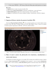
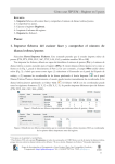
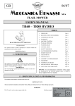
Department of Cartographic Engineering, Geodesy and Photogrammetry 3DVEM – Register User Manual March 2014 3DVEM – Register Index 1. Presentation......................................................................................................... 2 2. Installing the software................................................................................... 3 3. Introduction to the registration process ...................................................... 4 4. Main Interface ............................................................................................... 7 4.1. Menu .............................................................................................................. 7 4.1.1. Project menu.............................................................................................. 9 4.1.2. Data menu................................................................................................ 10 4.1.3. Tools Menu............................................................................................... 11 4.2. Workspace Panel ......................................................................................... 12 4.3. Targets/Spheres/Points Panel .................................................................... 13 4.4. Preferences Panel ........................................................................................ 15 4.4.1. Adjustment............................................................................................... 15 4.4.2. Leveled ..................................................................................................... 16 4.4.3. Units ......................................................................................................... 16 4.4.4. Matching .................................................................................................. 17 4.5. Adjustment Summary Panel ....................................................................... 17 4.6. External Orientation Parameters Panel...................................................... 18 4.7. Targets/Spheres/Points Coordinates and Residuals Panel........................ 19 5. Adjustment possibilities.............................................................................. 20 Photogrammetry & Laser Scanning Research Group (GIFLE). Department of Cartographic Engineering, Geodesy and Photogrammetry. Universitat Politècnica de València. Cº de Vera s/n. Building 7i. gifle.webs.upv.es. Tel. (+34)963877007 Ext. 75532. [email protected] 1 3DVEM – Register 1. Presentation 3DVEM – Register has been implemented by GIFLE (Photogrammetry & Laser Scanning Research Group) at the Department of Cartographic Engineering, Geodesy and Photogrammetry, Universitat Politècnica de València, Valencia (Spain). 3DVEM – Register is a powerful low‐cost software that solves the registration, also known as alignment or relative orientation, of point clouds, point clouds and 3D models, as well as 3D models, all of them registered, from a sufficient number of matching (homologous) features identified in a variety of ASCII formats. Matching features may be centres of targets and spheres, among others, as well as natural points or points extracted from digital models. Matching features is automatic in principle, since the software sets internally features, and solves the indirect registration by means of either least squares or robust estimation, depending on the option selected by the user. Photogrammetry & Laser Scanning Research Group (GIFLE). Department of Cartographic Engineering, Geodesy and Photogrammetry. Universitat Politècnica de València. Cº de Vera s/n. Building 7i. gifle.webs.upv.es. Tel. (+34)963877007 Ext. 75532. [email protected] 2 3DVEM – Register 2. Installing the software 3DVEM – Register works on Windows operating system. Double‐click the file "Setup.exe" to install the software. Fig. 1 shows the steps needed to install the software. Once installed you can run the software double clicking the 3DVEM ‐ Register icon located on the desktop. The license will have to be installed either in local or in network mode. Contact gifle.webs.upv.es to get a USB key; otherwise the DEMO version will run. (a) (b) (c) (d) (e) (f) Fig. 1. Installing 3DVEM – Register Photogrammetry & Laser Scanning Research Group (GIFLE). Department of Cartographic Engineering, Geodesy and Photogrammetry. Universitat Politècnica de València. Cº de Vera s/n. Building 7i. gifle.webs.upv.es. Tel. (+34)963877007 Ext. 75532. [email protected] 3 3DVEM – Register 3. Introduction to the registration process Most of laser scanning projects require several scans from different positions to complete the overall 3D digitization as well as avoiding possible occlusions. Each scan will be referred to its own laser scanner system, whose coordinate origin is the instrument’s origin of measurements (Fig. 2a). Therefore, a correct visualization of the full point cloud integrated by all the partial scans will require some orientation processing, alignment (Fig. 2b). This three‐dimensional spatial orientation process whereby different scan coordinate systems are referenced to a common coordinate system is usually known as registration or alignment, and corresponds to a 3D rigid body transformation. The 3D rigid body transformation integrates 6 external (also known as exterior) orientation parameters, 3 rotations and 3 translations, each one on a coordinate axis. This common coordinate system where all the points are finally referred to is usually known as main reference system in the field of topography1. Registration techniques are often divided in direct and indirect, depending on the mode it is undertaken. It is called direct registration (or georeferencing) when the instrument’s position and orientation is known, and allows users to obtain measurements and point clouds directly referenced. The way of knowing its position and orientation depends on the available instrument and its characteristics. The equipment might be placed on a point of known coordinates by a laser plummet and be oriented to another known point, or make use of GNSS (GPS, GLONASS, Galileo…) and INS. 1 It is called Home Scanworld by the Leica Cyclone‐REGISTER software. The main reference system is usually highlighted in the user interface. Photogrammetry & Laser Scanning Research Group (GIFLE). Department of Cartographic Engineering, Geodesy and Photogrammetry. Universitat Politècnica de València. Cº de Vera s/n. Building 7i. gifle.webs.upv.es. Tel. (+34)963877007 Ext. 75532. [email protected] 4 3DVEM – Register (a) (b) Fig. 2. Top view of several coloured point clouds by station: a) raw (unregistered); b) registered Indirect registration techniques will require the arrangement and identification of matching features in different local LiDAR coordinate systems. Since relationship between two laser scanning systems will be given by a set of 6 orientation parameters, a minimum of three homologous features will be required for a least squares resolution (although four are recommended) or two in case of levelled instruments, a Photogrammetry & Laser Scanning Research Group (GIFLE). Department of Cartographic Engineering, Geodesy and Photogrammetry. Universitat Politècnica de València. Cº de Vera s/n. Building 7i. gifle.webs.upv.es. Tel. (+34)963877007 Ext. 75532. [email protected] 5 3DVEM – Register fact that would constraint the rotations around X (Omega) and Y (Phi) axes. In any case, it is recommended to have more corresponding features to detect any errors in the spatial transformation. Distinction in indirect registration techniques will be given by the provenance of these homologous features. Normally and when accessibility allows it, indirect registration will be performed using targets, spheres or artificial patterns recognized by the instrument that yield high precision in measurements; some software call this process target to target registration simply because targets are matched, or point to point registration when natural points are identified in the point clouds. In any case, targets, spheres or points are used to materialize the information that supports the 3D transformation. The best results will be achieved firstly with spheres, secondly with paddle targets, and thirdly with printed artificial patterns ideally distributed in 3D space, whenever their geometries are recognised and extracted by specific software. The most common approach is to use registration targets provided by manufacturer and scan them with the laser scanner, which will determine automatically their centroids and add their coordinates into the working file. Other indirect registration possibilities such as cloud to cloud registration, surface to surface registration and point to surface registration can be implemented in 3DVEM – Register whereas the user measures interactively the points and include them in the corresponding files, or typing, for instance, in the free software 3DVEM – Viewer, Editor & Meter. The functionalities and controls available in the 3DVEM – Register software will be presented next. Photogrammetry & Laser Scanning Research Group (GIFLE). Department of Cartographic Engineering, Geodesy and Photogrammetry. Universitat Politècnica de València. Cº de Vera s/n. Building 7i. gifle.webs.upv.es. Tel. (+34)963877007 Ext. 75532. [email protected] 6 3DVEM – Register 4. Main Interface 3DVEM – Register presents a single interface divided in seven different areas (Fig. 3): 1. 2. 3. 4. 5. 6. 7. Menu. Workspace Panel. Targets/Spheres/Points Panel. Preferences Panel. Summary of the Adjustment Panel. External Orientation Parameters Panel. Targets/Spheres/Points Coordinates and Residual Panel. Fig. 3. Main window of 3DVEM – Register 4.1. Menu The toolbar on top of the main window (Fig. 3) is organized in four pull‐down menus: Project: includes the commands to manage projects, save and generate reports and 3D visualisations (Fig. 4). Photogrammetry & Laser Scanning Research Group (GIFLE). Department of Cartographic Engineering, Geodesy and Photogrammetry. Universitat Politècnica de València. Cº de Vera s/n. Building 7i. gifle.webs.upv.es. Tel. (+34)963877007 Ext. 75532. [email protected] 7 3DVEM – Register Data: contains the import / export data commands (Fig. 5). Tools: contains the registration, reset the adjustment and change language commands (Fig. 6). Help: shows the content of this document and provides details about the version and software copyright (Fig. 7). The pull‐down menus available in the toolbar are displayed next (Figs. 4‐7). Fig. 4. Project menu Fig. 5. Data menu Fig. 6. Tools menu Fig. 7. Help menu Photogrammetry & Laser Scanning Research Group (GIFLE). Department of Cartographic Engineering, Geodesy and Photogrammetry. Universitat Politècnica de València. Cº de Vera s/n. Building 7i. gifle.webs.upv.es. Tel. (+34)963877007 Ext. 75532. [email protected] 8 3DVEM – Register 4.1.1. Project menu The software works with files written in XML language that allows saving the main project features. The Project menu (Fig. 4) allows users to create a new project, open an existing project and save the actual project. The Project menu includes more commands: 1. Save adjustment reports. The software offers the possibility to generate a text file which will include a report with the adjustment results. Furthermore, it will contain all the information regarding loaded and adjusted data such as used files, matching table, number of iterations, root mean square error, exterior orientation parameters per scanner position and related uncertainty, used targets in the adjustment and associated residuals. 2. Generate 3D. Save optionally in VRML/DXF format, all the adjustment data to visualise interactively them in 3D. Data such as control points, the position and orientation of the LiDAR system, and the digitised points (with the chance to reduce the sample by percentage (%)) can be saved. Fig. 8 shows the window that allows users to generate 3D files by means of Generate 3D. Fig. 8. Options to generate VRML and DXF files 3. Exit application. Photogrammetry & Laser Scanning Research Group (GIFLE). Department of Cartographic Engineering, Geodesy and Photogrammetry. Universitat Politècnica de València. Cº de Vera s/n. Building 7i. gifle.webs.upv.es. Tel. (+34)963877007 Ext. 75532. [email protected] 9 3DVEM – Register 4.1.2. Data menu 3DVEM – Register manages different file formats usually used by surveying, photogrammetric, and terrestrial and aerial LiDAR systems, and 3D modelling software. The Data menu (Fig. 5) allows: 1. Import Files. Accepted formats for loading 3D data will be PTS and PTX (Leica Geosystems), FWS and FLS (FARO)2, LAS (ASPRS), LAZ, ASC, TXT and OBJ. Worth mentioning is that the files should contain 3D data belonging to a single reference system. In the case of point clouds acquired by a terrestrial laser scanning each file will contain scans from a single station. PTS format files can handle point clouds as well as coordinates of the centroids of the targets/spheres/points measured from each station3. Following this way, a single file will load both the point clouds and the points for registration. Furthermore, the FLS format allows users to include spheres measured in FARO SCENE. When using other formats, the coordinates of the points for registration will be stored in separate files and loaded afterwards in the program. Alternatively, the point coordinates can also be written on the Targets/Spheres/Points Panel. 2. Export Files. 3D data export whether they are transformed or not may be undertaken in the following formats: PTS, PTX, LAS, LAZ, ASC, TXT, VRML and OBJ. Files can be exported following different ways: Single. It will generate an output file for each input file. All in one. It will generate a single output file which will contain all the items contained in the partial scans transformed to the main reference system selected by the user. To folders .fls. The user has to specify the folder where all the raw .fls subfolders downloaded from the system containing both the FLS file and the Main file that stores the attributes of the scan. Fig. 9 shows the steps to save the transformation parameters obtained from 3DVEM – Register for each scan. This option will only be displayed active on the Data menu if the project data are imported in FLS format. 2 Avoid activating automatic feature matching in FARO SCENE to work in a local laser scanner reference system. 3 In case of choosing both point clouds and targets while exporting data with Leica Cyclone. Photogrammetry & Laser Scanning Research Group (GIFLE). Department of Cartographic Engineering, Geodesy and Photogrammetry. Universitat Politècnica de València. Cº de Vera s/n. Building 7i. gifle.webs.upv.es. Tel. (+34)963877007 Ext. 75532. [email protected] 10 3DVEM – Register Fig. 9. Exporting FARO files 4.1.3. Tools Menu The Tools Menu (Fig. 6) contains key commands to operate 3DVEM – Register such as register, reset adjustment, delete scan or compute matches and additional tools such as language selection. More information is presented next: 1. Register. Starts the registration adjustment. 2. Reset Adjustment. Allows the user to clean the registration results while keeping the properties of targets such as name and status (active/inactive). 3. Remove Scan. Allows the user to remove the file selected in the Workspace Panel. 4. Recovery Original ID. Retrieves the number originally assigned to the targets/spheres/points. This option will only be available when working in manual mode. 5. Language. Change the language of the application (Fig. 10). Photogrammetry & Laser Scanning Research Group (GIFLE). Department of Cartographic Engineering, Geodesy and Photogrammetry. Universitat Politècnica de València. Cº de Vera s/n. Building 7i. gifle.webs.upv.es. Tel. (+34)963877007 Ext. 75532. [email protected] 11 3DVEM – Register Fig. 10. Language selection 4.2. Workspace Panel The Workspace Panel will include files with either the scanned point clouds or the 3D models that will be oriented as well as additional information (Figs. 3 and 11). Fig. 11. Workspace Panel The files are added to 3DVEM – Register after selecting Data/Import Files (Fig. 5). The table will display the names of the loaded files, as well as the number of targets, spheres or points included in each of them. Similarly, each time a file is included the matches will be automatically calculated among the rest of the scans. Matches will be reflected in the table. Three actions can be carried out from the context menu for each imported scan: delete the selected scan from the Workspace, export or generate a file with 3D data (WRML or DXF format). The context menu is displayed by clicking the right button on the existing scans. Photogrammetry & Laser Scanning Research Group (GIFLE). Department of Cartographic Engineering, Geodesy and Photogrammetry. Universitat Politècnica de València. Cº de Vera s/n. Building 7i. gifle.webs.upv.es. Tel. (+34)963877007 Ext. 75532. [email protected] 12 3DVEM – Register 4.3. Targets/Spheres/Points Panel Targets/Spheres/Points Panel will be enabled when the user selects one of the files on the Workspace Panel (Figs. 3 and 12). Fig. 12. Targets/Spheres/Points Panel The table displays the coordinates of the artificial points (targets or spheres), and/or natural points extracted from the point clouds or digital model that will define the laser scanner coordinate system of the file selected in the workspace. The list includes the numeric identifier (ID) assigned to the point. If the identifier was not included, it might be sequentially assigned or automatically matched, followed by the coordinates of the points. The PTS format allows users to include in the list targets/spheres/points features, plus the scanned points. Also, the FLS format allows users to include spheres measured in FARO SCENE. Natural points can be extracted from the digital model using the free software 3DVEM – Viewer, Editor & Meter (Fig. 2). The software is license‐free but registration is required in advance before downloading4. 3DVEM – Viewer, Editor & Meter contains tools that allow the efficient management of point clouds and three‐dimensional (3D) models as well as the simple insertion and extraction of point coordinates. It is possible to modify the contents of the tables using the following groups of tools: 1. Edition of the table. The Edit Table button activates the chance to modify both the point ID and the coordinates. This command is useful when 4 3DVEM – Viewer, Editor & Meter. http://gifle.webs.upv.es/Index.php Photogrammetry & Laser Scanning Research Group (GIFLE). Department of Cartographic Engineering, Geodesy and Photogrammetry. Universitat Politècnica de València. Cº de Vera s/n. Building 7i. gifle.webs.upv.es. Tel. (+34)963877007 Ext. 75532. [email protected] 13 3DVEM – Register the user knows the identifiers of the listed points. Also new points can be manually inserted by clicking on the Insert Point button . To validate the changes will be necessary to click on the Edit Table button . There will be allowed neither numeric identifiers nor coordinates. If either the names or the coordinates are edited, the software will automatically switch to manual mode; Manual Matching will be active on the Preferences Panel (Fig. 3). The user will be able to change later to automatic mode (Automatic Matching), but the made changes on the point names will be lost. 2. Import/Export points. Import Points button allows users to insert new points from a file. Points may be imported following the file formats: PTS, TXT, ASC, CSV, XLS and DXF. The PTS files do not allow the association of a numeric point identifier (ID). The rest of the files can have the following formats: a. X Y Z. b. ID X Y Z. For a format (file without identifiers) and depending on the type of selected matching on the Preferences Panel while importing, the 3DVEM – Register software will assign an ID to each point either in a sequential way (Manual Matching) or in an automatic way (Automatic Matching). In any case, it is recommended to make always use of the Automatic Matching, unless it does not work. For b format, the ID entered for a point has to be an integer. DXF file (version 2000 onwards) will contain the feature points ('POINT' label). In addition, each point can be associated with a text (ID). Export Points button allows users to export the selected point files in the Workspace Panel. Points may be exported in the following formats: PTS, TXT, ASC, CSV and XLS. allows users to delete the 3. Delete points. The Delete Points button selected points. The points can be retrieved by clicking on the Undo Delete button . As changes continue, 3DVEM – Register will update automatically the existing matches on the Workspace Panel. Photogrammetry & Laser Scanning Research Group (GIFLE). Department of Cartographic Engineering, Geodesy and Photogrammetry. Universitat Politècnica de València. Cº de Vera s/n. Building 7i. gifle.webs.upv.es. Tel. (+34)963877007 Ext. 75532. [email protected] 14 3DVEM – Register 4.4. Preferences Panel The 3DVEM – Register user will select on the Preferences Panel the options for the adjustment (Figs. 3 and 13). The panel is divided in four sections: 1. Adjustment. This section determines the method used for the adjustment, the increments and the maximum number of iterations. 2. Leveled. This section specifies the levelled scans on‐site and the instrumental precision. 3. Units. The input and output units will be specified. 4. Matching. This section determines whether the matching is carried out automatically by inserting a tolerance value or manually. Fig. 13. Preferences Panel 4.4.1. Adjustment In case the Robust Estimation box is activated, the registration adjustment will be solved either by the Danish Modified (Danish Mod.) method or by the Minimum Sum (Min. Sum) estimator (Fig. 13). This box is disabled by default. Therefore, the Photogrammetry & Laser Scanning Research Group (GIFLE). Department of Cartographic Engineering, Geodesy and Photogrammetry. Universitat Politècnica de València. Cº de Vera s/n. Building 7i. gifle.webs.upv.es. Tel. (+34)963877007 Ext. 75532. [email protected] 15 3DVEM – Register adjustment will be solved by classical least squares method. This is the recommended method. Minimum linear correction/Minimum angle correction (”): the registration adjustment follows an iterative and convergent approach. The user will fix a criterion to stop iterations. The process will be interrupted when the obtained corrections for the external orientation parameters are below the thresholds specified by the user (Minimum linear correction for translation parameters / Minimum angle correction for rotation parameters). By default, the set thresholds are 0.001 (m) for translations and 3” for rotations. Maximum iterations: if the previous corrections are not reached while solving the adjustment, a second stop criterion will be set. The adjustment will stop after reaching the specified maximum number of iterations independently of the magnitude of the corrections. A maximum number of 7 iterations is set by default. 4.4.2. Leveled If some of the scan stations are levelled5, the user will be able to constrain the tilt of the rotations Omega (rotation over the X‐axis) and Phi (rotation over the Y‐axis) to the accuracy specified by the manufacturer. Following this way, the adjusted values for these rotations will be restricted to the specified values. By default, the imported scans are considered unlevelled. Dual‐axis compensator (”): instrument data used for the data acquisition. The value will be introduced in seconds (decimal degrees). Null or negative values will not be allowed. An accuracy value of 1” is set by default. 4.4.3. Units Input: it will determine the order of magnitude of the input measurements, and subsequently, the output magnitudes: kilometres (km), meters (m) or millimetres (mm). 5 An instrument is considered to be leveled when its normal to the vertical axis is horizontal. Most of the times, the user needs to check that the dual‐axis compensator is on; alternatively, the user needs to level carefully the instrument before acquiring data. Photogrammetry & Laser Scanning Research Group (GIFLE). Department of Cartographic Engineering, Geodesy and Photogrammetry. Universitat Politècnica de València. Cº de Vera s/n. Building 7i. gifle.webs.upv.es. Tel. (+34)963877007 Ext. 75532. [email protected] 16 3DVEM – Register Output: it will determine the units used to print the rotations: Grades (Grd), Degrees (Deg) or Radians (Rad). 4.4.4. Matching The matching is automatically updated each time the workspace suffers any change in its content owing to adding a file, deleting a file, activating/deactivating points, editing the names of the points, insertion/deletion of points or modification of the tolerance. Matching common features will be automatically carried out by an internal algorithm that recognises points (Automatic Matching) or from numerical identifiers assigned to loaded targets/spheres/points (Manual Matching). If Manual Matching box is activated, it is understood that the point identifiers are properly assigned. So if the user does not identify or allocate convenient names to each point on the panel Targets/Spheres/Points the final adjustment would yield an erroneous result. Similarly, the Automatic Matching option will be taken into account not only when loading and editing the components of the workspace, but also when solving the adjustment and creating the so‐called virtual reference network (see Section 5. Adjustment possibilities). Automatic Matching of targets/spheres/points in different coordinate systems will require a minimum number of three matches to be successfully performed6. In case of two matches, the identification will not be automatically solved, being necessary to activate Manual Match option, identify manually homologous points and change the names of the points on the Targets/Spheres/Points Panel. Point tolerance (m): the automatic search and validation of homologous features among different scans is set based on a tolerance threshold or uncertainty while positioning targets. By default, this threshold is set to 0.01 (m). 4.5. Adjustment Summary Panel The user will be able to run the Register command in the Summary of the Adjustment Panel as well as check the overall result of the adjustment (Figs. 3 and 14). 6 It is understood that there are no gross errors in measurements. Otherwise, more observables will be required. Photogrammetry & Laser Scanning Research Group (GIFLE). Department of Cartographic Engineering, Geodesy and Photogrammetry. Universitat Politècnica de València. Cº de Vera s/n. Building 7i. gifle.webs.upv.es. Tel. (+34)963877007 Ext. 75532. [email protected] 17 3DVEM – Register Fig. 14. Summary of the Adjustment Panel The Register button allows users to solve the indirect registration or alignment. The software will calculate all possible solutions and will select as the best the one that yields higher percentage of success for the orientations (higher number of scans successfully oriented) and lower root mean square (R.M.S.) error. Number of Iterations: the registration adjustment follows an iterative approach that will be mostly solved more than once. Root Mean Square (R.M.S.) error: reports an overall quality estimate, providing the user an idea of the average error. Oriented scans: indicates the number of registered scans over the total. 4.6. External Orientation Parameters Panel The External Orientation Parameters Panel (Figs. 3 and 15) shows the results of the least squares/robust adjustment achieved for the scans included in the Workspace Panel. The rotation units will correspond to those selected by the user on the Preferences Panel. The translations will be fixed by the units from the input files. Fig. 15. External Orientation Parameters Panel Photogrammetry & Laser Scanning Research Group (GIFLE). Department of Cartographic Engineering, Geodesy and Photogrammetry. Universitat Politècnica de València. Cº de Vera s/n. Building 7i. gifle.webs.upv.es. Tel. (+34)963877007 Ext. 75532. [email protected] 18 3DVEM – Register 3DVEM – Register sets as main reference system the most suitable scan. It is marked as active (tic on) in the listed solution, and fixes the origin of rotations and translations. Selecting another scan from the list of solutions will cause a recalculation of all the transformation parameters to the new selected reference system. If any scan can not be adjusted, the fields will be marked with dashes. When the Leveled box is on, the adjustment solution is constrained and the rotation angles Omega and Phi will not participate in the adjustment. 4.7. Targets/Spheres/Points Coordinates and Residuals Panel The Targets/Spheres/Points Coordinates and Residuals Panel (Figs. 3 and 16) shows for each one of the points loaded per scan its identifiers (distinguishing between the assigned automatically by the software and the introduced by the user file), the name of the scan it belongs to, its transformed coordinates to the main reference system (the one selected in the External Orientation Parameters Panel), the residuals of the transformation, the final error generated at the point and their coordinates in the original (input) coordinate system. The control allows user to sort values after clicking on the corresponding columns. Fig. 16. Targets/Spheres/Points Coordinates and Residuals Panel Photogrammetry & Laser Scanning Research Group (GIFLE). Department of Cartographic Engineering, Geodesy and Photogrammetry. Universitat Politècnica de València. Cº de Vera s/n. Building 7i. gifle.webs.upv.es. Tel. (+34)963877007 Ext. 75532. [email protected] 19 3DVEM – Register 5. Adjustment possibilities Automatic Matching allows users to recognise automatically features. Therefore, there is neither need to follow any order on site when measuring targets/spheres nor numbering them due to the automatic matching performance. For Manual Matching, special care has to be taken with numeric identifier assigned to features before running Register. It is recommended to measure at least three features from each station. With slow LiDAR systems this process might be time consuming due to the need to measure each feature specifically on site, slowing down the data acquisition. High end LiDAR systems provide dense and quick scans, and the measurement process for multiple features can be carried out in the office, either automatically or semi‐automatically as far as the features are measured with enough resolution. Automatic search of homologous features from different station coordinate systems can be carried out as long as at least three common features exist within the established tolerance threshold. On the contrary, matching will not be automatically solved by the software. Fig. 17 shows some typical laser scanning surveys where the idea of placing spheres/targets on site or measuring points is simple. Worth noticing is the need of covering if possible the surroundings of the object to be digitised. Therefore, the idea is to plan well, materialise and measure the 3D features on the working space. Photogrammetry & Laser Scanning Research Group (GIFLE). Department of Cartographic Engineering, Geodesy and Photogrammetry. Universitat Politècnica de València. Cº de Vera s/n. Building 7i. gifle.webs.upv.es. Tel. (+34)963877007 Ext. 75532. [email protected] 20 3DVEM – Register (a) (b) (c) (d) Station Target/Sphere/Point observed Fig. 17. Different cases of automatic resolution of indirect registration of a structure, building or object: a) 4 stations and 4 observables per station, ideal case; b) 4 stations and 3 observables per station; c) 3 stations with obstruction in the central part and 3 or more observables; d) 3 stations and 3 observables per station In some cases, the presence of some error during the data acquisition on site can be solved by adapting the tolerance point threshold to its true precision, or introducing additional natural points measured in the point cloud or 3D model while processing. Another rigorous alternative to remove the influence of gross errors whenever enough number of redundancies exists is to apply robust estimators. 3DVEM – Register offers two possibilities, the Danish Modified (Danish Mod.) method and the Minimum Sum (Min. Sum) estimator (Fig. 13). In practice it might happen that there is not enough number of features between stations. The resolution of the registration, alignment or orientation in 3DVEM – Register will be performed by means of a virtual reference network which contains not only the points of the main reference system, but also those included in the rest of scans oriented from the main reference system. This fact allows users to solve the Photogrammetry & Laser Scanning Research Group (GIFLE). Department of Cartographic Engineering, Geodesy and Photogrammetry. Universitat Politècnica de València. Cº de Vera s/n. Building 7i. gifle.webs.upv.es. Tel. (+34)963877007 Ext. 75532. [email protected] 21 3DVEM – Register orientation or registration of special design/geometry cases (see Fig. 18), very common in real life practice with laser scanning which otherwise might not be automatically registered. (a) (b) (c) Station Target/Sphere/Point observed Fig. 18. Special cases which can be automatically solved by 3DVEM – Register Fig. 18 presents some of the indirect registration possibilities that can be solved by 3DVEM – Register such as target to target registration, point to point registration and point to model registration. The virtual reference network used for the resolution of the registration adjustment will allow users to solve immediately special cases, either typical cases with lack of visibility between stations (Fig. 18a), transverses for linear geometric projects (Fig. 18b), or cases where a station is oriented making use of targets observed in multiple untie stations (Fig. 18c). Photogrammetry & Laser Scanning Research Group (GIFLE). Department of Cartographic Engineering, Geodesy and Photogrammetry. Universitat Politècnica de València. Cº de Vera s/n. Building 7i. gifle.webs.upv.es. Tel. (+34)963877007 Ext. 75532. [email protected] 22