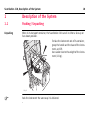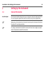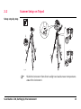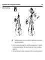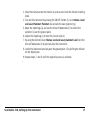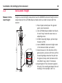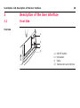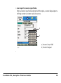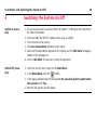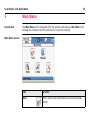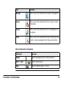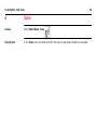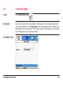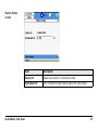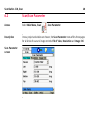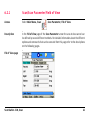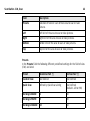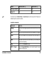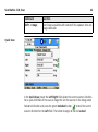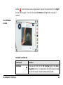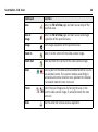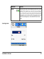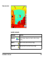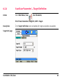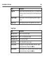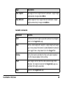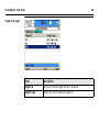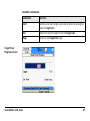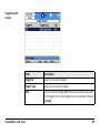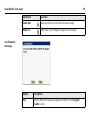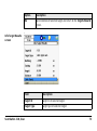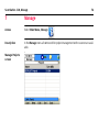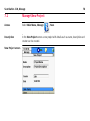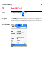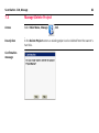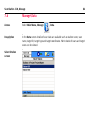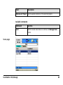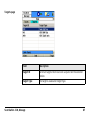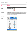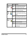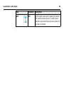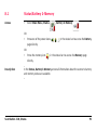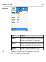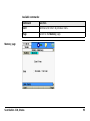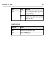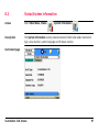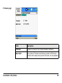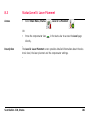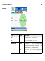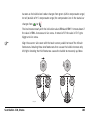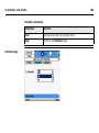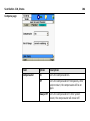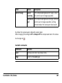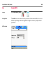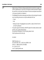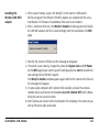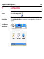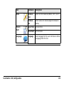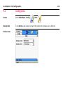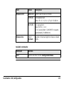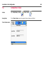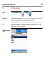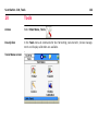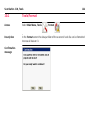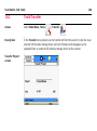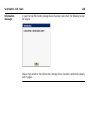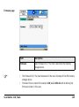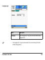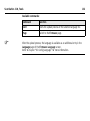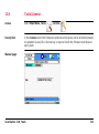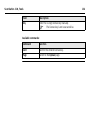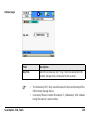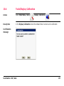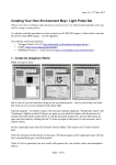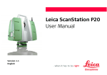
1
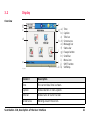
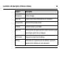
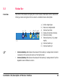
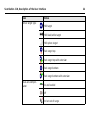
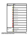
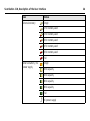
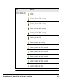
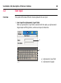
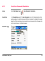
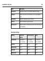
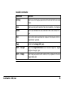
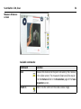
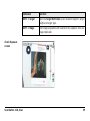
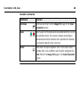
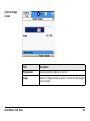
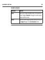
Leica ScanStation C10 System Field Manual Version 1.0 English 2 ScanStation C10, Introduction Introduction To use the product in a permitted manner, please refer to the detailed safety directions in the User Manual. Purchase Congratulations on the purchase of a ScanStation C10 instrument. Product identification The type and the serial number of your product are indicated on the type plate. Enter the model and serial number in your manual and always refer to this information when you need to contact your agency or Leica Geosystems authorised service workshop. Type: _______________ Serial No.: _______________ Symbols The symbols used in this manual have the following meanings: Type Trademarks Available documentation Description Important paragraphs which must be adhered to in practice as they enable the product to be used in a technically correct and efficient manner. • Windows is a registered trademark of Microsoft Corporation All other trademarks are the property of their respective owners. Name Description/Format Leica ScanStation C10 User Manual All instructions required in order to operate the product to a basic level are contained in the User Manual. Provides an overview of the product together with technical data and safety directions. ScanStation C10, Introduction 3 4 ScanStation C10, Introduction Name Description/Format Leica ScanStation C10 Describes the general operation of the product System Field Manual in standard use. Intended as a quick reference field guide. Leica Geosystems HDS Training Manual Training manual provided in the Leica HDS training course by the local Leica HDS training and support team. Refer to the following resources for all ScanStation C10 documentation and software • Leica ScanStation C10 System CD-ROM • http://www.leica-geosystems.com/downloads • http://www.leica-geosystems.com/en/HDS-Laser-Scanners-SW_5570.htm ScanStation C10, Introduction 5 ScanStation C10, Table of Contents 6 Table of Contents In this manual Chapter 1 Description of the System 1.1 2 3 Page Packing / Unpacking 10 10 Setting Up the Instrument 12 2.1 2.2 2.3 2.4 12 13 15 18 General Information Scanner Setup on Tripod Setup Over a Benchmark with the Internal Laser Plummet Instrument Height Description of the User Interface 20 3.1 3.2 3.3 3.4 20 21 23 28 Front Side Display Status Bar User Input 4 Switching the System On/Off 30 5 Main Menu 32 6 Scan 6.1 6.2 7 8 34 Scan\Scan Begin Scan\Scan Parameter 6.2.1 Scan\Scan Parameter\Field of View 6.2.2 Scan\Scan Parameter\Resolution 6.2.3 Scan\Scan Parameter\Image Control 6.2.4 Scan\Scan Parameter\...\Target Definition 35 40 41 51 56 63 Manage 76 7.1 7.2 7.3 7.4 7.5 78 80 82 84 89 Manage\New Project Manage\Edit Project Manage\Delete Project Manage\Data Manage\Transfer Project Status 8.1 8.2 8.3 8.4 Status\Battery & Memory Status\System Information Status\Level & Laser Plummet Status\WiFi ScanStation C10, Table of Contents 90 93 97 101 108 7 ScanStation C10, Table of Contents 9 8 Configuration 114 9.1 9.2 9.3 116 118 120 Config\Units Config\Time & Date Config\Language 10 Tools 10.1 10.2 10.3 10.4 Tools\Format Tools\Transfer Tools\License Tools\Display Calibration 122 124 126 133 137 11 Menu Tree 140 Index 148 ScanStation C10, Table of Contents 9 10 ScanStation C10, Description of the System 1 Description of the System 1.1 Packing / Unpacking Unpacking When in its transport container, the ScanStation C10 can sit in either a face-up or face-down position. To take the instrument out of its container, grasp the handle and the base of the instrument, and lift. Use caution due to the weight of the instrument (13 kg). C10_001 Pack the instrument the same way it is delivered. ScanStation C10, Description of the System 11 ScanStation C10, Setting Up the Instrument 12 2 Setting Up the Instrument 2.1 General Information Use the tripod The instrument should always be set up on its tripod. Using the tripod specified for the scanning system guarantees maximum stability during scanning operations. Always set up the instrument on its tripod. Do not set up the instrument directly on the ground for scanning operations. It is always recommended to shield the instrument from direct sunlight and avoid uneven temperatures around the instrument. 2.2 Scanner Setup on Tripod Setup step-by-step 5 2 6 6 2 3 3 1 1 4 4 3 1 4 C10_018 Shield the instrument from direct sunlight and avoid uneven temperatures around the instrument. ScanStation C10, Setting Up the Instrument 13 ScanStation C10, Setting Up the Instrument 14 1. Extend the tripod legs to allow for a comfortable working posture. Tighten the screws at the bottom of the legs. 2. Place the tribrach on the tripod and secure it with the central fixing screw. 3. Set up the tripod so that the tripod plate is as horizontal as possible. 4. Push the tripod legs firmly into the ground. 5. Place the instrument on the tribrach and secure it with the tribrach’s locking knob. 6. Level up the instrument using the instrument’s circular level. Turn two of the foot screws together in opposite directions. The index finger of your right hand indicates the direction in which the bubble should move. Now use the third foot screw to centre the bubble. 2.3 Setup Over a Benchmark with the Internal Laser Plummet Description This topic describes an instrument setup over a marked ground point using the laser plummet. Geo-referencing of the ScanStation C10 is established by setting up over a known or assumed control point, with optional reference target measurement to set the azimuth direction, and establishing a local or global coordinate system. The ScanStation C10 allows you to traverse, resect or free-station. Known azimuth or known backsight measurements can be observed. It is always possible to set up the instrument without the need for a marked ground point. The data scanned with ScanStation C10 is corrected by an internal dual-axis compensator, when the dual-axis compensator is enabled (via onboard control or Cyclone). • • The laser plummet described in this topic is built into the vertical axis of the instrument. It projects a red spot onto the ground, making it much easier to centre the instrument. The laser plummet cannot be used in conjunction with a tribrach equipped with an optical plummet. ScanStation C10, Setting Up the Instrument 15 16 ScanStation C10, Setting Up the Instrument Setup step-by-step e f g c k d h a a j a b j j i C10_019 Shield the instrument from direct sunlight and avoid uneven temperatures around the instrument. 1. Extend the tripod legs to allow for a comfortable working posture (a). Position the tripod approximately over the marked ground point, centring it as well as possible (b). 2. Place the tribrach on the tripod (c) and secure it with the central fixing screw (d). 3. Place the instrument on the tribrach (e) and secure it with the tribrach’s locking knob. 4. Turn on the instrument by pressing the ON/OFF button (f). Go to Status, Level and Laser Plummet, Plummet and activate the laser plummet (g). 5. Move the tripod legs (a) and use the tribrach footscrews (h) to centre the plummet (i) over the ground point. 6. Adjust the tripod legs (j) to level the circular level (k). 7. By using the electronic level (Status, Level and Laser plummet, Level) turn the tribrach footscrews (h) to precisely level the instrument. 8. Centre the instrument precisely over the ground point (i) by shifting the tribrach on the tripod plate. 9. Repeat steps 7. and 8. until the required accuracy is achieved. ScanStation C10, Setting Up the Instrument 17 18 ScanStation C10, Setting Up the Instrument 2.4 Instrument Height Measure instrument height To get an accurate height measurement use the GHM008 instrument height meter in conjunction with the GHT196 distance holder which are both included with the scanner. 1.627 2 C10_040 6 5 1. Place tripod centrally over the ground point, level instrument. 2. Click GHT196 distance holder to tribrach. It must "snap" onto the cover over an adjusting screw. 3. Unfold measuring tongue, pull out tape measure a little. 4. Insert GHM008 instrument height meter in the distance holder and attach. 5. Swivel measure in the direction of the ground point, pull out until the tip of the measuring tongue touches the point on the ground, keep under tension and do not allow to sag, clamp if necessary. 6. Read height of the instrument (ground tilt axis) in the reading window at the red marking (in the example 1.627 m). • • • For detailed information about the GHM008 instrument height meter and GHT196 distance holder refer to the GHM008/GHT196 user manual which is delivered with these items. The tilt axis height of the ScanStation C10 is 250 mm. Take care to use the GHM008 which has a special scale to measure the height of instruments with a tilt axis height of 250 mm. Do not use a tape with any other scale. Alternatively the instrument height can be measured with a common, 1:1 scaled measuring tape from the point on the ground to the little notch under the red Leica logo at both side covers of the scanner. This distance will then be from the ground point to the tilt axis. ScanStation C10, Setting Up the Instrument 19 20 ScanStation C10, Description of the User Interface 3 Description of the User Interface 3.1 Front Side Overview a b c d C10_017 a) b) c) d) ON/OFF button USB socket Stylus Touchscreen user interface 3.2 Display Overview a b c f g a) b) c) h d) e) f) i g) h) i) j j) k k) d e C10_035 Element Time Caption Title bar Screen area Message bar Status bar Escape button Scroll bar Menu icon SHIFT button Softkeys Description Time The current local time is shown. Caption Shows location in menu system. Title bar Shows name of current screen. Screen area Working area of the screen. ScanStation C10, Description of the User Interface 21 ScanStation C10, Description of the User Interface Element Description Message bar Shows messages. 22 Status bar Shows current status information for the instrument. Escape button Returns to the previous screen. Scroll bar Scrolls the screen up and down. Menu icon Selecting menu icons opens submenus. Menu icons will change depending on which menu is displayed. SHIFT button Displays the second level of softkeys. Softkeys Commands can be executed with the softkeys. Commands assigned to the softkeys are menu dependent. 3.3 Status Bar Overview The icons in the status bar display the current status information of the instrument. Clicking a status icon gives direct access to a detailed status description. a b c C10_036 • • de f g h a) b) c) d) e) f) Active target type Dual-axis compensator Internal hard disc Status of external memory External memory External battery / AC power supply g) Internal battery A h) Internal battery B Internal battery A indicates the status of the battery in compartment A which is located at the same side cover as the touchscreen. Internal battery B indicates the status of the battery in compartment B at the opposite cover without a screen. ScanStation C10, Description of the User Interface 23 ScanStation C10, Description of the User Interface Icon Active target type Status HDS target HDS black/white target HDS sphere target Twin target top Twin target top with extension Twin target bottom Twin target bottom with extension Dual-axis compensator On and levelled Off On but out of range 24 Icon Internal hard disc Status Empty 13% memory used 25% memory used 38% memory used 50% memory used 63% memory used 75% memory used 88% memory used Full Status of external memory Ready to be removed. Do not remove! ScanStation C10, Description of the User Interface 25 ScanStation C10, Description of the User Interface Icon Status External memory Empty 17% memory used 33% memory used 50% memory used 67% memory used 83% memory used Full External battery / AC power supply Empty 20% capacity 40% capacity 60% capacity 80% capacity Full AC power supply 26 Icon Status Internal battery A/B Empty Currently in use - 20% capacity Currently in use - 40% capacity Currently in use - 60% capacity Currently in use - 80% capacity Currently in use - full Currently not in use - empty Currently not in use - 20% capacity Currently not in use - 40% capacity Currently not in use - 60% capacity Currently not in use - 80% capacity Currently not in use - full ScanStation C10, Description of the User Interface 27 28 ScanStation C10, Description of the User Interface 3.4 User Input Overview The system offers two different virtual keyboards for user input: 1. User input for alphanumeric input fields: When an alphanumeric input field is selected with the stylus, an alphanumeric keypad opens offering letters, numbers and special characters. a b C10_037 a) Alphanumeric input field b) Alphanumeric keypad 2. User input for numeric input fields: When a numeric input field is selected with the stylus, a numeric keypad opens offering numbers and some special characters. a b C10_038 ScanStation C10, Description of the User Interface a) Numeric input field b) Numeric keypad 29 30 ScanStation C10, Switching the System On/Off 4 Switching the System On/Off Switch on procedure 1. Set up the instrument as desired. Refer to chapter "2 Setting Up the Instrument" for more information. 2. Press and hold the ON/OFF button until a beep is audible. 3. The instrument’s fan starts. 4. The Leica Geosystems welcome screen starts. 5. Wait until the Main Menu appears on the display and the Idle State message is shown in the message bar. 6. Once in Idle State the scanner is ready for operation. Switch off procedure 1. From the current menu return to the Main Menu. 2. In the Main Menu press the button. 3. In the popup window confirm the question Do you really want to power down the scanner? with Yes. 4. Wait for the scanner to shut down. Alternative switch off procedure In the event of a system crash follow the alternative switch off procedure: 1. Press and hold the ON/OFF button for a minimum of 6 seconds. 2. After 3 seconds a single beep and after 6 seconds a double beep is audible. 3. After the double beep release the ON/OFF button. 4. Wait for the scanner to shut down. ScanStation C10, Switching the System On/Off 31 32 ScanStation C10, Main Menu 5 Main Menu Description The Main Menu will be displayed after the system boot process. Idle State in the message bar indicates that the instrument is ready for scanning. Main Menu screen Icon Function Scan Offers access to all commands for scanner operation control. Icon Function Manage Offers access to all commands for project management. Status Offers access to all commands for the scanner’s status information. Config Offers access to all commands for the configuration of the system. Tools Offers access to all commands for disc formatting, data transfer, license management and display calibration. Menu independent commands: Command Function Escape Return to previous menu in menu hierarchy. Shift -> Quit Return to main menu. Page Switch between pages in a menu. ScanStation C10, Main Menu 33 34 ScanStation C10, Scan 6 Scan Access Select Main Menu, Scan Description In the Scan menu all commands for the scanner operation control are available. . 6.1 Scan\Scan Begin Access Select Main Menu, Scan Description Scan data is stored on the ScanStation C10 by projects which contain stations for each scanner position. In the Scan Begin screen a new project can be created or an existing project can be selected. For a chosen project a new station can be defined or an existing one can be used to continue. . Scan Begin screen ScanStation C10, Scan 35 36 ScanStation C10, Scan Field Description Project Shows the current project. Click the name field to open the Manage, Projects screen for selecting another project, adding a new project, editing or deleting an existing project, and displaying project details. Available commands: Command Function Cont Continue with the current project. Opens the Current Station Information window. NewSt Create a new station. Opens the Station Setup screen. Station Setup screen Field Description Station ID Shows new station ID. Cannot be edited. Instrument Ht Enter instrument height above ground for new station. ScanStation C10, Scan 37 38 ScanStation C10, Scan Available commands: Command Function Cont Confirm new station setup and continue to Scan Parameter screen. Current Station Information message Option Description Yes Confirm current station setup and continue to Scan Parameter screen. Option Description No Decline current station setup and return to Scan Begin screen. ScanStation C10, Scan 39 40 ScanStation C10, Scan 6.2 Scan\Scan Parameter Access Select Main Menu, Scan Description Once a project and station are chosen, the Scan Parameter menu offers three pages for all kinds of scan and image controls: Fld of View, Resolution and Image Ctrl. Scan Parameter screen , Scan Parameter. 6.2.1 Scan\Scan Parameter\Field of View Access Select Main Menu, Scan Description In the Fld of View page of the Scan Parameter screen the area to be scanned can be defined by several different methods. For detailed information about the different options and commands that can be executed from this page refer to the descriptions on the following pages. , Scan Parameter, Fld of View. Fld of View page ScanStation C10, Scan 41 42 ScanStation C10, Scan Field Description Presets Selection of fixed or user defined area to scan or take pictures. Left Left limit of the area to scan or take pictures. Right Right limit of the area to scan or take pictures. Bottom Bottom limit of the area to scan or take pictures. Top Top limit of the area to scan or take pictures. Presets In the Presets field the following different predefined settings for the field of view (FoV) are listed. Preset Horizontal FoV [°] Vertical FoV [°] Custom View User defined User defined Quick Scan Defined by Quick Scan aiming User defined (default: -45 to +90) Rectangle 60x60 60 60 Rectangle 90x90 90 90 Rectangle 360x60 360 60 Preset Horizontal FoV [°] Vertical FoV [°] Rectangle 360x90 360 90 Target All 360 270 All presets except Custom View and Quick Scan have fixed values for left/right and bottom/top that cannot be edited. Available commands: Command Function Sc+Img Start scan and image acquisition with selected FoV and resolution. Scan Start scan only with selected FoV and resolution, no images. ScWin Open scan window for area selection from video stream image. VwSc View point cloud of last scan with zoom, pan and show previous/next functionality. Page Switch to the Resolution page. Shift -> Target Open the Target Definition screen to select target ID, target height and target type. ScanStation C10, Scan 43 44 ScanStation C10, Scan Command Function Shift -> Image Start image acquisition with selected FoV, exposure time and image resolution. Quick Scan In the Quick Scan preset the Left/Right fields show the current scanner direction. For a quick definition of the scan or image FoV aim the scanner in the desig-nated horizontal direction and press the green Unlocked button to lock the current scanner direction for the Left field. The button changes to the red Locked button and the locked value is greyed out. Repeat the procedure for the Right field or unlock again. Then edit the default Bottom and Top fields manually if needed. Scan Window screen Available commands: Command Function Continue Continue and return to the Fld of View page of the Scan Parameter screen. The boundaries of a defined scan/image area will be copied into the corresponding fields. ScanStation C10, Scan 45 46 ScanStation C10, Scan Command Function Scan Return to Fld of View page and start a scan only of the specified area. Scan & Image Return to Fld of View page and start a scan and image acquisition of the specified area. Image Start image acquisition of the specified area. Zoom In Zoom in to the centre of the video camera image. Zoom Out Zoom out from the centre of the video camera image. Seek Select a point in the video camera window to define it as the new window centre. The scanner rotates accordingly in horizontal and vertical direction to re-position the crosshair. In activated mode the icon turns red. Fence Select the scan/image area by fencing the area in the current video camera image. In activated mode the icon turns red. Slide Use the slider for vertical camera alignment. Command Function Corner Press one of the four corner buttons to define the current position of the crosshair as a corner of a new scan/image area. Orientate the scanner to any other direction and press the opposite corner button to define the opposite corner of the new scan/image area. Once selected the icon turns green. Scanning screen ScanStation C10, Scan 47 48 ScanStation C10, Scan Field Description Progress bar Scan progress in percent. Scan Number of scan. Est. Time Estimated time to finish scan. Available commands: Command Function Pause Pause current scan. Once paused the button changes to Resume. Press again to resume paused scan. Cancel Cancel current scan and return to the Fld of View menu. View scan screen Available commands: Command Function Colourise Switch between coloured and black & white intensity display. Zoom In Zoom in to the centre of the scan image. Zoom Out Zoom out from the centre of the scan image. ScanStation C10, Scan 49 50 ScanStation C10, Scan Command Function Zoom 1:1 Zoom to fit complete scan to screen. Seek Select a point in the video camera window to define it as the new window centre. In activated mode the icon turns red. Next Show next scan of current station. Previous Show previous scan of current station. 6.2.2 Scan\Scan Parameter\Resolution Access Select Main Menu, Scan Description In the Resolution page of the Scan Parameter screen the horizontal and vertical point spacing can be defined by several different methods. For detailed information about the different options and commands that can be executed from this page refer to the descriptions on the following pages. , Scan Parameter, Resolution. Resolution page ScanStation C10, Scan 51 52 ScanStation C10, Scan Field Description Resolution Selection of fixed or user defined resolution settings. Distance Distance for which the horizontal and vertical resolution apply. Horizontal Horizontal resolution at given distance. Vertical Vertical resolution at given distance. No Pts Hz x V Number of points in horizontal and vertical direction for specified resolution. Resolution settings: Setting Horizontal spacing Vertical spacing Range Custom Res User defined (0.5 m default) User defined (0.5 m default) User defined (100 m default) Low Res 0.2 m 0.2 m 100 m Medium Res 0.1 m 0.1 m 100 m High Res 0.05 m 0.05 m 100 m Highest Res 0.02 m 0.02 m 100 m Available commands: Command Function Sc+Img Start scan and image acquisition with selected FoV and resolution. Scan Start scan only with selected FoV and resolution, no images. ScWin Open scan window for area selection from video stream image. Dist Open video camera window to measure the distance to the object to be scanned. Page Switch to the Image Ctrl page. Shift -> Target Open the Target Definition menu to select target ID, target height and target type. Shift -> Image Start image acquisition with selected FoV, exposure time and image resolution. ScanStation C10, Scan 53 54 ScanStation C10, Scan Measure Distance screen Available commands: Command Function Dist Measure the distance to the point indicated by the crosshair in the video screen. The measured distance will be copied into the Distance field in the Resolution page of the Scan Parameter screen. Zoom In Zoom in to the centre of the video camera image. Command Function Zoom Out Zoom out from the centre of the video camera image. Seek Select a point in the video camera window to define it as the new window centre. The scanner rotates accordingly in horizontal and vertical direction to re-position the crosshair. In activated mode the icon turns red. ScanStation C10, Scan 55 56 ScanStation C10, Scan 6.2.3 Scan\Scan Parameter\Image Control Access Select Main Menu, Scan Description In the Image Ctrl page of the Scan Parameter screen the parameters of the internal camera can be defined. Please refer to the descriptions on the following pages for detailed information about the different options and commands that can be executed from this page. Image Ctrl page , Scan Parameter, Image Ctrl. Field Option Description Exposure Automatic Image exposure time for each single image is calculated automatically. Manual Image exposure time is set manually. See Time field. Time Image Type ScanStation C10, Scan Exposure time in ms (milliseconds) for manual exposure. Compressed Images are stored in compressed J2X format with single image size of approx. 0.5 MB to 0.75 MB. The only supported resolution is 1920 x 1920 pixels. Uncompressed Images are stored in uncompressed RAW format with single image size of approximately 3.5 MB. Different image resolutions are supported. 57 58 ScanStation C10, Scan Field Option Description Image Res 1920x1920 Set single image resolution to 1920 x 1920 pixels. 960x960 Set single image resolution to 960 x 960 pixels. 640x640 Set single image resolution to 640 x 640 pixels. Available commands: Command Function Sc+Img Start scan and image acquisition with selected FoV and resolution. Scan Start scan only with selected FoV and resolution, no images. ScWin Open scan window for area selection from video stream image. ChExp Open video camera window to check and adjust exposure time for manual exposure time setting. Page Switch to the Fld of View page. Command Function Shift -> Target Open the Target Definition screen to select target ID, target height and target type. Shift -> Image Start image acquisition with selected FoV, exposure time and image resolution. Check Exposure screen ScanStation C10, Scan 59 60 ScanStation C10, Scan Available commands: Command Function Continue Continue and return to the Image Ctrl page of the Scan Parameter screen. Seek Select a point in the video camera window to define it as the new window centre. The scanner rotates accordingly in horizontal and vertical direction to re-position the crosshair. In activated mode the icon turns red. Slider Move slider to adjust exposure time in the video camera window from 0 ms to 800 ms and transfer setting to the Time field of the Image Ctrl page in the Scan Parameter screen. Capture Images screen Field Description Progress bar Image acquisition progress in percent. Image Number of images already acquired / number of total images to be acquired. ScanStation C10, Scan 61 62 ScanStation C10, Scan Available commands: Command Function Pause Pause current image acquisition process. Once paused the button changes to Resume. Press again to resume paused image acquisition process. Cancel Cancel the current image acquisition process and return to the Image Ctrl page in the Scan Parameter screen. 6.2.4 Scan\Scan Parameter\...\Target Definition Access Select Main Menu, Scan , Scan Parameter, Fld of View/ Resolution/ ImageCtrl, Shift->Target. Description In the Target Definition screen all options for target acquisition are available. Target Def page ScanStation C10, Scan 63 64 ScanStation C10, Scan Field Description Target ID Target ID. May include letters such as A-Z, a-z, numbers from 0-9 and any special characters of the virtual keyboard except "[" and "]". Target Height Target height in meters from target base point to target centre. Target Type List of target types which are supported by the scanner. Target Type: Type Description HDS Tgt 6 inch HDS 6” circular planar target HDS Tgt 3 inch HDS 3” x 3”square planar target HDS Sphere Tgt HDS 6” spherical target HDS B/W Tgt HDS 6” Black&White planar target Twin Tgt Top Top target of Twin Target Pole without extension. Target height automatically changes to 1.900 m. Twin Tgt Btm Bottom target of Twin Target Pole without extension. Target height automatically changes to 0.200 m. Type Description Twin Top/Ext Top target of Twin Target Pole with extension. Target height automatically changes to 2.150 m. Twin Btm/Ext Bottom target of Twin Target Pole with extension. Target height automatically changes to 0.450 m. Available commands: Command Function Cont Continue and start target acquisition process for all targets listed in the Target List page. New Define a new target with target ID, target height and target type. Once pressed the button is labeled List which allows to select again from a drop-down list in the Target field. ChkExp Open video camera window to check and adjust exposure time for manual exposure time setting. PickT Select target centre from the video camera image. After selection, the target is listed on the Target List page as a candidate for target acquisition. Page Switch to the Target List page. ScanStation C10, Scan 65 66 ScanStation C10, Scan Target List page Field Description Target ID List of all defined target IDs to be acquired. Target Type Target type of the selected target ID. Available commands: Command Function Cont Continue and start target acquisition process for all targets listed in Target List. Del Delete the selected target from the Target List. Page Switch to the Target Def page. Target Scan Progress screen ScanStation C10, Scan 67 68 ScanStation C10, Scan Field Description Progress bar Current target scan progress in percent. Target Number of targets already scanned / number of total targets to be scanned. Est. Time Estimated time to finish current target scan. Available commands: Command Function Pause Pause current target scan process. Once paused the button changes to Resume. Press again to resume paused target scan process. Cancel Cancel current target scan process and continue to the Target Results screen. Target Results screen Field Description Target ID Target ID of scanned target. Target Type Target type of scanned target. Stat Status of scanned target. OK indicates a sucessful acquisition of the target centre. A bad target centre acquisition is marked as Failed. ScanStation C10, Scan 69 70 ScanStation C10, Scan Available commands: Command Function Store Store all targets listed in the Targets Results list. Info Open Info Targets Results screen with information about the selected target. Del Delete selected target from the Targets Results list. View View point cloud of selected target scan. Shift -> Redo Repeat target scan of target which has been selected in the Target Results list. View Target screen Available commands: Command Function Rotate Rotate the target point cloud counter-clockwise by increments of 30°. Change colour Switch between coloured and black & white intensity display. Zoom In Zoom in to the centre of the scan image. ScanStation C10, Scan 71 72 ScanStation C10, Scan Command Function Zoom Out Zoom out from the centre of the scan image. Zoom 1:1 Zoom back to fit complete target scan to screen. Confirmation message Option Description Yes Confirm deletion of selected target and return to the Targets Results screen. Option Description No Cancel deletion of selected target and return to the Targets Results screen. Info Target Results screen Field Description Target ID Target ID of selected target. Target Type Target type of selected target. ScanStation C10, Scan 73 74 ScanStation C10, Scan Field Description Northing Northing of target base point. Easting Easting of target base point. Height Height of target base point. Distance Slope distance from scanner base point to target base point. Available commands: Command Function Cont Continue and return to Target Results screen. ScanStation C10, Scan 75 76 ScanStation C10, Manage 7 Manage Access Select Main Menu, Manage Description In the Manage menu all commands for project management on the scanner are available. Manage Projects screen . Field Description Name Unique name of the project. Size (MB) File size (in MB) of the project on the scanner’s hard disc. Available commands: Command Function Cont Confirm selection and return to previous screen. New Create new project with project name, description and name of creator. Edit Edit description and creator of selected project. Also show name, date and size of existing project. Del Selected project will be deleted after confirmation. Data Show data details of selected project such as station name, scan name, scan view, target ID, target type and target view. Shift -> Trans Transfer selected project or all projects to a USB memory storage device. ScanStation C10, Manage 77 78 ScanStation C10, Manage 7.1 Manage\New Project Access Select Main Menu, Manage Description In the New Project screen a new project with details such as name, description and creator can be created. New Project screen , New. Field Description Name Enter a unique project name. The name may be up to 14 characters long and may include letters such as A-Z, a-z, numbers from 0-9 and the special characters “-“ and “_”. Description Enter a short description of the project. Input is optional. Creator The person’s name/abbreviation who is creating the scan project. Input is optional. Date Date of creation. Appears automatically and cannot be edited. Available commands: Command Function Store Store the new project with description, creator and date on the scanner’s hard disc and return to the Manage Projects screen. ScanStation C10, Manage 79 80 ScanStation C10, Manage 7.2 Manage\Edit Project Access Select Main Menu, Manage Description In the Edit Project screen the description and creator the selected project can be changed. Name, date and size of the selected project are listed but are not editable. Edit Project screen , Edit. Field Description Name Name of selected project. Not editable. Description Edit/add project description. Creator Edit/add creator details. Date Creation date of selected project. Not editable. Size File size of selected project. Not editable. Available commands: Command Function Store Store new information and return to the Manage Projects screen. ScanStation C10, Manage 81 82 ScanStation C10, Manage 7.3 Manage\Delete Project Access Select Main Menu, Manage Description In the Delete Project screen an existing project can be deleted from the scanner’s hard disc. Confirmation message , Del. Option Description Yes Confirm deletion of the selected project. A deleted project cannot be restored. No Decline deletion of the selected project. ScanStation C10, Manage 83 84 ScanStation C10, Manage 7.4 Manage\Data Access Select Main Menu, Manage Despription In the Data screen details of scan data are available such as station name, scan name, target ID, target type and target coordinates. Point clouds of scans and target scans can be viewed. Select Station screen , Data. Field Description Stations of Project List of available stations in the selected project. Available commands: Command Function Cont Confirm station selection and continue to Manage Data screen. Scans page ScanStation C10, Manage 85 86 ScanStation C10, Manage Field Description Scan All scans from the selected station are listed. ScanWorld The ScanWorld of the selected scan. The system creates a new ScanWorld whenever the current setup changes. Available commands: Command Function View View the point cloud of the selected scan. Page Switch to the Targets page. Targets page Field Description Target ID List of all targets that have been acquired on the selected station. Target Type The target's associated target type. ScanStation C10, Manage 87 88 ScanStation C10, Manage Available commands: Command Function View View point cloud of the selected target scan. Info Show target results of the selected target such as target ID, target type, northing, easting, height and distance from scanner. Coordinates and distances refer to the target base point. For details about the target results refer to chapter "6.2.4 Scan\Scan Parameter\...\Target Definition". Page Switch to the Scans page. 7.5 Manage\Transfer Project Access Select Main Menu, Manage Description In the Transfer screen projects can be transferred from the scanner’s hard disc to an external USB memory storage device. Refer to chapter "10.2 Tools\Transfer" for more information. ScanStation C10, Manage , Shift->Trans. 89 90 ScanStation C10, Status 8 Status Access Select Main Menu, Status Description The Status Menu provides general status information about different components of the scanner such as battery and memory, general system information, level and laser plummet and WiFi status information. Status Menu screen . Icon Command Description Battery & Memory Battery Status information about internal battery, external battery and AC power supply. Memory Status information about size and free space of internal hard disc’s data partition. System Information Level & Ls Plummet ScanStation C10, Status Instrument Status information about instrument type, serial number, equipment number and system language. Firmware Status information about installed firmware version and firmware maintenance expiry date. Level Numerical and graphical display of instrument's tilt. Plummet Switch laser plummet on/off. Compens Switch dual-axis compensator on/off. Define how scanner should react when compensator goes out of range. 91 92 ScanStation C10, Status Icon Command Description WiFi WiFi Define region code and TX power for external WiFi communication device. The WiFi device should be connected to the scanner before this function is selected. 8.1 Status\Battery & Memory Access • Select Main Menu, Status , Battery & Memory . OR • Press one of the power icons in the status bar to access the Battery page directly. OR • Press the memory icon in the status bar to access the Memory page directly. Description In the Status, Battery & Memory screen all information about the scanner’s battery and memory status are available. ScanStation C10, Status 93 94 ScanStation C10, Status Battery page Field Description Battery A Percentage of remaining power of battery A in com-partment on scanner’s front side (the side with touch screen). Battery B Percentage of remaining power of battery B in com-partment on scanner’s reverse side (the side without touch screen). Ext Battery Percentage of remaining power of external battery. The battery status is also indicated by the power icons in the status bar. Refer to "3.3 Status Bar" for more information. Available commands: Command Function Cont Continue and return to previous menu. Page Switch to the Memory page. Memory page ScanStation C10, Status 95 96 ScanStation C10, Status Field Option Description Data Size Total space for data storage on data partition of scanner’s hard disc. Free Free space for data storage on data partition of scanner’s hard disc. Available commands: Command Function Cont Continue and return to previous menu. Page Switch to the Battery page. 8.2 Status\System Information Access Select Main Menu, Status Description The System Information screen provides detailed information about instrument type, serial number, system language and firmware version. , System Information . Instrument page ScanStation C10, Status 97 98 ScanStation C10, Status Field Description Instr Type Instrument type. Serial No Serial number of the instrument. See also serial number plate on instrument’s bottom side. Equipm No Leica unique identification code of the instrument. System Lang Active system language. Available commands: Command Function Cont Continue and return to Status Menu. Page Switch to the Firmware page. Firmware page Field Description Firmware Firmware version of the installed onboard software. Maint End Expiry date of firmware maintenance period. All firmware versions with release date prior to this date can be uploaded. ScanStation C10, Status 99 100 ScanStation C10, Status Available commands: Command Function Cont Continue and return to Status Menu. Page Switch to the Instrument page. 8.3 Status\Level & Laser Plummet Access • Select Main Menu, Status , Level & Ls Plummet . OR • Press the compensator icon in the status bar to access the Level page directly. Description The Level & Laser Plummet screen provides detailed information about the electronic level, the laser plummet and the compensator settings. ScanStation C10, Status 101 102 ScanStation C10, Status Level page Field Option Description Tilt L - Longitudinal tilt of the vertical axis. Tilt T - Transversal tilt of the vertical axis. Bubble Level green Tilt L and Tilt T < 5’, level is within compensator range. The accuracy of the compensator in the ± 5' working range is higher than 1.5''. red Tilt L or Tilt T > 5’, level is out of compensator range. As soon as the bubble level colour changes from green (within compensator range) to red (outside of ± 5' compensator range) the compensator icon in the status bar changes from to . The level moves linearly with the inclination values Tilt L and Tilt T. It moves down if the value in Tilt L increases and vice versa. It moves left if the value in Tilt T gets bigger and vice versa. Align the scanner side cover with the touch screen parallel to two of the tribrach footscrews. Rotating these two footscrews then causes the bubble to move only left/right. Rotating the third footscrew causes the bubble to move only up/down. 1 2 3 C10_045 ScanStation C10, Status 103 104 ScanStation C10, Status Available commands: Plummet page Command Function Cont Continue and return to previous menu. Page Switch to the Plummet page. Field Option Description Ls Plummet On Turn the red laser plummet on. Off Turn the red laser plummet off. By default the laser plummet is Off after system boot. Changing this setting to On turns the laser plummet on immediately. It is only visible when the Level & Laser Plummet screen is active. Available commands: Command Function Cont Continue and return to previous menu. Page Switch to the Compens page. ScanStation C10, Status 105 106 ScanStation C10, Status Compens page Field Option Description Compensator On Turns the compensator on. Off Turns the compensator off temporarily. After system restart, the compensator will be on again. Always Off Turns the compensator off. After system restart, the compensator will remain off. Field Option Description Out of Range Cancel scan&img If the compensator goes out of range, cancel the current scan or image acquisition. Flag data & If the compensator goes out of range, continue cont current scan or image acquisition, but flag unleveled object for subsequent data import. By default the compensator is On after system boot. When changing this setting to Off or Always Off the compensator icon in the status bar changes to . Available commands: Command Function Cont Continue and return to previous menu. Page Switch to the Level page. ScanStation C10, Status 107 108 ScanStation C10, Status 8.4 Status\WiFi Access Select Main Menu, Status Description In the WiFi screen the communication parameters of the external WiFi device can be defined. Depending on the local regulations it might be necessary to adjust these parameters. WiFi screen , WiFi . Field Option Region Code Region Region Region Region Region Region Region Region TX Power 100% 75% 50% 25% Lowest Description 0(CH1-11) 1(CH1-13) 2(CH10-11) 3(CH10-13) 4(CH14) 5(CH1-14) 6(CH3-9) 7(CH5-13) Restricts the external WiFi device to a particular sub-set of the 802.11 channels. Depending on local regulations the required setting might be different. Controls the output power of the external WiFi device. At 100% the output power is 100 mW. Available commands: Command Function Cont Confirm and transfer current settings to the connected external WiFi device. ScanStation C10, Status 109 110 ScanStation C10, Status • • • Region Code and TX Power settings typically should not need to be changed. The scanner provides these in case there are changes to national laws which regulate the use of the 2.4GHz band. Restrictions of channel use and power have existed in the past and could be reintroduced. The following EEA member states apply restrictions on the placing on the market or on the putting into service or require authorisation for use: • France • Italy • Norway (if used in the geographical area within a radius of 20km from the centre of Ny-Ålesund) The system supports the Windy31 USB WiFi adapter for wireless communication with the Leica Cyclone SCAN interface. For purchase information of this third-party product check http://synetusa.com/m3/sub1.php or contact SYNET Electronics, Inc. 201 Gates Road, Unit C, Little Ferry, NJ07643, USA Toll Free : 1-866-US-SYNET (877-9638) Tel : (201) 931-1177 e-mail : [email protected] Installing the Windy31 USB WiFi adapter 1. After scanner bootup, plug in the Windy31 in the scanner’s USB socket. All files to support the Windy31 USB WiFi adapter are installed with the Leica ScanStation C10 firmware. No additional files need to be installed. 2. After a maximum of 60 sec, the Windy31 Enabler window appears to initialise the USB WiFi adapter with the current settings from the ScanStation C10 WiFi page. 3. Wait for the counter to finish and the message to disappear. 4. If required in your country, change the values for Region Code and TX Power on the WiFi page to your country specific settings and press Cont to transfer the new settings to the USB WiFi adapter. The Windy31 Enabler window appears again. Wait for the counter to finish and the message to disappear. 5. On your laptop computer with Cyclone SCAN installed, activate the wireless network device and connect to network Leica C10 126xxxx WiFi with 126xxxx being the scanner’s serial number. 6. Start Cyclone and connect to the ScanStation C10 wirelessly in the same way as with an Ethernet cable connection. ScanStation C10, Status 111 ScanStation C10, Status 112 For details about Cyclone refer to the Cyclone online help menu or the Leica HDS training manual provided by your regional Leica HDS support. ScanStation C10, Status 113 114 ScanStation C10, Configuration 9 Configuration Access Select Main Menu, Config Description In the Configuration Menu all commands for the configuration of the system are available. Configuration Menu screen . Icon Command Description Units Distance Unit Select unit for distances (Metre, Int Ft, Us Ft). Distance Dec Select number of decimal digits for distance display. Time & Date Local Time Set local time. Local Date Set local date. Language Language Select language for the user interface or delete a language from the list. ScanStation C10, Configuration 115 116 ScanStation C10, Configuration 9.1 Config\Units Access Select Main Menu, Config Description In the Units screen linear units and the number of decimals can be defined. Units screen , Units . Field Option Description Distance Unit Metre (m) Metre: Uses SI base unit metre. Int Ft (fi) International feet: Uses 1 ft = 1’ = 12 in. = 1/3 yd = 30.48 cm US Ft (ft) U.S. survey feet: Uses 39,37 in. = 1 m (1 U.S. survey foot = 1200/3937 m equates approximately 30.48006 cm) 0 to 3 Decimals Number of decimal digits for distance related fields. Distance Dec Available commands: Command Function Cont Confirm and return to the Configuration Menu. ScanStation C10, Configuration 117 118 ScanStation C10, Configuration 9.2 Config\Time & Date Access Select Main Menu, Config Description In the Time & Date screen the system time and date are defined. Time & Date screen , Time & Date . Field Description Local Time Enter the local time in the format hh:mm:ss. Local Date Enter the local date in the format MM/DD/YY. Available commands: Command Function Cont Confirm and return to the Configuration Menu. ScanStation C10, Configuration 119 120 ScanStation C10, Configuration 9.3 Config\Language Access Select Main Menu, Config Description In the Firmware Language screen a list of available languages for the user interface is shown. A language can be selected or deleted from the list. Firmware Language screen , Language . Additional languages can be installed by uploading language files. Refer to "10.2 Tools\Transfer" for more information. Field Description Language List of installed languages on the scanner. Available commands: Command Function Cont Activate the selected language and return to the Main Menu. Del Delete the selected language. English is part of the firmware and cannot be deleted. ScanStation C10, Configuration 121 122 ScanStation C10, Tools 10 Tools Access Select Main Menu, Tools Description In the Tools menu all commands for disc formatting, data transfer, license management and display calibration are available. Tools Menu screen . Icon Command Description Format Confirmation Format the complete data partition of the internal hard disc. All project data will be erased. Transfer Projects Transfer selected project or all projects to a USB memory storage device. System Files Upload a new firmware or firmware languages to the instrument. Manual Enter license key manually. Upload Upload license key file from a USB memory storage device. License Display Calibration ScanStation C10, Tools Touch Cali- Recalibrate the touch screen by clicking three bration points on the display. 123 124 ScanStation C10, Tools 10.1 Tools\Format Access Select Main Menu, Tools Description In the Format screen the data partition of the scanner’s hard disc can be formatted to erase all data on it. Confirmation message , Format . Option Description Yes Starts formatting the data partition. All project data will be erased. No Cancels the formatting process and returns to the Tools menu. • • ScanStation C10, Tools Formatting is irreversible. It is recommended to backup any project files before starting Format. The Format command does not affect any system files. Only scan data will be erased. 125 126 ScanStation C10, Tools 10.2 Tools\Transfer Access Select Main Menu, Tools Description In the Transfer menu projects can be transferred from the scanner’s hard disc to an external USB memory storage device and new firmware and languages can be uploaded from an external USB memory storage device to the scanner. Transfer Project screen , Transfer . Field Description Project Name of the project to be transferred. Touch the name field to open the Manage, Projects menu for selecting another project. Size File size (in MB) of the selected project. Available commands: Command Function Cont Transfer the selected project to the connected USB memory storage device into the folder \Scan-Projects\Project. Logs Transfer system log files to the connected USB memory storage device into the folder \Logs. The file system on the USB memory storage device must be NTFS, FAT32 or FAT. ScanStation C10, Tools 127 ScanStation C10, Tools Information message 128 In case that no USB memory storage device has been connected, the following screen will appear: Please check whether the USB memory storage device has been connected properly and try again. Firmware page Field Description Firmware Select firmware file (*.fw) from connected USB memory storage device. • • ScanStation C10, Tools The firmware file (*.fw) must be located in the main directory of the USB memory storage device. Firmware files are named for example C10_v1.2.3.456.fw with 1.2 being the firmware version in this case. 129 ScanStation C10, Tools 130 • Uploading a new firmware file can take up to 40 min. Ensure sufficient battery power or provide AC power and do not interrupt power supply during the upload process. Refer to the document UploadSSC10.pdf which is enclosed with each new firmware file for detailed instructions. • Available commands: Command Function Cont Starts the upload process of the selected firmware file. Page Switch to the Languages page. After the upload process, the instrument restarts two times and then displays the Main Menu. Language page Field Description Language Select language file (*.lng) from connected USB memory storage device. • ScanStation C10, Tools The language file (*.lng) must be located in the main directory of the USB memory storage device. 131 132 ScanStation C10, Tools Available commands: Command Function Cont Starts the upload process of the selected language file. Page Switch to the Firmware page. After the upload process, the language is available as an additional entry in the Language page of the Firmware Language screen. Refer to chapter "9.3 Config\Language" for more information. 10.3 Tools\License Access Select Main Menu, Tools Description In the License screen the firmware maintenance license key can be entered manually or uploaded via key file. A license key is required to set the firmware maintenance expiry date. , License . Manual page ScanStation C10, Tools 133 134 ScanStation C10, Tools Field Description Key Enter the 14-digit license key manually. The license key is not case sensitive. Available commands: Command Function Cont Confirm the entered license key. Page Switch to the Upload page. Upload page Field Description Key File Select the license key file (*.key) from the connected USB memory storage device to load onto the scanner. • • ScanStation C10, Tools The license key file (*.key) must be located in the main directory of the USB memory storage device. License key files are named for example "L_126xxxx.key" with 126xxxx being the scanner’s serial number. 135 136 ScanStation C10, Tools Available commands: Command Function Cont Confirm and load the license key from the selected license key file. Page Switch to the Manual page. 10.4 Tools\Display Calibration Access Select Main Menu, Tools Description In the Display Calibration menu the onboard touch screen can be calibrated. , Display Calibration . Confirmation message ScanStation C10, Tools 137 138 ScanStation C10, Tools Option Description Yes Start the touch screen calibration process. Then click the centres of three calibration points which appear consecutively on the display. No Cancel the touch screen calibration process and return to the Tools menu. ScanStation C10, Tools 139 ScanStation C10, Menu Tree 11 Menu Tree Overview Main Menu | |—— Scan | | | |—— Scan Begin | | | |—— Projects | | | |—— New Station | | | | | |—— Station Setup | | | |—— Existing Station | | | |—— Scan Parameter | | | |—— Field of View | | | | | |—— Custom View | | | | | |—— Quick Scan | | | | | |—— Preset View | | | |—— Resolution 140 | | | | | | | | | | | | | | | | | | | | | | | | | | | | | | ScanStation C10, Menu Tree | | | | | |—— | | | | | | | | | |—— | |—— | |—— | |—— | |—— | |—— | |—— | |—— | |—— Custom Resolution | |—— Preset Resolution Image Control | |—— Exposure (Automatic/Manual) | |—— Time | |—— Image Type | |—— Image Resolution Scan + Image Scan Image Scan Window View Scan Distance Check Exposure Target 141 142 ScanStation C10, Menu Tree | | | | | | | | | | | | | | | | | | | | | | | |—— Manage | | | |—— Projects | |—— Target Definition | |—— Target Def | | | |—— New Target | | | |—— Check Exposure | | | |—— Pick Target | | | |—— Target Results | | | |—— Store Target | | | |—— Info Target | | | |—— Delete Target | | | |—— View Target | |—— Target List | | | |—— New Project | | | |—— Edit Project | | | |—— Delete Project | | | |—— Data | | | | | |—— Station | | | | | |—— Scans | | | | | | | |—— View Scan | | | | | |—— Targets | | | | | |—— View Target Scan | | | | | |—— Info Target Results | | | |—— Transfer Project | |—— Status | | | |—— Status Menu | | | |—— Battery & Memory ScanStation C10, Menu Tree 143 ScanStation C10, Menu Tree | | | | | |—— Battery | | | | | |—— Memory | | | |—— System Information | | | | | |—— Instrument | | | | | |—— Firmware | | | |—— Level & Laser Plummet | | | | | |—— Level | | | | | |—— Plummet | | | | | |—— Compensator | | | |—— WiFi | |—— Config | | | |—— Configuration Menu | | | |—— Units | | | | | |—— Distance Unit | | | | | |—— Distance Dec 144 | | | |—— Time & Date | | | | | |—— Local Time | | | | | |—— Local Date | | | |—— Language | |—— Tools | |—— Tools Menu | | | |—— Format | | | | | |—— Format Data Partition | | | |—— Transfer | | | |—— Transfer Menu | | | |—— Projects | | | | | |—— Transfer Project | | | |—— System Files | | | |—— Upload System Files ScanStation C10, Menu Tree 145 ScanStation C10, Menu Tree | | | |—— Firmware | | | |—— Language | |—— License | |—— Enter License Key | | | |—— Manual | | | |—— Upload | |—— Display Calibration | |—— Touch Calibration 146 ScanStation C10, Menu Tree 147 ScanStation C10, Index 148 Index A AC power supply ........................................... 23, 26 B Battery, external ............................... 23, 26, 91, 94 Battery, internal ................................ 23, 27, 91, 94 C Check exposure ................................. 53, 57, 58, 59 Circular level ................................................. 14, 17 Compensator, dual-axis ......... 15, 24, 101, 102, 106 D Distance ....................................................... 52, 74 Distance, measure ........................................ 53, 54 E Exposure, Automatic ........................................... 57 Exposure, Manual ................................................ 57 External memory ................................................. 26 F Field of view (FoV) ..............................................42 Horizontal ......................................................42 Vertical ...........................................................42 Firmware .........................................91, 97, 99, 111 Firmware file ................................................129 Firmware language ...............................120, 123 Firmware upload ..........................................126 I Image control ......................................................40 Image resolution .................................................52 Instrument height .........................................18, 37 Internal hard disc ................................................25 K Keyboard, virtual .................................................28 L Language .................................................. 120, 123 Language file ............................................... 131 Language upload ......................................... 126 Laser plummet ........................ 15, 17, 91, 101, 105 Level ....................................... 14, 17, 91, 101, 102 License ..................................................... 123, 133 License key .......................................... 133, 134 License key file ............................................ 135 License key file upload ................................. 135 M Maintenance ............................................... 99, 133 Memory, external ................................................ 26 Message bar ....................................................... 21 Q Quick Scan .................................................... 42, 44 R Range ................................................................. 52 ScanStation C10, Index S Serial number ..................................2, 97, 111, 135 Set up the tripod ...........................................13, 16 Spacing, horizontal ..............................................52 Spacing, vertical ..................................................52 Status bar ...............................21, 23, 93, 101, 107 System date ......................................................119 System time ................................................21, 119 T Target ...............................................43, 63, 66, 68 Target height .....................................43, 53, 64 Target ID ................................53, 64, 66, 84, 87 Target list .......................................................66 Target results .....................................69, 73, 88 Target scan ....................................................68 Target type ..................... 24, 53, 64, 66, 84, 87 Target, view ........................................................71 Title bar ..............................................................21 Transport container .............................................10 Tripod .....................................................12, 13, 16 Twin target ...................................................24, 64 149 ScanStation C10, Index U Unit, distance ................................................... 117 USB memory storage device ................ 77, 126, 129 File system .................................................. 127 USB socket ................................................. 20, 111 USB WiFi adapter .............................................. 111 W Weight ................................................................ 10 WiFi ............................................................ 92, 108 Communication device ................................... 92 Output power .............................................. 109 Region code ................................................. 109 USB WiFi Adapter ......................................... 111 150 ScanStation C10, Index 151 Original text Printed in Switzerland © 2010 Leica Geosystems AG, Heerbrugg, Switzerland 781284-1.0.0en Leica Geosystems AG Heinrich-Wild-Strasse CH-9435 Heerbrugg Switzerland Phone +41 71 727 31 31 www.leica-geosystems.com