1
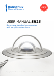
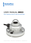
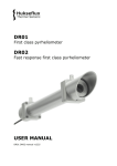
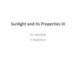
Model 3016
Secondary
Standard
Pyranometer
User’s
Manual
1165 NATIONAL DRIVE
•
SACRAMENTO, CALIFORNIA 95834
•
WWW.ALLWEATHERINC.COM
3 0 1 6
Secondary Standard Pyranometer
TABLE OF CONTENTS
INTRODUCTION ....................................................................................... 1
THEORY OF OPERATION ........................................................................ 2
General Description .............................................................................. 2
Accuracy ............................................................................................... 3
INSTALLATION .......................................................................................... 6
Location ................................................................................................ 6
Mounting ............................................................................................... 6
MAINTENANCE......................................................................................... 9
Recalibration ...................................................................................... 10
CALIBRATION ......................................................................................... 10
SPECIFICATIONS ................................................................................... 11
PARTS LIST ............................................................................................ 13
3016 User’s Manual
ii
3 0 1 6
Secondary Standard Pyranometer
INTRODUCTION
The Model 3016 pyranometer is designed for measuring irradiance (radiant-flux,
Watt/m2) on a plane surface, which results from direct solar radiation and from the
diffuse radiation incident from the hemisphere above. Because the 3016 exhibits
no tilt dependence, it can measure solar radiation on inclined surfaces as well. In
the inverted position, reflected solar radiation can be measured.
For measuring the diffuse component of solar radiation only, the direct solar
component can be shielded semiautomatically from the pyranometer using the
Model 30167 Shadow Ring.
The 3016 pyranometer complies with the specifications for “secondary standards”, the best of three classes as published in the Guide to Meteorological Instruments and Methods of Observation, Fifth Edition, 1983, of the World Meteorological Organization (WMO)—Geneva, Switzerland. The WMO classification list is
adopted, improved, and extended by the International Standard Organization (ISO)
and published as ISO 9060. This standard is one of a series of standards specifying
methods and instruments for the measurement of solar radiation. In this manual,
the specifications for accuracy are listed according to the ISO list.
3016 User’s Manual
1
3 0 1 6
Secondary Standard Pyranometer
THEORY OF OPERATION
General Description
The sensing element of the Model 3016 is a black
painted ceramic disk. 100 thermocouples forming a
thermopile are imprinted on it using thick film techniques. Only the border of the disk is in good thermal contact with the pyranometer body (heatsink),
and the 100 cold junctions are located along this
border. The 100 hot junctions are near the center
in a rotational symmetric arrangement. This fact,
plus a proper leveling of the sensor, results in a low
azimuth error.
When the pyranometer is illuminated, the absorbed radiation results in a radial heat flow to the
border of the disk. The temperature in the center of
the disk will rise due to its thermal resistance. The
temperature difference across the thermal resistance
of the disk is then converted into a voltage.
The temperature rise is easily affected by wind,
rain, and thermal radiation losses to the environment
(“cold” sky). Therefore, the detector is shielded by
two glass domes. Glass domes allow equal transmission of the direct solar component for every position of the sun on the celestial sphere. The spectral
range of the pyranometer is limited by the transmission of the glass. A desiccator in the body prevents dew on the inner side of the domes, which
can cool down considerably on clear, windless nights.
The thermal resistance of the Al2O3 substrate is
relatively low (e.g., an irradiance of 1000 W/m2 results in a rise of center temperature of only 3o C,
and a voltage of 4-6 mV). Natural convection inside the inner dome due to this temperature difference appears to be small, and when tilting a Model
3016, no change of sensitivity is observed.
Other heat flows in the sensing element, e.g. due
to rising or falling body temperature, cause spurious
voltages, sometimes called zero offsets. To compensate for these offsets, a second non-illuminated element is installed, in which the same heat flow will
arise. By anti-series arrangement of both elements,
the spurious voltage is largely cancelled out. The
white plastic screen reduces the body temperature
variations due to solar radiation and (cold) rain showers.
For a given heat flow, the sensitivity of the pyranometer is a function of the thermal conductivity
of the substrate and the thermoelectric power of the
thermocouple materials. These physical quantities
show temperature dependency, and a thermistor is
applied in the electric circuit to keep the sensitivity
constant for temperatures between -10° C and + 40o
C.
The Model 3016’s sensing element responds to
the total power absorbed, and is theoretically nonselective as to the spectral distribution of the radiation. This implies that the naked thermal detector
is also sensitive to long wave infrared radiation (thermal radiation 3000 nm) from the environment.
Figure 1. Model 3016 Construction Detail
2 3016 User’s Manual
3 0 1 6
Secondary Standard Pyranometer
The pyranometer’s sensitivity is cross-correlated to
a number of parameters, such as temperature, level
of irradiance, vector of incidence, etc. The upper limiting values of the resulting sensitivity variations are
listed in the specifications. The Model 3016 qualifies as a “secondary standard” according to World
Meteorological Organization classifications (see
Table 1).
Secondary
Standard
FIrst
Class
Second
Class
Resolution (smallest detectable change in
W/m2)
±1
±5
±10
Stability (percentage of full scale,
change/year)
±1
±2
±5
Cosine response (percentage deviation
from ideal at 10° solar elevation on a clear
day)
<±3
<±7
<±15
Azimuth response (Percentage deviation
from the mean at 10° solar elevation on a
clear day)
<±3
<±5
<±10
Temperature response (percentage
maximum error due to change of ambient
temperature within the operating range)
±1
±2
±5
±0.5
±2
±5
±2
±5
±10
<25 s
<1 min.
<4 min.
Characteristic
of simply measured parameters (sometimes called
transfer function or sensitivity function). This is especially convenient in connection with a programmable data acquisition system.
For the Model 3016, the effect of each parameter on the sensitivity can be shown separately, because the parameters exhibit less interaction.
The non-linearity error—the sensitivity variation
with irradiance—is the same for any given 3016 (see
Figure 2).
1.02
relative sensitivity
Accuracy
1.00
0.98
Non-linearity (percentage of full scale)
Spectral sensitivity (percentage deviation
from mean absorptance 0.3 to 3µm)
Response time (99% response)
500
1000
irradiance (W/m 2)
Figure 2. Non-linearity of Model 3016 pyranometer.
The temperature dependence of the sensitivity
is an individual function. For a given 3016, the curve
is somewhere in the shaded region of Figure 3.
Table 1. WMO pyranometer classifications.
Normally, the supplied sensitivity figure is used
to calculate irradiances. If the operation conditions
differ from calibration conditions, errors in the calculated irradiances must be expected. For a secondary standard instrument, the WMO expects maximum errors in the hourly radiation totals of 3%. In
the daily total, an error of 2% is expected, because
some response variations cancel each other out if the
integration period is long.
These errors can be reduced further if the actual
sensitivity of the pyranometer is used in the conversion of voltage to irradiance. The actual sensitivity
can be calculated when it is a well known function
Figure 3. The curve of relative sensitivity variation with
instrument temperature of a Model 3016 pyranometer is in the
shaded region.
Other effects, such as directional response, spectral selectivity, and zero offset, are more difficult to
correct for. Directional response is an individual feature, and depends on imperfections in the glass
domes and angular reflection properties of the black
paint. A polar diagram of combined cosine and azimuth response (= directional response) of a typical
3016 is shown in Figure 4.
3016 User’s Manual
3
3 0 1 6
Secondary Standard Pyranometer
Spectral selectivity is the product of spectral absorptance of the black coating (see Figure 5) and
spectral transmittance of the glass domes (see Figure 6).
Shifts in the solar spectrum, due to changes from
clear to overcast sky, are mainly in the mid of the
spectral range. No significant spectral selectivity errors have to be expected, e.g. at a sun’s elevation of
30° (airmass 2) only 1% of the solar radiation has
wavelengths below 335 nm and only 1% of the solar radiation has wavelengths above 2200 mm.
Figure 4. Polar diagram of directional response expressed as
the percentage deviation of the ideal proportionally to the cosine
of the zenith angle. In this example, the zenith axis was
perpendicular to the base of the pyranometer and the cable was
pointing to North.
To make corrections on the direct solar radia5. Spectral reflectance of Carbon black coating as
tion with this diagram, the position of the sun on Figure
measure in a UV/VIS/NIR spectrophotometer with integrating
the celestial sphere and the ratio of direct to global sphere attachment.
radiation must be known. Before leaving the factory, the cosine response of each 3016 is measured
roughly. At a certain zenith angle, the “west” cosine
response and “east” cosine response are determined.
The mean of both values is mentioned on the calibration certificate, expressed as percentage deviation
from the ideal proportionality.
Figure 6. 1. Relative spectral transmittance of two pyranometer
domes. (Four surface reflections and index change with
wavelength are taken into account.)
2. Spectral distribution of solar radiation at sea
level. Sun at zenith (Airmass 1).
4 3016 User’s Manual
3 0 1 6
Secondary Standard Pyranometer
Zero Offset
The following definition of zero offset is used:
When the sensor does not absorb radiation with
wavelengths in the spectral range of the instrument
and there still is a signal, we call it zero offset. Two
types of zero offset are distinguished.
Zero Offset I
This zero offset is present when the inner dome has
a temperature other than that of the cold junctions
of the sensor. Practically, this is always the case when
there is a clear sky. Because of the low effective sky
temperature (< 0o C), the earth’s surface emits
roughly 100 W/m2 long wave infrared radiation
upwards. The outer glass dome of a pyranometer
radiates heat in the same way and is cooling down
several degrees below air temperature (the emissivity of glass for the particular wavelength region is
nearly 1). The emitted heat is attracted from the
body (by conduction in the dome), from the air (by
wind) and from the inner dome (through infrared
radiation). The inner dome is cooling down too and
will attract heat from the body by conduction and
from the sensor by the net infrared radiation again.
The latter heat flow is opposite to the heat flow from
absorbed solar radiation and causes the well-known
zero depression at night of approximately -5 W/m2.
This negative zero offset is also present on a clear
day, however, hidden in the solar radiation signal.
During indoor measurements with a solar simulator, the inner dome can become warmer than the
pyranometer body due to net thermal radiation from
the lamp housing. A positive Zero Offset I is the
result. The Zero Offset I can be checked by placing
a light tight (paper) box over the pyranometer. The
response to solar radiation will decay with a time
constant of 5 s, but the dome temperature will go to
equilibrium with a time constant of several minutes.
So, after one minute, the remaining signal is the main
part of the last Zero Offset I.
Good ventilation of domes and body is the solution to decreasing Zero Offset I.
Zero Offset II
This zero offset arises when the body (heatsink) temperature increases or decreases. This results in a temperature difference between the cold junctions (connected to the heatsink) and the hot junctions due to
the heat flow necessary to load or unload the sensor’s
heat capacity. In the 3016, there is principally no
Zero Offset II, because there is a second non-illuminated compensation element.
Upper values of zero offset
Zero Offset I:
7 W/m2 response to 200 W/
m2 thermal radiation (ventilated domes)
12 W/m2 response to 200
W/m 2 thermal radiation
(no ventilation)
Zero Offset II:
< 3 W/m2 response to 5o
C/hr change of body temperature
3016 User’s Manual
5
3 0 1 6
Secondary Standard Pyranometer
INSTALLATION
Location
Ideally, the site for the pyranometer should be free
from any obstructions above the plane of the sensing element and, at the same time, the pyranometer
should be readily accessible to allow cleaning of the
domes and inspection of the desiccator.
If this is not possible, the site should be chosen
in such a way that any obstruction over the azimuth
range between earliest sunrise and latest sunset
should have an elevation not exceeding 5o (the apparent sun diameter is 0.5o). This is important for
an accurate measurement of the direct solar radiation. The diffuse (solar) radiation is less influenced
by obstructions near the horizon. For instance, an
obstruction with an elevation of 5o over the whole
azimuth range of 360o decreases the downward diffuse solar radiation by only 0.8%.
The pyranometer should be located in such a
way that a shadow will not be cast on it at any time
(for example, by masts or exhaust pipes). Mind that
hot (over 200oC) exhausted gas (streams) will produce radiation in the spectral range of the 3016 Pyranometer. The pyranometer should be far from lightcolored walls or other objects likely to reflect sunlight onto it.
Mounting
In principle, no special orientation of the instrument
is required due to the rotational symmetric sensor.
The World Meteorological Organization recommends that the emerging leads are pointed to the
nearest pole to minimize heating of the electrical
connections. However, when a polar diagram of the
combined azimuth and cosine response is available,
the pyranometer may be oriented so that the sun
path lies in the low error region.
6 3016 User’s Manual
The Model 3016 is provided with two holes for
5 mm bolts (e.g., M5 x 60 or M5 x 65 allen head
bolts). The pyranometer should first be secured
lightly with the bolts to a mounting stand or platform. Accurate measurement of global radiation requires proper leveling of the thermopile surface.
Level the instrument by turning the leveling screws
to bring the bubble of the spirit level within the ring.
(For easy leveling, adjust the screw nearest the spirit
level first.) Once the sensor is level, tighten the two
mounting screws.
When the 3016 is leveled horizontally with the
spirit level, or when it is mounted with its base to a
horizontal plane, the thermopile is horizontal within
0.1°. This causes a maximum azimuthal variation of
±1% at a sun’s elevation of 10o.
Since temperature fluctuations of the pyranometer body can produce offset signals (see Appendix
II), the pyranometer body should be thermally isolated from the mounting plate whenever possible.
This can be done using the leveling screws. Electrical contact with ground must be maintained, however, to lead off current induced by lightning.
Installation for Measurement of Solar
Radiation on Inclined Surfaces
It may be necessary to remove the leveling screws
for easy orientation of the sensor parallel to the inclined surface. If the temperature of the mounting
plate is expected to rise considerably (more than 10o
C above air temperature), the body must be thermally isolated from the plate. This will promote a
thermal equilibrium between domes and body and
decrease zero offset signals. The Model 3016 shows
no tilt effect up to irradiances of 1400 W/m2.
3 0 1 6
Secondary Standard Pyranometer
Installation for Measurement of
Reflected Solar Radiation
Installation for Measurement of
Diffuse Radiation
Reflected solar radiation can be measured by installing the 3016 in the inverted position. According to
the WMO, the height should be 1-2 meters above a
surface covered by short cut grass.
The mounting device should not interfere with
the field of view of the instrument. A setup such as
that shown in Figure 7 is suitable. The upper screen
prevents excessive heating of the pyranometer body
by solar radiation. The lower screen prevents direct
illumination of the domes by the sun at sunrise and
sunset.
For measuring sky radiation, direct solar radiation
is best intercepted by a small metal disk. The shadow
of the disk must cover the pyranometer domes completely. However, to follow the sun’s apparent motion, a power drive equatorial device is necessary.
Simpler is the use of a shadow ring (Model
30167). The shadow ring blocks direct radiation,
allowing only diffuse radiation to reach the pyranometer. To compensate for seasonal changes, the
shadow ring must be adjusted periodically.
Underwater Use
The 3016 pyranometer is in principle watertight.
However, the hemispherical air-cavity under the
domes acts as a negative lens. The parallel beam of
direct solar radiation becomes divergent after passing through the outer dome, an effect known as
“defocusing”. Consequently, the intensity at the
sensor is much less than that outside the pyranometer. The sensitivity figure is not valid in this case.
Electrical Connection
The 3016 is provided with a 10 m cable with shield
and three leads. The color code is:
Figure 7. Measuring Reflected Solar Radiation
Offset signals generated in the pyranometer by
thermal effects are a factor of 5 more disturbing in
the measurement of the reflected radiation due to
the lower irradiance level. The mast shown in Figure 7 intercepts a fraction D/2þS of the radiation
coming from the ground. In the most unfavorable
situation (sun at zenith), the pyranometer shadow
decreases the signal with a part R2/H2.
red
blue
white
plus
minus
case
The shield is isolated from the case with a surge
arrestor, so no shield current can exist. Shield and
white leads may be connected to the same ground
at the readout equipment. The cable must be firmly
secured to minimize spurious response during stormy
weather. (Pressing the cable produces voltage spikes,
a triboelectric effect and capacitance effect.) The
3016’s cables are made of selected materials with
minimal triboelectric effect.
3016 User’s Manual
7
3 0 1 6
Secondary Standard Pyranometer
Take care that the “+” and “-” terminals at the
junction box have the same temperature, to prevent
thermal EMFs. A box or connector with a metal
outer case is advised.
The temperature dependency of the pyranometer can be increased by readout equipment loading
the thermistor circuit and thermopiles. The sensitivity is affected more than 1% when the load resistance is under 150 kOhm. For this reason, readout
equipment with input impedances of 1 Megohm or
more, such as potentiometric recorders, digital voltmeters, etc., should be used.
The application of attenuator circuits to modify
the calibration factor is not recommended, because
this will also affect the temperature response of the
sensor. However, recorders with a variable voltage
range can be set so that the result can be read directly in W/m2.
A large input bias current at the readout equipment can produce a voltage of several microvolts
across the impedance of the pyranometer. The correct pen’s zero can be adjusted by replacing the
pyranometer’s impedance with a resistance at the
input terminals.
The pyranometer can be connected to a computer or data acquisition system as well. A low voltage analog input module with A/D converter must
be available. The span and resolution of the A/D
converter in the module must allow a system sensitivity of about 1 bit per W/m2. More resolution is
not necessary during outdoor solar radiation measurements, because pyranometers exhibit offsets up
to ±2 W/m2 due to a lack of thermal equilibrium.
Many types of amplifiers are available, such as
those used for temperature measurement, for amplification of the pyranometer’s signal.
A surge arrester is incorporated into the sensor
to lead off induced lightning current to the case. For
this reason, the case should be grounded. The surge
arrester is noble gas filled, has infinite impedance,
and recovers after breakdown. The breakdown voltage is 90 V, and the peak pulse current is 10 kA.
Figure 8. Model 3016 Electrical Connection
8 3016 User’s Manual
3 0 1 6
Secondary Standard Pyranometer
MAINTENANCE
Once installed, the pyranometer requires little maintenance. The outer dome should be inspected at
regular intervals and cleaned regularly, preferably
every morning.
On clear windless nights, the outer dome temperature of horizontally placed pyranometers will decrease—even to the dew point temperature of the
air—due to IR radiation exchange with the cold sky.
(The effective sky temperature can be 30oC lower
than the ground temperature, which results in an
infrared emission of -150 W/m2.) When this happens, dew, glazed frost, or hoar frost may form on
the top of the outer dome, and may remain there
for several hours during the morning. An ice cap on
the dome is a strong diffuser and increases the
pyranometer’s signal drastically, up to 50% in the
first hours after sunrise.
In some networks, the exposed dome of the pyranometer is ventilated continuously by a blower to
keep the dome above the dew point temperature.
This ventilation also decreases the sensitivity to thermal radiation (zero offset I) by an approximate factor of two.
When the blue silica gel in the drying cartridge
turns completely pink (normally after several
months), it must be replaced with active material.
Pink silica gel can be dried out and reactivated by
placing it in an oven at 130oC for several hours.
3016 User’s Manual
9
3 0 1 6
Secondary Standard Pyranometer
CALIBRATION
The ideal pyranometer should always have a constant ratio of voltage output/irradiance level (outside the instrument, in the plane of the sensing element). This ratio is called sensitivity or responsivity.
The irradiance value can be simply computed
by dividing the output signal of the pyranometer by
its sensitivity figure, or by multiplying the signal
value by the reciprocal of the sensitivity figure (often called calibration factor).
The sensitivity figure of a particular pyranometer is an individual one, determined in the
manufacturer’s laboratory by comparison against a
standard pyranometer.
The standard pyranometer is calibrated outdoors
regularly at a Radiation Center. Naturally, the spectral content of the laboratory lamp differs from the
outdoor solar spectrum at the Radiation Center.
However, this has no consequences for the transfer
of calibration, since the standard and unknown pyranometers both have the same black coating and glass
domes.
The supplied sensitivity figure is valid for the
following conditions:
• An ambient temperature of 20o C.
• For a horizontal pyranometer as well as for
a tilted pyranometer.
• Normal incident radiation of 500 W/m2.
• Spectral content as clear sky solar radiation.
Radiometric Reference embodied by several absolute pyrheliometers (black body cavity type) maintained in Davos, Switzerland.
There are several procedures for transferring calibration from a narrow field of view instrument
(pyrheliometer) to a wide field of view instrument
(pyranometer). One method eliminates the direct
component of solar radiation temporarily from the
pyranometer by shading the whole outer dome of
the instrument with a disk.
In another procedure, the unknown pyranometer remains in its normal operating condition. This
“component” method involves measuring the direct
component with a pyrheliometer and the diffuse
component with a disk-shaded pyranometer. The
diffuse radiance is only about 10% of the global radiation, as is the case on a clear day, and the sensitivity of the second pyranometer does not need to
be known very accurately. Both procedures are suited
to obtaining a working standard pyranometer.
Transfer from the working standard pyranometer to other pyranometers can be done in sunlight.
The pyranometers must be mounted side by side so
that each views the same sky dome. It is desirable to
integrate or average the outputs over a period of time,
and then compute the calibration constants on the
basis of these averages. This reduces the errors due
to changing parameters during the day. Transfer
from another pyranometer in the laboratory is only
possible when both pyranometers are of the same
Recalibration
type and have the same glass domes and optical coatPyranometer sensitivity changes with time and with
ings.
exposure to radiation, often due to deterioration of
Details of calibration methods are found in the
the black paint. Periodic calibration (at least every
WMO guide.
two years) is advised. Accurate calibrations can be
done outdoors under clear conditions by reference
to a standard pyrheliometer. Many National
Weather Services have calibration facilities. Their
standard pyrheliometer is compared with the World
10 3016 User’s Manual
3 0 1 6
Secondary Standard Pyranometer
SPECIFICATIONS
Performance
Response time for 95% response
Zero offset
a) response to 200 Wm2 net thermal radiation (ventilated)
b) response to 5 K h-1 change in ambient temperature
Non-stability percentage change responsivity per year
Non-linearity percentage deviation from the
responsivity at 500 Wm-2 due to the change
in irradiance within 100 Wm-2 to 1000 Wm-2
Directional response for beam
radiation. The range of errors caused
by assuming that the normal incidence
responsivity is valid for all directions
when measuring from any direction a beam
radiation whose normal incidence
irradiation is 100 Wm-2
Spectral selectivity percentage
deviation of the product of spectral
absorptance and spectral transmittance
from the corresponding mean within 0, 35
µm and 1, 5 µm
Temperature response percentage
deviation due to change in ambient
temperature from -10 to +40° C relative to
20° C
Tilt response percentage deviation
from the responsivity at 0o tilt
(horizontal) due to change in tilt from
0o to 90o at 1000 Wm-2 irradiance
Viewing angle
Irradiance
Spectral range
Sensitivity
Impedance
< 15 s
+ 7 Wm-2
+ 2 Wm-2
+ 0.5%
+ 0.6%
+ 10 Wm-2
+ 2%
+ 1%
+ 0.25%
2þ sr
0-1400 W/m2 (max 4000 W/m2)
305-2800 nm (50% points)
335-2200 nm (95% points)
Between 4 and 6 µV/Wm-2
700-1500 Ohm
3016 User’s Manual
11
3 0 1 6
Secondary Standard Pyranometer
Construction
Receiver paint
Glass domes
Desiccant
Spirit level
Materials
Weight
Cable length
Dimensions
Figure 9. Model 3016 Secondary Standard
Pyranometer
12 3016 User’s Manual
Carbon black
Schott K5 optical glass 2 mm thick,
30 mm and 50 mm outer diameter
Silica gel
Sensitivity 0.1 degree (bubble half out
of the ring) coincide with base of the
instrument. Detector surface and base
are coplanar within 0.1o.
Anodized aluminum case, stainless steel
screws in stainless steel bushes, white plastic screen of ASA, drying cartridge PMMA
830 g
10 m
See Figure 9
3 0 1 6
Secondary Standard Pyranometer
PARTS LIST
Model 3016 Replaceable Parts
and Options
Description
Desiccator cartridge
White sun shield
Rubber ring for outer
glass dome
Outer glass dome
with metal ring
Levelling screw
Fixed mounting foot
Shadow Ring
Part Number
30161
30162
30163
30164
30165
30166
30167
3016 User’s Manual
13
All Weather Inc.
1165 National Drive
Sacramento, CA 95818
Fax: 916.928.1165
Phone: 916.928.1000
Toll Free: 800.824.5873
www.allweatherinc.com
3016-001
ECN 4476
July, 1995