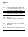
1
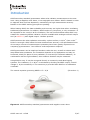
Hukseflux
Thermal Sensors
USER MANUAL SR25
Secondary standard pyranometer
with sapphire outer dome
Copyright by
by Hukseflux
Hukseflux || manual
manual v1508
v1508 || www.hukseflux.com
www.hukseflux.com || [email protected]
[email protected]
Copyright
Warning statements
Putting more than 12 Volt across the sensor wiring
can lead to permanent damage to the sensor.
Do not use “open circuit detection” when measuring
the sensor output.
SR25 manual v1508
2/47
Contents
Warning statements
Contents
List of symbols
Introduction
Ordering and checking at delivery
1
Ordering SR25
1.1
Included items
1.2
Quick instrument check
1.3
Instrument principle and theory
2
Specifications of SR25
3
Specifications of SR25
3.1
Dimensions of SR25
3.2
Standards and recommended practices for use
4
Classification standard
4.1
General use for solar radiation measurement
4.2
General use for sunshine duration measurement
4.3
Specific use for outdoor PV system performance testing
4.4
Specific use in meteorology and climatology
4.5
Installation of SR25
5
Site selection and installation
5.1
Installation of the sun screen
5.2
Electrical connection
5.3
Requirements for data acquisition / amplification
5.4
Making a dependable measurement
6
The concept of dependability
6.1
Reliability of the measurement
6.2
Speed of repair and maintenance / instrument lifetime
6.3
Uncertainty evaluation
6.4
Maintenance and trouble shooting
7
Recommended maintenance and quality assurance
7.1
Trouble shooting
7.2
Calibration and checks in the field
7.3
Data quality assurance
7.4
Appendices
8
Appendix on heating SR25
8.1
Appendix on cable extension / replacement
8.2
Appendix on tools for SR25
8.3
Appendix on spare parts for SR25
8.4
Appendix on standards for classification and calibration
8.5
Appendix on calibration hierarchy
8.6
Appendix on meteorological radiation quantities
8.7
Appendix on ISO and WMO classification tables
8.8
Appendix on definition of pyranometer specifications
8.9
8.10 Appendix on terminology / glossary
8.11 Appendix on conditions of sale: warranty and liability
8.12 EC declaration of conformity
SR25 manual v1508
2
3
4
5
8
8
8
9
10
13
13
16
17
17
17
17
18
18
19
19
20
21
22
23
23
24
25
26
28
28
29
30
31
33
33
36
37
37
38
39
40
41
42
43
44
45
3/47
List of symbols
Quantities
Symbol
Unit
Voltage output
Sensitivity
Sensitivity at reference conditions
Temperature
Electrical resistance
Solar irradiance
Solar radiant exposure
Time in hours
U
S
S0
T
Re
E
H
h
V
V/(W/m2)
V/(W/m2)
°C
Ω
W/m2
W∙h/m2
h
Temperature coefficient
Temperature coefficient
Temperature coefficient
a
b
c
1/°C²
1/°C
-
(see also appendix 8.7 on meteorological quantities)
Subscripts
Not applicable
SR25 manual v1508
4/47
Introduction
SR25 secondary standard pyranometer takes solar radiation measurement to the next
level. Using a sapphire outer dome, it has negligible zero offsets. SR25 is heated in order
to suppress dew and frost deposition, maintaining its high measurement accuracy.
Patents on the SR25 working principle are pending.
When heating SR25, the data availability and accuracy are higher than when ventilating
traditional pyranometers. In addition, SR25 needs very low power; it only consumes 1.5
W compared to the usual 10 W for ventilation. The low thermal offsets make SR25 very
suitable for measuring diffuse radiation. SR25 is available with analogue millivolt output
and (as SR25-D1) with digital output - Modbus protocol.
SR25 measures the solar radiation received by a plane surface, in W/m2, from a 180 o
field of view angle. SR25 offers the best measurement accuracy: the specification limits
of two major sources of measurement uncertainty have been greatly improved over
competing pyranometers: “zero offset a” and temperature response.
SR25 pyranometer can be employed outdoors under the sun, as well as indoors with
lamp-based solar simulators. Its orientation depends on the application and may be
horizontal, tilted (for plane of array radiation) or inverted (for reflected radiation). In
combination with the right software, also sunshine duration may be measured.
Using SR25 is easy. It can be connected directly to commonly used data logging
systems. The irradiance, E, in W/m2 is calculated by dividing the SR25 output, a small
voltage U, by the sensitivity S. The sensitivity is provided with SR25 on its calibration
certificate.
The central equation governing SR25 is: E = U/S
(Formula 0.1)
Figure 0.1 SR25 secondary standard pyranometer with sapphire outer dome
SR25 manual v1508
5/47
SR25’s low temperature dependence makes it an ideal candidate for use under very cold
and very hot conditions. The temperature dependence of every individual instrument is
tested and supplied as a second degree polynomial. This information can be used for
further reduction of temperature dependence during post-processing. In case the
sensitivity is corrected for the instrument body temperature, the optional measurement
equation becomes:
E = U/(S 0 ·(a·T² + b·T +c))
(Formula 0.2)
The temperature coefficients a, b, and c can be found on the calibration certificate of
each instrument.
SR25 has the following distinguishing features and benefits:
• sapphire outer dome: negligible zero offsets
• internal heater: because of dew and frost suppression by heating, better data
availability and accuracy than ventilated instruments
• 1.5 W: very low power consumption
• test certificates for temperature response and directional response included: all
sensors tested individually for ISO 9060 compliance
The instrument should be used in accordance with the recommended practices of ISO,
WMO and ASTM.
The ASTM E2848 “Standard Test Method for Reporting Photovoltaic Non-Concentrator
System Performance” (issued end 2011) confirms that a pyranometer is the preferred
instrument for PV system performance monitoring. SR25 pyranometer complies with the
requirements of this standard. For more information see our pyranometer selection
guide.
WMO has approved the “pyranometric method” to calculate sunshine duration from
pyranometer measurements in WMO-No. 8, Guide to Meteorological Instruments and
Methods of Observation. This implies that SR25 may be used, in combination with
appropriate software, to estimate sunshine duration. This is much more cost-effective
than using a dedicated sunshine duration sensor. Ask for our application note.
Suggested use for SR25:
•
•
•
•
•
•
•
all situations where ventilated pyranometers are employed
PV system performance monitoring
indoor PV testing with solar simulators
airborne measurements
diffuse measurements
environments with dew
environments with frost
SR25 manual v1508
6/47
Model SR25-D1 outputs irradiance digitally. SR25-D1 uses a high-end A/D converter and
the industry standard Modbus RTU over 2-wire RS-485 communication protocol.
This user manual covers SR25 use. Specifications of model SR25-D1, the
secondary standard pyranometer with digital output, differ from those of SR25.
For SR25-D1 use, please consult the SR25-D1 user manual.
SR25 manual v1508
7/47
1
Ordering and checking at delivery
1.1
Ordering SR25
The standard configuration of SR25 is with 5 metres cable.
Common options are:
•
•
•
Longer cable (in multiples of 5 m). Specify total cable length.
Internal temperature sensor. This can be either a Pt100 or a 10 kΩ thermistor.
Specify respectively T1 or T2.
Five silica gel bags in an air-thight bag for SR25 desiccant holder. Specify order
number DC01.
Supply of products is subject to Hukseflux’ General Conditions of Sale. The product
warranty (involving repair or replacement without charge for product or working hours) is
24 months.
Hukseflux does not accept any liability for losses or damages related to use of the
supplied products. See the appendix and Hukseflux’ General Conditions of Sale for
detailed statements on warranty and liability.
1.2
Included items
Arriving at the customer, the delivery should include:
•
•
•
•
•
•
pyranometer SR25
sun screen
cable of the length as ordered
calibration certificate matching the instrument serial number
product certificate matching the instrument serial number (including temperature
response and directional response test)
any other options as ordered
Please store the certificates in a safe place.
SR25 manual v1508
8/47
1.3
Quick instrument check
A quick test of the instrument can be done by using a simple hand held multimeter and a
lamp.
1. Check the electrical resistance of the sensor between the green (-) and white (+) wire.
Use a multimeter at the 1000 Ω range. Measure the sensor resistance first with one
polarity, than reverse the polarity. Take the average value. The typical resistance of the
wiring is 0.1 Ω/m. Typical resistance should be the typical sensor resistance of 100 to
200 Ω plus 1.5 Ω for the total resistance of two wires (back and forth) of each 5 m.
Infinite resistance indicates a broken circuit; zero or a low resistance indicates a short
circuit.
2. Check if the sensor reacts to light: put the multimeter at its most sensitive range of
DC voltage measurement, typically the 100 x 10-3 VDC range or lower. Expose the sensor
to a strong light source, for instance a 100 W light bulb at 0.1 m distance. The signal
should read > 2 x 10⁻³ V now. Darken the sensor either by putting something over it or
switching off the light. The instrument voltage output should go down and within one
minute approach 0 V.
3. Remove the sun screen, (see chapter on installation of the sun screen). Inspect the
bubble level.
4. Inspect the instrument for any damage.
5. Inspect if the humidity indicator is blue. Blue indicates dryness. The colour pink
indicates it is humid: in the latter case replace the desiccant (see chapter on
maintenance).
SR25 manual v1508
9/47
2
Instrument principle and theory
3
4
5
2
6
1
7
11
8
10
9
Figure 2.1 Overview of SR25:
(1)
(2)
(3)
(4)
(5)
(6)
(7)
(8)
(9)
(10)
(11)
cable (standard length 5 metres, optional longer cable)
fixation of sun screen (thumb screw)
glass inner dome
thermal sensor with black coating
sapphire outer dome
sun screen
humidity indicator
desiccant holder
levelling feet
bubble level
connector
SR25 manual v1508
10/47
SR25’s scientific name is pyranometer. A pyranometer measures the solar radiation
received by a plane surface from a 180° field of view angle. This quantity, expressed in
W/m2, is called “hemispherical” solar radiation. The solar radiation spectrum extends
roughly from 285 to 3000 x 10-9 m. By definition a pyranometer should cover that
spectral range with a spectral selectivity that is as “flat” as possible.
In an irradiance measurement by definition the response to “beam” radiation varies with
the cosine of the angle of incidence; i.e. it should have full response when the solar
radiation hits the sensor perpendicularly (normal to the surface, sun at zenith, 0° angle
of incidence), zero response when the sun is at the horizon (90° angle of incidence, 90°
zenith angle), and 50 % of full response at 60° angle of incidence.
A pyranometer should have a so-called “directional response” (older documents mention
“cosine response”) that is as close as possible to the ideal cosine characteristic.
In order to attain the proper directional and spectral characteristics, a pyranometer’s
main components are:
•
a thermal sensor with black coating. It has a flat spectrum covering the 200 to 50000
x 10-9 m range, and has a near-perfect directional response. The coating absorbs all
solar radiation and, at the moment of absorption, converts it to heat. The heat flows
through the sensor to the sensor body. The thermopile sensor generates a voltage
output signal that is proportional to the solar irradiance.
•
a sapphire (outer) dome. The high thermal conductivity of the sapphire outer dome
ensures excellent thermal coupling between body and outer dome, even when the
pyranometer is heated. As a result, both zero offset a and heating offset are very low.
•
a second (inner) dome made of glass. This dome limits the spectral range from 285
to 3000 x 10-9 m (cutting off the part above 3000 x 10-9 m), while preserving the
180° field of view angle. For a secondary standard pyranometer, two domes are
used, and not one single dome. This construction provides an additional “radiation
shield”, resulting in a better thermal equilibrium between the sensor and inner dome,
compared to using a single dome. The effect of having a second dome is a further
reduction of instrument offsets.
Pyranometers can be manufactured to different specifications and with different levels of
verification and characterisation during production. The ISO 9060 - 1990 standard, “Solar
energy - specification and classification of instruments for measuring hemispherical solar
and direct solar radiation”, distinguishes between 3 classes; secondary standard (highest
accuracy), first class (second highest accuracy) and second class (third highest
accuracy).
From second class to first class and from first class to secondary standard, the achievable
accuracy improves by a factor 2.
SR25 manual v1508
11/47
relative spectral content /
response [arbitrary units]
1,2
1
solar radiation
0,8
pyranometer
response
0,6
0,4
0,2
0
100
1000
10000
wavelength [x 10-9 m]
Figure 2.2 Spectral response of the pyranometer compared to the solar spectrum. The
pyranometer only cuts off a negligible part of the total solar spectrum.
Deviation from ideal cosine behaviour [%]
4%
North
2%
0%
East
South
0
20
40
60
80
West
-2%
ISO secondary
standard
directional
response limit
-4%
zenith angle [°]
Figure 2.3 Directional response of a SR25 pyranometer of 4 azimuth angles, compared
to secondary standard limits
SR25 manual v1508
12/47
3
Specifications of SR25
3.1
Specifications of SR25
SR25 is a pyranometer of the highest category in the ISO 9060 classification system:
secondary standard. It measures the solar radiation received by a plane surface from a
180o field of view angle. This quantity, expressed in W/m2, is called “hemispherical” solar
radiation. Working completely passive, using a thermopile sensor, SR25 generates a
small output voltage proportional to this flux. It can only be used in combination with a
suitable measurement system.
SR25 has an onboard heater and a temperature sensor. Heating the sensor, measuring
the body temperature and using the correction of the temperature response, all
contribute to the dependability and accuracy of the measurement. However, also when
not using these features, SR25 still complies with the secondary standard requirements.
The instrument should be used in accordance with the recommended practices of ISO,
IEC, WMO and ASTM.
Table 3.1.1 Specifications of SR25 (continued on next pages)
SR25 MEASUREMENT SPECIFICATIONS:
LIST OF CLASSIFICATION CRITERIA OF ISO 9060*
ISO classification (ISO 9060: 1990)
WMO performance level (WMO-No. 8,
seventh edition 2008)
Response time (95 %)
Zero offset a (response to 200 W/m2
net thermal radiation)
Zero offset b (response to 5 K/h
change in ambient temperature)
Non-stability
Non-linearity
Directional response
Directional response test of individual
instrument
Spectral selectivity
Temperature response
Temperature response of individual
instrument
Tilt response
secondary standard pyranometer
high quality pyranometer
3s
1 W/m2 unventilated
1 W/m2 ventilated
< ± 2 W/m2
< ± 0.5 % change per year
< ± 0.2 % (100 to 1000 W/m2)
< ± 10 W/m2
report included
< ± 3 % (0.35 to 1.5 x 10⁻⁶ m)
< ± 1 % (-10 to +40 °C)
< ± 0.4 % (-30 to +50 °C) with correction in dataprocessing
report included
< ± 0.2 % (0 to 90 ° at 1000 W/m2)
*For the exact definition of pyranometer ISO 9060 specifications see the appendix.
SR25 manual v1508
13/47
Table 3.1.1 Specifications of SR25 (continued)
SR25 ADDITIONAL SPECIFICATIONS
Measurand
Measurand in SI radiometry units
Optional measurand
Field of view angle
Measurement range
Sensitivity range
Sensitivity (nominal)
Expected voltage output
Measurement function / required
programming
Optional measurement function /
required programming for correction of
sensitivity as a function of instrument
body temperature
Measurement function / optional
programming for sunshine duration
Required readout
Internal temperature sensor
Optional readout
Rated operating temperature range
Sensor resistance range
Required sensor power
Spectral range
(20 % transmission points)
Standard governing use of the
instrument
Standard cable length (see options)
Cable diameter
Chassis connector
Chassis connector type
Cable connector
Cable connector type
Connector protection class
Cable replacement
Mounting
Levelling
Levelling accuracy
Desiccant
Humidity indicator
IP protection class
SR25 manual v1508
hemispherical solar radiation
irradiance in W/m2
sunshine duration
180 °
0 to 4000 W/m2
7 to 25 x 10-6 V/(W/m2)
12 x 10-6 V/(W/m2)
application under natural solar radiation: -0.1 to + 50
x 10-3 V
E = U/S
E = U/(S 0 ·(a·T²+b·T+c))
programming according to WMO guide paragraph
8.2.2
1 differential voltage channel or 1 single ended
voltage channel, input resistance > 106 Ω
measuring the body temperature:
version code = T1 for Pt100 DIN class A,
version code = T2 for thermistor 10 kΩ at 25 °C
1 temperature channel in case the temperature sensor
is used
-40 to +80 °C
100 to 200 Ω
zero (passive sensor)
285 to 3000 x 10-9 m
ISO/TR 9901:1990 Solar energy -- Field pyranometers
-- Recommended practice for use
ASTM G183 - 05 Standard Practice for Field Use of
Pyranometers, Pyrheliometers and UV Radiometers
5m
5.3 x 10⁻³ m
M16 panel connector, male thread, 10-pole
HUMMEL AG 7.840.200.000 panel connector, front
mounting, short version
M16 straight connector, female thread, 10-pole
HUMMEL AG 7.810.300.00M straight connector,
female thread, for cable 3 to 6 x 10⁻³ m, special
version
IP 67 / IP 69 K per EN 60 529 (connected)
replacement cables with connector can be ordered
separately from Hukseflux
2 x M5 bolt at 65 x 10-3 m centre-to-centre distance
on north-south axis, or 1 x M6 bolt at the centre of
the instrument, connection from below under the
bottom plate of the instrument
bubble level and adjustable levelling feet are included
< 0.1° bubble entirely in ring
two bags of silica gel, 0.5 g, 35 x 20 mm
blue when dry, pink when humid
IP 67
14/47
Table 3.1.1 Specifications of SR25 (started on previous pages)
Gross weight including 5 m cable
Net weight including 5 m cable
Packaging
2.05 kg
0.85 kg
HPRC casing of 255 x 225 x 165 mm
Heater operation
the heater is not necessarily switched on;
recommended operation is to continually power the
heater (see appendix 8.1)
1.5 W at 12 VDC (the heater is not necessarily active)
95 Ω
0 to -1.5 W/m2
HEATING
Required heater power
Heater resistance
Steady state zero offset caused by
heating
CALIBRATION
Calibration traceability
Calibration hierarchy
Calibration method
Calibration uncertainty
Recommended recalibration interval
Reference conditions
Validity of calibration
MEASUREMENT ACCURACY
Uncertainty of the measurement
VERSIONS / OPTIONS
Digital output – Modbus protocol
Longer cable, in multiples of 5 m
ACCESSORIES
Ventilation unit
Separate amplifiers
Hand-held read-out unit
Bags of silica gel for desiccant
SR25 manual v1508
to WRR
from WRR through ISO 9846 and ISO 9847, applying
a correction to reference conditions
indoor calibration according to ISO 9847, Type IIc
< 1.2 % (k = 2)
2 years
20 °C, normal incidence solar radiation, horizontal
mounting, irradiance level 1000 W/m2
based on experience the instrument sensitivity will not
change during storage. During use under exposure to
solar radiation the instrument “non-stability”
specification is applicable.
statements about the overall measurement
uncertainty can only be made on an individual basis.
See the chapter on uncertainty evaluation
option code = D1
for specifications see the SR25-D1 user manual
option code = total cable length
VU01
AC100 and AC420
LI19
set of 5 bags in an air tight bag
option code = DC01
15/47
3.2
Dimensions of SR25
Ø 150
65
M6
85
M5 (2x)
Figure 3.2.1 Dimensions of SR25 in x 10-3 m.
SR25 manual v1508
16/47
4
Standards and recommended practices
for use
Pyranometers are classified according to the ISO 9060 standard and the WMO-No. 8
Guide. In any application the instrument should be used in accordance with the
recommended practices of ISO, IEC, WMO and / or ASTM.
4.1
Classification standard
Table 4.1.1 Standards for pyranometer classification. See the appendix for definitions of
pyranometer specifications, and a table listing the specification limits.
STANDARDS FOR INSTRUMENT CLASSIFICATION
ISO STANDARD
EQUIVALENT
ASTM STANDARD
WMO
ISO 9060:1990
Solar energy -- specification and
classification of instruments for
measuring hemispherical solar and
direct solar radiation
Not available
WMO-No. 8; Guide to
Meteorological Instruments
and Methods of Observation,
chapter 7, measurement of
radiation, 7.3 measurement
of global and diffuse solar
radiation
4.2
General use for solar radiation measurement
Table 4.2.1 Standards with recommendations for instrument use in solar radiation
measurement
STANDARDS FOR INSTRUMENT USE FOR HEMISPHERICAL SOLAR RADIATION
ISO STANDARD
EQUIVALENT
ASTM STANDARD
WMO
ISO/TR 9901:1990
Solar energy -- Field
pyranometers -- Recommended
practice for use
ASTM G183 - 05
Standard Practice for Field
Use of Pyranometers,
Pyrheliometers and UV
Radiometers
WMO-No. 8; Guide to
Meteorological Instruments
and Methods of Observation,
chapter 7, measurement of
radiation, 7.3 measurement
of global and diffuse solar
radiation
4.3
General use for sunshine duration measurement
According to the World Meteorological Organization (WMO, 2003), sunshine duration
during a given period is defined as the sum of that sub-period for which the direct solar
irradiance exceeds 120 W/m2.
SR25 manual v1508
17/47
WMO has approved the “pyranometric method” to estimate sunshine duration from
pyranometer measurements (Chapter 8 of the WMO Guide to Instruments and
Observation, 2008). This implies that a pyranometer may be used, in combination with
appropriate software, to estimate sunshine duration. Ask for our application note.
Table 4.3.1 Standards with recommendations for instrument use in sunshine duration
measurement
STANDARDS FOR INSTRUMENT USE FOR SUNSHINE DURATION
WMO
WMO-No. 8; Guide to Meteorological Instruments and Methods of Observation, chapter 8,
measurement of sunshine duration, 8.2.2 Pyranometric Method
4.4
Specific use for outdoor PV system performance testing
SR25 is very well applicable in outdoor PV system performance testing. See also
Hukseflux model SR25-D1 “Digital secondary standard pyranometer with sapphire outer
dome” and SR20-D1 ““Digital secondary standard pyranometer – Modbus protocol”.
Table 4.4.1 Standards with recommendations for instrument use in PV system
performance testing
STANDARDS ON PV SYSTEM PERFORMANCE TESTING
IEC / ISO STANDARD
EQUIVALENT ASTM STANDARD
IEC 61724; Photovoltaic system performance
monitoring – guidelines for measurement, data
exchange and analysis
ASTM 2848-11; Standard Test Method for
Reporting Photovoltaic Non-Concentrator
System Performance
COMMENT: Allows pyranometers or reference
cells according to IEC 60904-2 and -6.
Pyranometer reading required accuracy better
than 5% of reading (Par 4.1)
COMMENT: confirms that a pyranometer is the
preferred instrument for outdoor PV testing.
Specifically recommends a “first class”
pyranometer (paragraph A 1.2.1.)
COMMENT: equals JISC 8906 (Japanese
Industrial Standards Committee)
4.5
Specific use in meteorology and climatology
The World Meteorological Organization (WMO) is a specialised agency of the United
Nations. It is the UN system's authoritative voice on the state and behaviour of the
earth's atmosphere and climate. WMO publishes WMO-No. 8; Guide to Meteorological
Instruments and Methods of Observation, in which a table is included on “level of
performance” of pyranometers. Nowadays WMO conforms itself to the ISO classification
system.
SR25 manual v1508
18/47
5
Installation of SR25
5.1
Site selection and installation
Table 5.1.1 Recommendations for installation of pyranometers
Location
the situation that shadows are cast on the instruments
is usually not desirable. The horizon should be as free
from obstacles as possible. Ideally there should be no
objects between the course of the sun and the
instrument.
Mechanical mounting / thermal insulation
preferably use connection by bolts to the bottom plate
of the instrument. A pyranometer is sensitive to
thermal shocks. Do not mount the instrument with the
body in direct thermal contact to the mounting plate
(so always use the levelling feet also if the mounting
is not horizontal), do not mount the instrument on
objects that become very hot (black coated metal
plates).
Instrument mounting with 2 bolts
2 x M5 bolt at 65 x 10-3 m centre to centre distance
on north-south axis, connection from below under the
bottom plate of the instrument.
Instrument mounting with one bolt
1 x M6 bolt at the centre of the instrument,
connection from below under the bottom plate of the
instrument.
Performing a representative
measurement
the pyranometer measures the solar radiation in the
plane of the sensor. This may require installation in a
tilted or inverted position. The black sensor surface
(sensor bottom plate) should be mounted parallel to
the plane of interest.
In case a pyranometer is not mounted horizontally or
in case the horizon is obstructed, the
representativeness of the location becomes an
important element of the measurement. See the
chapter on uncertainty evaluation.
Levelling
in case of horizontal mounting only use the bubble
level and levelling feet. For inspection of the bubble
level the sun screen must be removed.
Instrument orientation
by convention with the cable exit pointing to the
nearest pole (so the cable exit should point north in
the northern hemisphere, south in the southern
hemisphere).
Installation height
in case of inverted installation, WMO recommends a
distance of 1.5 m between soil surface and sensor
(reducing the effect of shadows and in order to obtain
good spatial averaging).
SR25 manual v1508
19/47
5.2
Installation of the sun screen
SR25’s sun screen can be installed and removed by using the dedicated thumb screw.
See item 2 of the drawing below. The thumb screw can be turned without tools for
fixation or loosening of the sun screen, as visualised below. Once the thumb screw has
turned the sun screen loose, the screen can be lifted off manually. After removal the user
may inspect the bubble level, item 10 of the drawing, and remove the cable / connector,
item 11.
3
4
5
2
6
1
7
11
10
9
8
Figure 5.2.1 Installation and removal of SR25’s sun screen
SR25 manual v1508
20/47
5.3
Electrical connection
In order to operate, a pyranometer should be connected to a measurement system,
typically a so-called datalogger. SR25 is a passive sensor that does not need any power.
Cables generally act as a source of distortion, by picking up capacitive noise. We
recommend keeping the distance between a datalogger or amplifier and the sensor as
short as possible. For cable extension, see the appendix on this subject.
Table 5.3.1 The electrical connection of SR25 versions T1 and T2. The heater is not
necessarily used. The temperature sensor is not necessarily used.
PIN
WIRE
SR25-T1
SR25-T2
2
Red
Pt100 [+]
10 kΩ thermistor [+]
3
Pink
Pt100 [+]
10 kΩ thermistor [+]
6
Blue
Pt100 [−]
10 kΩ thermistor [−]
8
Grey
Pt100 [−]
10 kΩ thermistor [−]
1
Brown
heater
heater
4
Yellow
heater
heater
9
Black
ground
ground
7
White
signal [+]
signal [+]
5
Green
signal [−]
signal [−]
Note 1: Pt100’s of version T1 may be connected in a 3-wire or 4-wire configuration.
Note 2: 10k thermistors of version T2 are usually connected in a 2-wire configuration.
Note 3: the heater is not necessarily connected. In case it is connected, the polarity of
the connection is not important.
Note 4: signal wires are insulated from ground wire and from the sensor body. Insulation
resistance is tested during production and larger than 1 x 10⁶ Ω.
Note 5: ground is connected to the connector, the sensor body and the shield of the wire.
Figure 5.3.1 Electrical diagram of the internal wiring of SR25. The shield is connected to
the sensor body.
SR25 manual v1508
21/47
5.4
Requirements for data acquisition / amplification
The selection and programming of dataloggers is the responsibility of the user. Please
contact the supplier of the data acquisition and amplification equipment to see if
directions for use with the SR25 are available.
In case programming for similar instruments is available, this can typically also be used.
SR25 can usually be treated in the same way as other thermopile pyranometers.
Pyranometers usually have the same programming as heat flux sensors.
Table 5.4.1 Requirements for data acquisition and amplification equipment for SR25 in
the standard configuration
Capability to measure small voltage
signals
preferably: 5 x 10⁻⁶ V uncertainty
minimum requirement: 20 x 10-6 V uncertainty
(valid for the entire expected temperature range of the
acquisition / amplification equipment)
Capability for the data logger or the
software
to store data, and to perform division by the sensitivity to
calculate the solar irradiance.
E = U/S (Formula 0.1)
Data acquisition input resistance
> 1 x 10⁶ Ω
Open circuit detection
(WARNING)
open-circuit detection should not be used, unless this is done
separately from the normal measurement by more than 5
times the sensor response time and with a small current
only. Thermopile sensors are sensitive to the current that is
used during open circuit detection. The current will generate
heat, which is measured and will appear as an offset.
SR25 manual v1508
22/47
6
Making a dependable measurement
6.1
The concept of dependability
A measurement with a pyranometer is called “dependable” if it is reliable, i.e. measuring
within required uncertainty limits, for most of the time and if problems, once they occur,
can be solved quickly.
The requirements for a measurement with a pyranometer may be expressed by the user
as:
•
•
•
required uncertainty of the measurement (see following paragraphs)
requirements for maintenance and repairs (possibilities for maintenance and repair
including effort to be made and processing time)
a requirement to the expected instrument lifetime (until it is no longer feasible to
repair)
It is important to realise that the uncertainty of the measurement is not only determined
by the instrument but also by the way it is used.
See also ISO 9060 note 5. In case of pyranometers, the measurement uncertainty as
obtained during outdoor measurements is a function of:
•
•
•
•
•
•
the instrument class
the calibration procedure / uncertainty
the duration of instrument employment under natural sunlight (involving the
instrument stability specification)
the measurement conditions (such as tilting, ventilation, shading, instrument
temperature)
maintenance (mainly fouling)
the environmental conditions*
Therefore, ISO 9060 says, “statements about the overall measurement uncertainty under
outdoor conditions can only be made on an individual basis, taking all these factors into
account”.
* defined at Hukseflux as all factors outside the instrument that are relevant to the
measurement such as the cloud cover (presence or absence of direct radiation), sun
position, the local horizon (which may be obstructed) or condition of the ground (when
tilted). The environmental conditions also involve the question whether or not the
measurement at the location of measurement is representative of the quantity that
should be measured.
SR25 manual v1508
23/47
6.2
Reliability of the measurement
A measurement is reliable if it measures within required uncertainty limits for most of the
time. We distinguish between two causes of unreliability of the measurement:
•
•
related to the reliability of the pyranometer and its design, manufacturing, calibration
(hardware reliability).
related to the reliability of the measurement uncertainty (measurement reliability),
which involves hardware reliability as well as condition of use.
Most of the hardware reliability is the responsibility of the instrument manufacturer.
The reliability of the measurement however is a joint responsibility of instrument
manufacturer and user. As a function of user requirements, taking into account
measurement conditions and environmental conditions, the user will select an instrument
of a certain class, and define maintenance support procedures.
In many situations there is a limit to a realistically attainable accuracy level. This is due
to conditions that are beyond control once the measurement system is in place. Typical
limiting conditions are:
•
•
•
the measurement conditions, for instance when working at extreme temperatures
when the instrument temperature is at the extreme limits of the rated temperature
range.
the environmental conditions, for instance when installed at a sub-optimal
measurement location with obstacles in the path of the sun.
other environmental conditions, for instance when assessing PV system performance
and the system contains panels at different tilt angles, the pyranometer
measurement may not be representative of irradiance received by the entire PV
system.
The measurement reliability can be improved by maintenance support. Important aspects
are:
•
•
•
dome fouling by deposition of dust, dew, rain or snow. Fouling results in undefined
measurement uncertainty (sensitivity and directional error are no longer defined).
This should be solved by regular inspection and cleaning.
sensor instability. Maximum expected sensor aging is specified per instrument as its
non-stability in [% change / year]. In case the sensor is not recalibrated, the
uncertainty of the sensitivity gradually will increase. This is solved by regular
recalibration.
moisture condensing under pyranometer domes resulting in a slow change of
sensitivity (within specifications). This is solved by regular replacement of desiccant
or by maintenance (drying the entire sensor) in case the sensor allows this. For nonserviceable sensors like most second class pyranometers, this may slowly develop
into a defect. For first class and secondary standard models (for instance model SR11
first class pyranometer and SR25 secondary standard pyranometer) extra desiccant
(in a set of 5 bags in an air tight bag) is available.
SR25 manual v1508
24/47
Another way to improve measurement reliability is to introduce redundant sensors.
•
•
the use of redundant instruments allows remote checks of one instrument using the
other as a reference, which leads to a higher measurement reliability.
in PV system performance monitoring, in addition to instruments measuring in the
plane of array, horizontally placed instruments are used for the measurement of
global radiation. Global irradiance data enable the user to compare the local climate
and system efficiency between different sites. These data can also be compared to
measurements by local meteorological stations.
6.3
Speed of repair and maintenance / instrument lifetime
Dependability is not only a matter of reliability but also involves the reaction to
problems; if the processing time of service and repairs is short, this contributes to the
dependability.
Hukseflux pyranometers are designed to allow easy maintenance and repair. The main
maintenance actions are:
•
•
replacement of desiccant
replacement of cabling
For optimisation of dependability a user should:
•
•
•
estimate the expected lifetime of the instrument
design a schedule of regular maintenance
design a schedule of repair or replacement in case of defects
When operating multiple instruments in a network Hukseflux recommends keeping
procedures simple and having a few spare instruments to act as replacements during
service, recalibrations and repair.
Factory warranty (granting free of charge repair) for defects that are clearly traceable to
errors in production is 2 years.
Hukseflux pyranometers are designed to be suitable for the intended use for at least 5
years under normal meteorological conditions. Hukseflux quality management’s
interpretation of service records is that the Mean Time Between Failure (MTBF) of
Hukseflux solar and infra red radiation sensors is larger than 6 years (only defects and
large repairs are counted as failures). The assumption in this analysis is that the
technology of these radiometers is essentially the same irrespective of the exact model.
The “product expected lifetime” is defined as the minimum number of years of
employment with normal level of maintenance support, until the instrument is no longer
suitable for its intended use (cannot be repaired). For pyranometers, the product
expected lifetime depends heavily on the environmental conditions. Examples of
environments with reduced expected lifetime are areas with high levels of air pollution
SR25 manual v1508
25/47
and areas with high levels of salt in the air. Both cause enhanced corrosion. It is not
possible to give a generally applicable statement about expected lifetime. In Hukseflux’
experience it is not realistic to expect a lifetime longer than 10 years except in very dry
environments such as very dry tropical or polar climates.
6.4
Uncertainty evaluation
The uncertainty of a measurement under outdoor or indoor conditions depends on many
factors, see paragraph 1 of this chapter. It is not possible to give one figure for
pyranometer measurement uncertainty. The work on uncertainty evaluation is “in
progress”. There are several groups around the world participating in standardisation of
the method of calculation. The effort aims to work according to the guidelines for
uncertainty evaluation (according to the “Guide to Expression of Uncertainty in
Measurement” or GUM).
6.4.1 Evaluation of measurement uncertainty under outdoor conditions
Hukseflux actively participates in the discussions about pyranometer measurement
uncertainty; we also provide spreadsheets, reflecting the latest state of the art, to assist
our users in making their own evaluation. The input to the assessment is summarised:
1) The formal evaluation of uncertainty should be performed in accordance with ISO 98-3
Guide to the Expression of Uncertainty in Measurement, GUM.
2) The specifications of the instrument according to the list of ISO 9060 classification of
pyranometers and pyrheliometers are entered as limiting values of possible errors, to be
analysed as type B evaluation of standard uncertainty per paragraph 4.3.7. of GUM. A
priori distributions are chosen as rectangular.
3) A separate estimate has to be entered to allow for estimated uncertainty due to the
instrument maintenance level.
4) The calibration uncertainty has to be entered. Please note that Hukseflux calibration
uncertainties are lower than those of alternative equipment. These uncertainties are
entered in measurement equation (equation is usually Formula 0.1: E = U/S), either as
an uncertainty in E (zero offsets, directional response) in U (voltage readout errors) or
in S (tilt error, temperature dependence, calibration uncertainty).
5) In uncertainty analysis for pyranometers, the location and date of interest is entered.
The course of the sun is then calculated, and the direct and diffuse components are
estimated, based on a model; the angle of incidence of direct radiation is a major factor
in the uncertainty.
6) In uncertainty analysis for modern pyrheliometers: tilt dependence often is so low that
one single typical observation may be sufficient.
7) In case of special measurement conditions, typical specification values are chosen.
These should for instance account for the measurement conditions (shaded / unshaded,
ventilated/ unventilated, horizontal / tilted) and environmental conditions (clear sky /
cloudy, working temperature range).
8) Among the various sources of uncertainty, some are “correlated”; i.e. present during
the entire measurement process, and not cancelling or converging to zero when
SR25 manual v1508
26/47
averaged over time; the off-diagonal elements of the covariance matrix are not zero.
Paragraph 5.2 of GUM.
9) Among the various sources of uncertainty, some are “uncorrelated”; cancelling or
converging to zero when averaged over time; the off-diagonal elements of the covariance
matrix are zero. Paragraph 5.1 of GUM.
10) Among the various sources of uncertainty, some are “not included in analysis”; this
applies for instance to non-linearity for pyranometers, because it is already included in
the directional error, and the spectral response for pyranometers and pyrheliometers
because it is already taken into account in the calibration process.
Table 6.4.1.1 Preliminary estimates of achievable uncertainties of measurements with
Hukseflux pyranometers. The estimates are based on typical pyranometer properties and
calibration uncertainty, for sunny, clear sky days and well maintained stations, without
uncertainty loss due to lack of maintenance and due to instrument fouling. The table
specifies expanded uncertainties with a coverage factor of 2 and confidence level of
95 %. Estimates are based on 1 s sampling. IMPORTANT NOTE: there is no international
consensus on uncertainty evaluation of pyranometer measurements, so this table should
not be used as a formal reference.
Pyranometer
class
(ISO 9060)
season
latitude
uncertainty
minute totals
at solar noon
uncertainty
hourly totals
at solar noon
uncertainty
daily totals
secondary
standard
summer
mid-latitude
2.7 %
2.0 %
1.9 %
winter
equator
pole
mid-latitude
2.6 %
7.9 %
3.4 %
1.9 %
5.6 %
2.5 %
1.7 %
4.5 %
2.7 %
summer
mid-latitude
4.7 %
3.3 %
3.4 %
equator
4.4 %
3.1 %
2.9 %
pole
16.1%
11.4 %
9.2 %
winter
mid-latitude
6.5 %
4.5 %
5.2 %
summer
mid-latitude
8.4 %
5.9 %
6.2 %
equator
7.8 %
5.5 %
5.3 %
pole
29.5 %
21.6 %
18.0 %
mid-latitude
11.4 %
8.1 %
9.9 %
first class
second class
winter
6.4.2 Calibration uncertainty
New calibration procedures were developed in close cooperation with PMOD World
Radiation Center in Davos, Switzerland. The latest calibration method results in an
uncertainty of the sensitivity of less than 1.2 %, compared to typical uncertainties of
higher than 1.7 % for this pyranometer class. See the appendix for detailed information
on calibration hierarchy.
SR25 manual v1508
27/47
7
Maintenance and trouble shooting
7.1
Recommended maintenance and quality assurance
SR25 can measure reliably at a low level of maintenance in most locations. Usually
unreliable measurements will be detected as unreasonably large or small measured
values. As a general rule this means that regular visual inspection combined with a
critical review of the measured data, preferably checking against other measurements, is
the preferred way to obtain a reliable measurement.
Table 7.1.1 Recommended maintenance of SR25. If possible the data analysis and
cleaning (1 and 2) should be done on a daily basis.
MINIMUM RECOMMENDED PYRANOMETER MAINTENANCE
INTERVAL
SUBJECT
ACTION
1
1 week
data analysis
compare measured data to maximum possible / maximum
expected irradiance and to other measurements nearby
(redundant instruments). Also historical seasonal records can
be used as a source for expected values. Analyse night time
signals. These signals may be negative (down to - 5 W/m2 on
clear windless nights), due to zero offset a. In case of use with
PV systems, compare daytime measurements to PV system
output. Look for any patterns and events that deviate from
what is normal or expected.
2
2 weeks
cleaning
use a soft cloth to clean the dome of the instrument,
persistent stains can be treated with soapy water or alcohol
3
6 months
inspection
inspect cable quality, inspect connectors, inspect mounting
position, inspect cable, clean instrument, clean cable, inspect
levelling, change instrument tilt in case this is out of
specification, inspect mounting connection, inspect interior of
dome for condensation
desiccant
replacement
desiccant replacement (if applicable). Change in case the blue
colour of the 40 % humidity indicator turns pink (indicating
humidity), then replace desiccant. Coat the rubber of the
cartridge with silicone grease or vaseline. Desiccant
regeneration: heating in an oven at 70 °C for 1 to 2 hours.
Humidity indicator regeneration: heating until blue at 70 °C
recalibration
recalibration by side-by-side comparison to a higher standard
instrument in the field according to ISO 9847
lifetime
assessment
judge if the instrument should be reliable for another 2 years,
or if it should be replaced
parts
replacement
if applicable / necessary replace the parts that are most
exposed to weathering; cable, connector, desiccant holder,
sun screen. NOTE: use Hukseflux approved parts only.
8
internal
inspection
if applicable: open instrument and inspect / replace O-rings;
dry internal cavity around the circuit board
9
recalibration
recalibration by side-by-side comparison to a higher standard
instrument indoors according to ISO 9847 or outdoors
according to ISO9846
4
5
2 years
6
7
6 years
SR25 manual v1508
28/47
7.2
Trouble shooting
Table 7.2.1 Trouble shooting for SR25
The sensor
does not give
any signal
Check the electrical resistance of the sensor between the green
(-) and white (+) wire. Use a multimeter at the 1000 Ω range. Measure the sensor
resistance first with one polarity, than reverse the polarity. Take the average
value. The typical resistance of the wiring is 0.1 Ω/m. Typical resistance should be
the typical sensor resistance of 100 to 200 Ω plus 1.5 Ω for the total resistance of
two wires (back and forth) of each 5 m. Infinite resistance indicates a broken
circuit; zero or a low resistance indicates a short circuit.
Check if the sensor reacts to light: put the multimeter at its most sensitive range
of DC voltage measurement, typically the 100 x 10-3 VDC range or lower. Expose
the sensor to strong light source, for instance a 100 W light bulb at 1 x 10⁻¹ m
distance. The signal should read > 2 x 10⁻³ V now. Darken the sensor either by
putting something over it or switching off the light. The instrument voltage output
should go down and within one minute approach 0 V. Check the data acquisition
by applying a 1 x 10⁻⁶ V source to it in the 1 x 10⁻⁶ V range. Check the condition of
the connectors (on chassis as well as the cable).
The sensor
signal is
unrealistically
high or low.
Note that night-time signals may be negative (down to -5 W/m2 on clear windless
nights), due to zero offset a.
Check if the pyranometer has clean domes.
Check the location of the pyranometer; are there any obstructions that could
explain the measurement result.
Check the orientation / levelling of the pyranometer.
Check if the right calibration factor is entered into the algorithm. Please note that
each sensor has its own individual calibration factor, as documented in its
calibration certificate.
Check if the voltage reading is divided by the calibration factor in review of the
algorithm. Check the condition of the wiring at the logger.
Check the cable condition looking for cable breaks. Check the condition of the
connectors (on chassis as well as the cable). Check the range of the data logger;
signal can be negative (this could be out of range) or the amplitude could be out
of range. Check the data acquisition by applying a 1 x 10⁻⁶ V source to it in the
1 x 10⁻⁶ V range. Look at the output. Check if the output is as expected.
Check the data acquisition by short circuiting the data acquisition input with a 100
Ω resistor. Look at the output. Check if the output is close to 0 W/m2.
The sensor
signal shows
unexpected
variations
Check
Check
Check
Check
Check
The outer
dome shows
internal
condensation.
In case there is a minor layer of moisture that is hardly visible: replace the
desiccant and wait a few days to see if the situation improves.
In case of condensation of droplets: disassemble the instrument and dry out the
parts.
The inner
dome shows
internal
condensation
Arrange to send the sensor back to Hukseflux for diagnosis.
the presence of strong sources of electromagnetic radiation (radar, radio)
the condition of the shielding.
the condition of the sensor cable.
if the cable is not moving during the measurement
the condition of the connectors (on chassis as well as the cable)
SR25 manual v1508
29/47
7.3
Calibration and checks in the field
Recalibration of field pyranometers is typically done by comparison in the field to a
reference pyranometer. The applicable standard is ISO 9847 “International StandardSolar Energy- calibration of field pyranometers by comparison to a reference
pyranometer”. At Hukseflux an indoor calibration according to the same standard is used.
Hukseflux recommendation for re-calibration: if possible, perform calibration indoor by
comparison to an identical reference instrument, under normal incidence conditions.
In case of field comparison; ISO recommends field calibration to a higher class
pyranometer. Hukseflux suggests also allowing use of sensors of the same model and
class, because intercomparisons of similar instruments have the advantage that they
suffer from the same offsets. It is therefore just as good to compare to pyranometers of
the same brand and type as to compare to an instrument of a higher class. ISO
recommends to perform field calibration during several days; 2 to 3 days under cloudless
conditions, 10 days under cloudy conditions. In general this is not achievable. In order to
shorten the calibration process Hukseflux suggests to allow calibration at normal
incidence, using hourly totals near solar noon.
Hukseflux main recommendations for field intercomparisons are:
1) to take normal incidence as a reference and not the entire day.
2) to take a reference of the same brand and type as the field pyranometer or a
pyranometer of a higher class, and
3) to connect both to the same electronics, so that electronics errors (also offsets) are
eliminated.
4) to mount all instruments on the same platform, so that they have the same body
temperature.
5) assuming that the electronics are independently calibrated, to analyse radiation values
at normal incidence radiation (possibly tilting the radiometers to approximately normal
incidence), if this is not possible to compare 1 hour totals around solar noon for
horizontally mounted instruments.
6) for second class radiometers, to correct deviations of more than ± 10 %. Lower
deviations should be interpreted as acceptable and should not lead to a revised
sensitivity.
7) for first class pyranometers, to correct deviations of more than ± 5 %. Lower
deviations should be interpreted as acceptable and should not lead to a revised
sensitivity.
8) for secondary standard instruments, to correct deviations of more than ± 3 %. Lower
deviations should be interpreted as acceptable and should not lead to a revised
sensitivity.
SR25 manual v1508
30/47
7.4
Data quality assurance
Quality assurance can be done by:
•
•
•
•
analysing trends in solar irradiance signal
plotting the measured irradiance against mathematically generated expected values
comparing irradiance measurements between sites
analysis of night time signals
The main idea is that one should look out for any unrealistic values. There are programs
on the market that can semi-automatically perform data screening. See for more
information on such a program http://www.dqms.com.
SR25 manual v1508
31/47
SR25 manual v1508
32/47
8
Appendices
8.1
Appendix on heating SR25
SR25 was tested extensively before its release. Hukseflux has tested both the nighttime
offsets and the data availability of various pyranometer configurations. The test results
and recommendations regarding use of the internal heater are given in appendix 8.1.
8.1.1 Recommendations on heater use in SR25
SR25 is equipped with an internal heater, which is not necessarily connected. The
combined use of sapphire and internal heating keeps the outer dome dew- and frost-free.
This highly increases data availability, while maintaining high measurement accuracy.
Therefore the general recommendation is to continually apply 12 V to the heater of
SR25, with a heating power of 1.5 W.
When the lowest possible zero offset a is required (for example for diffuse
measurements), SR25 can be used without heating.
Figure 8.1.1.1 Heating of SR25 improves data availability; it keeps the outer dome free
of dew- and frost deposition. This figure shows a heated SR25 (left) and an unheated
pyranometer without sapphire dome (right) on a frosty morning.
SR25 manual v1508
33/47
8.1.2 Heating and accuracy
During a 26 day period the nighttime offset of various pyranometer configurations was
monitored. Looking at nighttime offsets, the performance of both the heated and the
unheated SR25 is better than that of all other measured pyranometer configurations.
1
-100
-80
-60
-40
-20
0
0
SR25 unheated
offset [W/m²]
-1
SR25 heated
-2
-3
SR20 unheated
-4
premium brand A
unheated secondary
standard pyranometer
-5
net longwave radiation [W/m²]
Figure 8.1.2.1 nighttime offsets of unventilated pyranometers versus net longwave
radiation. SR25 has lower nighttime offset than the other secondary standard
pyranometers, both when heated and when unheated
1
-80
-60
-40
-20
0
0
SR25 unheated
-1
offset [W/m²]
-100
SR25 heated
-2
-3
-4
net longwave radiation [W/m²]
SR20 ventilated
premium brand A
ventilated secondary
standard pyranometer
-5
Figure 8.1.2.2 nighttime offsets of ventilated pyranomers and SR25 versus net
longwave radiation. SR25 has lower nighttime offset than the ventilated secondary
standard pyranometers, both when heated and when unheated
SR25 manual v1508
34/47
8.1.3 Heating and data availability
solar radiation [W/m²]
SR25 heated
500
Unheated secondary
standard
pyranometer #1
clear sky value
0
6:00
9:00
12:00
time [hh:mm]
Figure 8.1.3.1 Morning solar radiation measurement data, comparing clear sky value
with SR25 heated, suppressing dew deposition successfully, and one unheated secondary
standard pyranometer. SR25 heated follows the ideal clear sky solar radiation while the
unheated secondary pyranometer is covered with dew, and deviates from ideal
average minutes data unavailable
per day
During a period of 26 days in spring 2015, the reduction in data availability due to dew
deposition on domes was monitored for various sensor configurations. The Hukseflux
outdoor test facility was used for this experiment. SR25 with heating had no reduction in
data availability due to dew. SR20 ventilated with VU01 had 1 one dew event. The
unheated SR25 performs better than SR20 in this dew experiment. This can be explained
by the better thermal coupling between body and dome in SR25. During clear nights the
temperature of the outer dome of SR25 is higher than the temperature of the outer
dome of SR20, making it less susceptible to dew.
80
70
60
50
40
30
20
10
0
SR25 heated
SR25 unheated
SR20 ventilated
SR20 unheated
Figure 8.1.3.2 Average reduction of data availability due to dew in minutes per day for
various sensor configurations. SR25 with heating had no reduction in data availability due
to dew
SR25 manual v1508
35/47
8.2
Appendix on cable extension / replacement
The sensor cable of SR25 is equipped with a M16 straight connector. In case of cable
replacement, it is recommended to purchase a new cable with connector at Hukseflux.
An alternative is to choose for a Do-it-yourself (DIY) approach; please ask for the DIY
connector assembly guide. In case of cable extension, the user may choose purchasing a
new cable with connector at Hukseflux or extending the existing cable himself. Please
note that Hukseflux does not provide support for DIY connector- and cable assembly.
SR25 is equipped with one cable. Keep the distance between data logger or amplifier and
sensor as short as possible. Cables act as a source of distortion by picking up capacitive
noise. In an electrically “quiet” environment the SR25 cable can be extended without
problem to 100 metres. If done properly, the sensor signal, although small, will not
significantly degrade because the sensor resistance is very low (so good immunity to
external sources) and because there is no current flowing (so no resistive losses).
Connector, cable and cable connection specifications are summarised below.
Table 8.2.1 Preferred specifications for SR25 cable replacement and extension
General replacement
please order a new cable with connector at Hukseflux or choose for a DIY
approach. In case of DIY replacement by the user see connector
specifications below and ask for the DIY connector assembly guide
General cable extension
please order a new cable with connector at Hukseflux or solder the new
cable conductors and shield to the original sensor cable and make a
connection, using adhesive-lined heat shrink tubing, with specifications for
outdoor use. Always connect shield
Connectors used
chassis: M16 panel connector, male thread, 10-pole, HUMMEL AG
7.840.200.000 panel connector, front mounting, short version.
cable: M16 straight connector, female thread, 10-pole. HUMMEL AG
7.810.300.00M straight connector, female thread, for cable 3 to 6 x 10⁻³
m, special version
Cable
8-wire, shielded, with copper conductors (at Hukseflux 8-wire shielded
cable is used, of which 2 wires are used for signal transmission, 2 for
heating and 2 to 4 for the temperature sensor)
Conductor resistance
< 0.1 Ω/m
Length
cables should be kept as short as possible, in any case the total cable
length should be less than 100 m
Outer sheath
with specifications for outdoor use
(for good stability in outdoor applications)
SR25 manual v1508
36/47
8.3
Appendix on tools for SR25
Table 8.3.1 Specifications of tools for SR25
tooling required for sun screen fixation and removal
by hand
tooling required for bottom plate fixation and removal
hex key 2.5 mm
tooling required for desiccant holder fixation and
removal
spanner size 20 mm
tooling required for wire fixation and removal (internal
wiring inside SR25 body)
screwdriver blade width 2 mm
8.4
•
•
•
•
•
•
•
•
Appendix on spare parts for SR25
Desiccant holder (with glass window and rubber ring)
Desiccant (set of 5 bags in air tight bag)
Humidity indicator
Levelling feet (set of 2)
Static foot
Sun screen with metal ring and thumb screw
SR25 cable with connector (specify length in multiples of 5 m)
O-ring SR25
NOTE: Outer dome, level and sensor of SR25 cannot be supplied as spare parts. In
case of possible damage to the SR25, after repair the instrument must be tested to
verify performance within specification limits. This is required by ISO 9060. Testing
involves verification of the directional response after dome, thermal sensor and level
replacement and verification of the temperature response after thermal sensor
replacement.
SR25 manual v1508
37/47
8.5
Appendix on standards for classification and calibration
Both ISO and ASTM have standards on instrument classification and methods of
calibration. The World Meteorological Organisation (WMO) has largely adopted the ISO
classification system.
Table 8.5.1 Pyranometer standardisation in ISO and ASTM.
STANDARDS ON INSTRUMENT CLASSIFICATION AND CALIBRATION
ISO STANDARD
EQUIVALENT ASTM STANDARD
ISO 9060:1990 Solar energy -- Specification
and classification of instruments for measuring
hemispherical solar and direct solar radiation
not available
Comment: work is in progress on a new ASTM
equivalent standard
Comment: a standard “Solar energy --Methods
for testing pyranometer and pyrheliometer
characteristics” has been announced in ISO
9060 but is not yet implemented.
not available
ISO 9846:1993 Solar energy -- Calibration of
a pyranometer using a pyrheliometer
ASTM G167 - 05 Standard Test Method for
Calibration of a Pyranometer Using a
Pyrheliometer
ISO 9847:1992 Solar energy -- Calibration of
field pyranometers by comparison to a
reference pyranometer
ASTM E 824 -10 Standard Test Method for
Transfer of Calibration from Reference to Field
Radiometers
ASTM G207 - 11 Standard Test Method for
Indoor Transfer of Calibration from Reference to
Field Pyranometers
ISO 9059:1990 Solar energy -- Calibration of
field pyrheliometers by comparison to a
reference pyrheliometer
SR25 manual v1508
ASTM E 816 Standard Test Method for
Calibration of Pyrheliometers by Comparison to
Reference Pyrheliometers
38/47
8.6
Appendix on calibration hierarchy
The World Radiometric Reference (WRR) is the measurement standard representing the
SI unit of irradiance. It was introduced in order to ensure world-wide homogeneity of
solar radiation measurements and is in use since 1980. The WRR was determined from
the weighted mean of the measurements of a group of 15 absolute cavity radiometers
which were fully characterised. It has an estimated accuracy of 0.3 %. The WMO
introduced its mandatory use in its status in 1979.
The world-wide homogeneity of the meteorological radiation measurements is
guaranteed by the World Radiation Center in Davos Switzerland, by maintaining the
World Standard Group (WSG) which materialises the World Radiometric Reference.
See http://www.pmodwrc.ch
The Hukseflux standard is traceable to an outdoor WRR calibration. Some small
corrections are made to transfer this calibration to the Hukseflux standard conditions:
sun at zenith and 1000 W/m2 irradiance level. During the outdoor calibration the sun is
typically at 20 to 40° zenith angle, and the total irradiance at a 700 W/m2 level.
Table 8.6.1 Calibration hierarchy for pyranometers
WORKING STANDARD CALIBRATION AT PMOD / WRC DAVOS
Calibration of working standard pyranometers:
Method: ISO 9846, type 1 outdoor. This working standard has an uncertainty “uncertainty of
standard”. The working standard has been calibrated under certain “test conditions of the
standard”. The working standard has traceability to WRR world radiometric reference.
CORRECTION OF (WORKING) STANDARD CALIBRATION TO STANDARDISED
REFERENCE CONDITIONS
Correction from “test conditions of the standard” to “reference conditions” i.e. to normal
incidence and 20 °C:
Using known (working) standard pyranometer properties: directional, non linearity, offsets,
temperature dependence). This correction has an uncertainty; “uncertainty of correction”.
At Hukseflux we also call the working standard pyranometer “standard”.
INDOOR PRODUCT CALIBRATION
Calibration of products, i.e. pyranometers:
Method: according to ISO 9847, Type IIc, which is an indoor calibration.
This calibration has an uncertainty associated with the method.
(In some cases like the BSRN network the product calibration is with a different method; for
example again type 1 outdoor)
CALIBRATION UNCERTAINTY CALCULATION
ISO 98-3 Guide to the Expression of Uncertainty in Measurement, GUM Determination of
combined expanded uncertainty of calibration of the product, including uncertainty of the
working standard, uncertainty of correction, uncertainty of the method (transfer error). The
coverage factor must be determined; at Hukseflux we work with a coverage factor k = 2.
SR25 manual v1508
39/47
8.7
Appendix on meteorological radiation quantities
A pyranometer measures irradiance. The time integrated total is called radiant exposure.
In solar energy radiant exposure is often given in W∙h/m 2.
Table 8.7.1 Meteorological radiation quantities as recommended by WMO (additional
symbols by Hukseflux Thermal Sensor). POA stands for Plane of Array irradiance. The
term originates from ASTM and IEC standards.
SYMBOL
DESCRIPTION
CALCULATION
UNITS
E↓
downward irradiance
E↓ = E g ↓ + E l ↓
W/m2
H↓
downward radiant exposure
for a specified time interval
H↓ = H g ↓ + H l ↓
J/m2
E↑
upward irradiance
E↑ = E g ↑ + E l ↑
W/m2
H↑
upward radiant exposure
for a specified time interval
H↑ = H g ↑ + H l ↑
J/m2
W∙h/m2
Change of
units
E
direct solar irradiance
normal to the apparent
solar zenith angle
solar constant
W/m2
DNI
Direct
Normal
Irradiance
E0
Eg ↓
h
Eg ↓
t
Ed ↓
global irradiance;
hemispherical irradiance on
a specified, in this case
horizontal surface.*
global irradiance;
hemispherical irradiance on
a specified, in this case
tilted surface.*
downward diffuse solar
radiation
W/m2
E g ↓ = E cos θ h +
Ed↓
W/m2
GHI
Global
Horizontal
Irradiance
E g ↓ = E∙cos θ t +
E d ↓ t + E r ↑ t ***
W/m2
POA
Plane of
Array
W/m2
DHI
Diffuse
Horizontal
Irradiance
E l ↑, E l ↓
upward / downward longwave irradiance
W/m2
Er↑
reflected solar irradiance
W/m2
E*
net irradiance
T↓
apparent surface
temperature**
apparent sky
temperature**
sunshine duration
T↑
SD
ALTERNATIVE
EXPRESSION
E* = E↓ – E↑
W/m2
ºC or K
ºC or K
h
θ is the apparent solar zenith angle θ h relative to horizontal, θ t relative to a tilted surface
g = global, l = long wave, t = tilted *, h = horizontal*
*
distinction horizontal and tilted from Hukseflux,
**
T symbols introduced by Hukseflux,
*** contributions of E d ↓ t and E r ↑ t are E d ↓ and E r ↑ both corrected for the tilt angle of
the surface
SR25 manual v1508
40/47
8.8
Appendix on ISO and WMO classification tables
Table 8.8.1 Classification table for pyranometers per ISO 9060 and WMO.
NOTE: WMO specification of spectral selectivity is different from that of ISO. Hukseflux
conforms to the ISO limits. WMO also specifies expected accuracies. ISO finds this not to
be a part of the classification system because it also involves calibration. Please note that
WMO achievable accuracies are for clear days at mid latitudes and that the uncertainty
estimate does not include uncertainty due to calibration*.
ISO CLASSIFICATION** TABLE
ISO CLASS
SECONDARY
STANDARD
FIRST CLASS
SECOND
CLASS
15 s
+ 7 W/m2
30 s
+ 15 W/m2
60 s
+ 30 W/m2
± 2 W/m2
± 4 W/m2
± 8 W/m2
± 0.8 %
± 0.5 %
± 10 W/m2
± 1.5 %
±1%
± 20 W/m2
±3%
±3%
± 30 W/m2
Spectral selectivity (350 to 1500 x 10-9 m)
(WMO 300 to 3000 x 10-9 m)
±3%
±5%
± 10 %
Temperature response (interval of 50 K)**
2%
4%
8%
Tilt response
(0 to 90 ° at 1000 W/m2)
± 0.5 %
±2%
±5%
HIGH QUALITY
GOOD QUALITY
Specification limit
Response time (95 %)
Zero offset a (response to 200 W/m2 net
thermal radiation)
Zero offset b (response to 5 K/h in ambient
temperature)
Non-stability (change per year)
Non-linearity (100 to 1000 W/m2)
Directional response
ADDITIONAL WMO SPECIFICATIONS
WMO CLASS
WMO: achievable accuracy for daily sums*
2%
5%
MODERATE
QUALITY
10 %
WMO: achievable accuracy for hourly sums*
3%
8%
20 %
WMO: achievable accuracy for minute sums*
not specified
not specified
not specified
WMO: resolution
(smallest detectable change)
1 W/m2
5 W/m2
10 W/m2
individual
instrument only:
all specs must
comply
group
compliance
group
compliance
CONFORMITY TESTING***
ISO 9060
* WMO 7.2.1: The estimated uncertainties are based on the following assumptions: (a)
instruments are well-maintained, correctly aligned and clean; (b) 1 min and 1 h figures
are for clear-sky irradiances at solar noon; (c) daily exposure values are for clear days at
mid-latitudes. WMO 7.3.2.5: Table 7.5 lists the expected maximum deviation from the
true value, excluding calibration errors.
** At Hukseflux the expression ± 1 % is used instead of a range of 2 %.
*** an instrument is subject to conformity testing of its specifications. Depending on the
classification, conformity compliance can be proven either by group- or individual
compliance. A specification is fulfilled if the mean value of the respective test result does
not exceed the corresponding limiting value of the specification for the specific category
of instrument.
SR25 manual v1508
41/47
8.9
Appendix on definition of pyranometer specifications
Table 8.9.1 Definition of pyranometer specifications
SPECIFICATION
DEFINITION
SOURCE
Response time
(95 %)
time for 95 % response. The time interval between the instant
when a stimulus is subjected to a specified abrupt change and the
instant when the response reaches and remains within specified
limits around its final steady value.The response time is a measure
of the thermal inertia inherent in the stabilization period for a final
reading.
response to 200 W/m2 net thermal radiation (ventilated).
Hukseflux assumes that unventilated instruments have to specify
the zero-offset in unventilated – worst case – conditions.
Zero offsets are a measure of the stability of the zero-point.
Zero offset a is visible at night as a negative offset, the instrument
dome irradiates in the far infra red to the relatively cold sky. This
causes the dome to cool down. The pyranometer sensor irradiates
to the relatively cool dome, causing a negative offset. Zero offset
a is also assumed to be present during daytime.
response to 5 K/h change in ambient temperature.
Zero offsets are a measure of the stability of the zero-point.
ISO
90601990
WMO
1.6.3
Zero offset a:
(200 W/m2 net
thermal
radiation )
Zero offset b:
(5 K/h in ambient
temperature)
Non-stability
(change per
year)
Non-linearity
(100 to 1000
W/m2)
Directional
response
Spectral
selectivity (350
to 1500 x 10-9 m)
(WMO 300 to
3000 x 10-9 m)
Temperature
response
(interval of 50 K)
Tilt response
(0° to 90° at
1000 W/m2)
Sensitivity
Spectral range
percentage change in sensitivity per year. The dependence of
sensitivity resulting from ageing effects which is a measure of the
long-term stability.
percentage deviation from the sensitivity at 500 W/m2 due to the
change in irradiance within the range of 100 W/m2 to 1000 W/m2.
Non-linearity has an overlap with directional response, and
therefore should be handled with care in uncertainty evaluation.
the range of errors caused by assuming that the normal incidence
sensitivity is valid for all directions when measuring from any
direction a beam radiation whose normal incidence irradiance is
1000 W/m2 . Directional response is a measure of the deviations
from the ideal “cosine behaviour” and its azimuthal variation.
percentage deviation of the product of spectral absorptance and
spectral transmittance from the corresponding mean within 350 x
10-9 m to 1500 x 10-9 m and the spectral distribution of irradiance.
Spectral selectivity is a measure of the spectral selectivity of the
sensitivity.
percentage deviation of the sensitivity due to change in ambient
temperature within an interval of 50 K the temperature of the
pyranometer body.
percentage deviation from the sensitivity at 0° tilt (horizontal) due
to change in tilt from 0° to 90° at 1000 W/m2 irradiance. Tilt
response describes changes of the sensitivity due to changes of
the tilt angle of the receiving surface.
the change in the response of a measuring instrument divided by
the corresponding change in the stimulus.
the spectral range of radiation to which the instrument is
sensitive. For a normal pyranometer this should be in the 0.3 to 3
x 10-6 m range. Some pyranometers with coloured glass domes
have a limited spectral range.
SR25 manual v1508
ISO
90601990
ISO
90601990
ISO
90601990
ISO
90601990
ISO
90601990
ISO
90601990
ISO
90601990
ISO
90601990
WMO
1.6.3
Hukseflux
42/47
8.10 Appendix on terminology / glossary
Table 8.10.1 Definitions and references of used terms
TERM
DEFINITION (REFERENCE)
Solar energy
or solar
radiation
solar energy is the electromagnetic energy emitted by the sun. Solar energy is
also called solar radiation and shortwave radiation. The solar radiation incident
on the top of the terrestrial atmosphere is called extra-terrestrial solar radiation;
97 % of which is confined to the spectral range of 290 to 3 000 x 10-9 m. Part of
the extra-terrestrial solar radiation penetrates the atmosphere and directly
reaches the earth’s surface, while part of it is scattered and / or absorbed by the
gas molecules, aerosol particles, cloud droplets and cloud crystals in the
atmosphere. The former is the direct component, the latter is the diffuse
component of the solar radiation. (ref: WMO, Hukseflux)
solar radiation received by a plane surface from a 180° field of view angle (solid
angle of 2 π sr).(ref: ISO 9060)
the solar radiation received from a 180° field of view angle on a horizontal
surface is referred to as global radiation. Also called GHI. This includes radiation
received directly from the solid angle of the sun’s disc, as well as diffuse sky
radiation that has been scattered in traversing the atmosphere. (ref: WMO)
Hemispherical solar radiation received by a horizontal plane surface.
(ref: ISO 9060)
also POA: hemispherical solar irradiance in the plane of a PV array.
(ref: ASTM E2848-11 / IEC 61724)
Hemispherical
solar radiation
Global solar
radiation
Plane-of-array
irradiance
Direct solar
radiation
Terrestrial or
Longwave
radiation
World
Radiometric
Reference
(WRR)
Albedo
Angle of
incidence
Zenith angle
radiation received from a small solid angle centred on the sun’s disc, on a given
plane. (ref: ISO 9060)
radiation not of solar origin but of terrestrial and atmospheric origin and having
longer wavelengths (3 000 to 100 000 x 10-9 m). In case of downwelling E l ↓ also
the background radiation from the universe is involved, passing through the
”atmospheric window”. In case of upwelling E l ↑, composed of long-wave
electromagnetic energy emitted by the earth’s surface and by the gases, aerosols
and clouds of the atmosphere; it is also partly absorbed within the atmosphere.
For a temperature of 300 K, 99.99 % of the power of the terrestrial radiation has
a wavelength longer than 3 000 x 10-9 m and about 99 per cent longer than
5 000 x 10-9 m. For lower temperatures, the spectrum shifts to longer
wavelengths. (ref: WMO)
measurement standard representing the Sl unit of irradiance with an uncertainty
of less than ± 0.3 % (see the WMO Guide to Meteorological Instruments and
Methods of Observation, 1983, subclause 9.1.3). The reference was adopted by
the World Meteorological Organization (WMO) and has been in effect since 1 July
1980. (ref: ISO 9060)
ratio of reflected and incoming solar radiation. Dimensionless number that varies
between 0 and 1. Typical albedo values are: < 0.1 for water, from 0.1 for wet
soils to 0.5 for dry sand, from 0.1 to 0.4 for vegetation, up to 0.9 for fresh snow.
angle of radiation relative to the sensor measured from normal incidence (varies
from 0° to 90°).
Azimuth angle
angle of incidence of radiation, relative to zenith. Equals angle of incidence for
horizontally mounted instruments
angle of incidence of radiation, projected in the plane of the sensor surface.
Varies from 0° to 360°. 0 is by definition the cable exit direction, also called
north, east is + 90°. (ASTM G113-09)
Sunshine
duration
sunshine duration during a given period is defined as the sum of that sub-period
for which the direct solar irradiance exceeds 120 W/m2. (ref: WMO)
SR25 manual v1508
43/47
8.11 Appendix on conditions of sale: warranty and liability
Delivery of goods is subject to Hukseflux General Conditions of Sale.
Hukseflux has the following warranty and liability policy:
Hukseflux guarantees the supplied goods to be new, free from defects related to bad
performance of materials and free from faults that are clearly related to production and
manufacturing. Warranty on products is valid until 24 months after transfer of ownership.
The warranty does not apply if the application involves significant “wear and tear”, if it
involves use outside the specified range of application, or if it involves accidental damage
or misuse. The warranty expires when anyone other than Hukseflux makes modifications
to or repairs the products.
Hukseflux is in no event liable for damages, to its customers or anyone claiming through
these customers, associated to the goods or services it supplies.
SR25 manual v1508
44/47
8.12 EC declaration of conformity
We,
Hukseflux Thermal Sensors B.V.
Delftechpark 31
2628 XJ Delft
The Netherlands
in accordance with the requirements of the following directive:
2004/108/EC
The Electromagnetic Compatibility Directive
hereby declare under our sole responsibility that:
Product model:
Type:
SR25
Pyranometer
has been designed to comply and is in conformity with the relevant sections and
applicable requirements of the following standards:
Emission:
Immunity:
Emission:
Emission:
EN
EN
EN
EN
61326-1 (2006)
61326-1 (2006)
61000-3-2 (2006)
61000-3-3 (1995) + A1 (2001) + A2 (2005).
Kees VAN DEN BOS
Director
Delft
May 04, 2015
SR25 manual v1508
45/47
© 2015, Hukseflux Thermal Sensors B.V.
www.hukseflux.com
Hukseflux Thermal Sensors B.V. reserves the right to change specifications without notice.