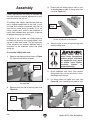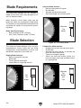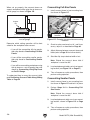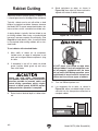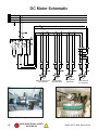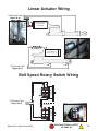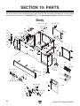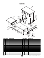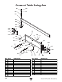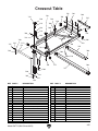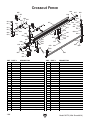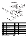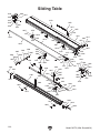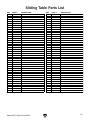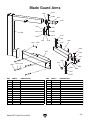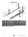
1
MODEL G0772 14" SLIDING TABLE SAW OWNER'S MANUAL (For models manufactured since 09/14) COPYRIGHT © MAY, 2015 BY GRIZZLY INDUSTRIAL, INC. WARNING: NO PORTION OF THIS MANUAL MAY BE REPRODUCED IN ANY SHAPE OR FORM WITHOUT THE WRITTEN APPROVAL OF GRIZZLY INDUSTRIAL, INC. #BBBLMNWK17287 PRINTED IN TAIWAN V1.05.15 This manual provides critical safety instructions on the proper setup, operation, maintenance, and service of this machine/tool. Save this document, refer to it often, and use it to instruct other operators. Failure to read, understand and follow the instructions in this manual may result in fire or serious personal injury—including amputation, electrocution, or death. The owner of this machine/tool is solely responsible for its safe use. This responsibility includes but is not limited to proper installation in a safe environment, personnel training and usage authorization, proper inspection and maintenance, manual availability and comprehension, application of safety devices, cutting/sanding/grinding tool integrity, and the usage of personal protective equipment. The manufacturer will not be held liable for injury or property damage from negligence, improper training, machine modifications or misuse. Some dust created by power sanding, sawing, grinding, drilling, and other construction activities contains chemicals known to the State of California to cause cancer, birth defects or other reproductive harm. Some examples of these chemicals are: • • • Lead from lead-based paints. Crystalline silica from bricks, cement and other masonry products. Arsenic and chromium from chemically-treated lumber. Your risk from these exposures varies, depending on how often you do this type of work. To reduce your exposure to these chemicals: Work in a well ventilated area, and work with approved safety equipment, such as those dust masks that are specially designed to filter out microscopic particles. Table of Contents INTRODUCTION................................................ 2 Contact Info.................................................... 2 Manual Accuracy............................................ 2 Identification.................................................... 3 Controls & Components.................................. 4 Glossary Of Terms.......................................... 7 Sliding Table Saw Capacities......................... 8 Machine Data Sheet....................................... 9 SECTION 1: SAFETY...................................... 12 Safety Instructions for Machinery................. 12 Additional Safety for Sliding Table Saws...... 14 Preventing Kickback..................................... 15 Protecting Yourself From Kickback.............. 15 SECTION 2: POWER SUPPLY....................... 16 440V Conversion.......................................... 18 SECTION 3: SETUP........................................ 19 Needed for Setup.......................................... 19 Unpacking..................................................... 19 Hardware Recognition Chart........................ 20 Inventory....................................................... 21 Cleanup......................................................... 23 Site Considerations....................................... 24 Lifting & Placing Saw.................................... 25 Assembly...................................................... 26 Dust Collection.............................................. 36 Power Connection........................................ 37 Test Run....................................................... 38 Recommended Adjustments......................... 40 SECTION 4: OPERATIONS............................ 41 Operation Overview...................................... 41 Workpiece Inspection................................... 42 Through & Non-Through Cuts...................... 42 Blade Guard.................................................. 43 Riving Knife................................................... 44 Blade Requirements..................................... 46 Blade Selection............................................. 46 Changing Blade Angle.................................. 47 Changing Blade Height................................. 48 Changing Blade Speed................................. 48 Changing Main Blade................................... 49 Replacing & Aligning Scoring Blade............. 51 Setting Up Crosscut Fence........................... 53 Rip Cutting.................................................... 55 Crosscutting.................................................. 57 Miter Cutting................................................. 59 Dado Cutting................................................. 61 Rabbet Cutting.............................................. 62 Resawing...................................................... 63 SECTION 5: SHOP MADE SAFETY ACCESSORIES............................................... 65 Featherboards............................................... 65 Push Sticks................................................... 68 Push Blocks.................................................. 69 Narrow-Rip Auxiliary Fence & Push Block... 70 SECTION 6: AFTERMARKET ACCESSORIES FROM GRIZZLY................... 72 SECTION 7: MAINTENANCE.......................... 75 Schedule....................................................... 75 Cleaning & Protecting................................... 75 Lubrication.................................................... 76 SECTION 8: SERVICE.................................... 77 Troubleshooting............................................ 77 Belt Service................................................... 79 Blade Tilt Calibration..................................... 80 Sliding Table Parallel Adjustment................. 82 Calibrating Rip Fence................................... 83 Squaring Crosscut Fence to Blade............... 84 SECTION 9: WIRING....................................... 86 Wiring Safety Instructions............................. 86 Electrical Overview....................................... 87 Relay Logic Diagram.................................... 88 Control Panel Wiring..................................... 89 220V Electrical Panel Schematic.................. 90 Main Motor Wiring......................................... 92 Scoring Motor Wiring .................................. 93 DC Motor Schematic .................................. 94 Linear Actuator Wiring ................................ 95 Belt Speed Rotary Switch Wiring.................. 95 SECTION 10: PARTS...................................... 96 Body.............................................................. 96 Tables........................................................... 98 Blade Enclosure............................................ 99 Main Blade Motor & Arbor.......................... 101 Blade Tilt System........................................ 103 Scoring Blade Motor & Arbor...................... 104 Crosscut Table Swing Arm......................... 106 Crosscut Table............................................ 107 Crosscut Fence........................................... 108 Rip Fence................................................... 109 Sliding Table............................................... 110 Blade Guard................................................ 112 Blade Guard Arms...................................... 113 Miter Fence................................................. 114 Electrical Panel........................................... 115 Labels & Cosmetics.................................... 116 Accessories................................................. 117 WARRANTY & RETURNS............................ 121 INTRODUCTION Contact Info Manual Accuracy We stand behind our machines! If you have questions or need help, contact us with the information below. Before contacting, make sure you get the serial number and manufacture date from the machine ID label. This will help us help you faster. We are proud to provide a high-quality owner’s manual with your new machine! Grizzly Technical Support 1203 Lycoming Mall Circle Muncy, PA 17756 Phone: (570) 546-9663 Email: [email protected] We want your feedback on this manual. What did you like about it? Where could it be improved? Please take a few minutes to give us feedback. Grizzly Documentation Manager P.O. Box 2069 Bellingham, WA 98227-2069 Email: [email protected] We made every effort to be exact with the instructions, specifications, drawings, and photographs in this manual. Sometimes we make mistakes, but our policy of continuous improvement also means that sometimes the machine you receive is slightly different than shown in the manual. If you find this to be the case, and the difference between the manual and machine leaves you confused or unsure about something, check our website for an updated version. We post current manuals and manual updates for free on our website at www.grizzly.com. Alternatively, you can call our Technical Support for help. Before calling, make sure you write down the Manufacture Date and Serial Number from the machine ID label (see below). This information is required for us to provide proper tech support, and it helps us determine if updated documentation is available for your machine. Manufacture Date Serial Number -2- Model G0772 (Mfd. Since 09/14) Identification Become familiar with the names and locations of the controls and components shown below to better understand the instructions in this manual. B C E D F G A H I A. Crosscut Table. Provides a wide, stable platform for supporting full-size panels during crosscutting operations. B. Crosscut Fence. Used during crosscutting operations to keep panels at 90˚ angle to blade. Features a scale and flip stops. C. Flip Stops. Used for quick, precise measurements for repeatable cuts when using crosscutting fence. D. Blade Guard. Fully-enclosed, adjustable blade guard maintains maximum protection around saw blade with a 3" dust port that effectively extracts dust from cutting operation. F. Rip Fence. Fully-adjustable with micro-adjust knob for precision cuts. Fence face can be positioned for standard cutting operations, or placed in lower position for blade guard clearance during narrow ripping operations. G. Sliding Table Lever. Allows sliding table to be locked in stationary position. Push down to release; pull up to lock. H. Sliding Table. Ball-bearing rollers make it quick and easy to guide large, heavy panels through cut. I. Control Panel. Features push-button controls for operating saw. E. Miter Fence. Allows precise miter cuts from 30˚left to 45˚ right. Model G0772 (Mfd. Since 09/14) -3- Controls & Components D. Rip Fence Rail. Provides a stable sideto-side path for sliding rip fence assembly toward or away from blade. E. Rip Fence Lock Handle. Secures rip fence assembly in position along fence rail so workpiece is stable when cutting. To reduce your risk of serious injury, read this entire manual BEFORE using machine. F. Micro-Adjust Lock Knob. Enables use of micro-adjust knob for precise positioning of rip fence. Miter Fence Refer to Figures 1–6 and the following descriptions to become familiar with the basic controls and components of this machine. Understanding these items and how they work will help you understand the rest of the manual and stay safe when operating this saw. G I L J K H Rip Fence B A Figure 2. Miter fence controls. C D F E G. Flip Stop. Used for quick, precise measurements for repeatable cuts when using miter fence. H. Clamp Plate Ratcheting Handle. Locks miter fence in position once desired angle is determined. Figure 1. Rip fence controls. I. Lock Knobs. Secure position of aluminum slide bar in miter fence. A. Rip Fence Scale. Helps measure cut during ripping operations. Features a dual-calibration block to ensure scale is easy to read whether fence is in high or low position. J. Pivot Knob. Secures miter fence to sliding table T-slot. B. Slide Lock Handle. Secures aluminum fence face on its forward/backward slide track. C. Micro-Adjust Knob. Provides precise adjustment of fence. Loosen micro-adjust lock knob to use this feature. -4- K. Miter Fence Scale. Helps measure angle of cut during miter operations. Features resolution of 1⁄ 2˚. L. Aluminum Slide Bar: Adjusts to extend or shorten length of miter fence. Model G0772 (Mfd. Since 09/14) Control Panel M N O AE AD AC P AB Q AA Z Y R X S W T U V Figure 3. Control panel functions. M.Keypad. For entering desired angle of saw blades. N. Blade Angle Display. Displays current angle of saw blades. O. Main Blade Up Key. Increases height of main saw blade. P. Scoring Blade Left Key. Moves scoring blade left to align with main blade. Q. Arbor RPM Display. Displays current RPM of saw blade. R. Scoring Blade Up Key. Increases height of scoring blade. S. Main Blade ON Button. Enables power to main blade. T. Scoring Blade ON Button. Enables power to scoring blade. U. Emergency Stop Button. Turns both motors OFF and disables control panel. To reset, twist clockwise until button pops out. Model G0772 (Mfd. Since 09/14) V. Motor OFF Button. Turns both motors OFF. W. Scoring Blade Down Key. Decreases height of scoring blade. X. Scoring Blade Right Key. Moves scoring blade right to align with main blade. Y. Main Blade Down Key. Decreases height of main saw blade. Z. "+" Key. Manually increases angle of saw blades in increments of 0.1". AA.Start Key. Starts trunnion movement after an angle has been entered. AB.Stop Key. Stops trunnion movement. AC."-" Key. Manually decreases angle of saw blades in increments of 0.1". AD.Set Key. Sets blade angles entered into keypad. Also used for calibration. AE."C" Key. Clears typed entries in display. -5- Saw Blades AF Blade Guard AG AH AI Figure 5. Blade guard components. Figure 4. Saw blades. AF.Riving Knife. Maintains kerf opening during cutting operations. This function is crucial to preventing kickback caused by kerf closing behind blade. AI. Lock Knob. When loosened, allows blade guard support arm to swing out of the way. Master Power AG.Main Blade. Performs cutting operation. AH.Scoring Blade. Rotates in opposite direction of main blade and pre-cuts surface of workpiece before actual cutting operation is performed to reduce tearout or chipping. Scoring blade is adjustable for kerf thickness and alignment with main blade. AJ Figure 6. Location of master power switch. AJ. Master Power Switch. Enables power flow to machine. -6- Model G0772 (Mfd. Since 09/14) Glossary Of Terms The following is a list of common definitions, terms and phrases used throughout this manual as they relate to this sliding table saw and woodworking in general. Become familiar with these terms for assembling, adjusting or operating this machine. Your safety is VERY important to us at Grizzly! Arbor: Metal shaft extending from the drive mechanism, to which saw blade is mounted. Bevel Edge Cut: Tilting the arbor and saw blade to an angle between 0° and 45° to cut a beveled edge onto a workpiece. Blade Guard: Metal or plastic safety device that mounts over the saw blade. Its function is to prevent the operator from coming into contact with the saw blade. Crosscut: Cutting operation in which the crosscut fence is used to cut across the grain, or across the shortest width of the workpiece. Dado Blade: Blade or set of blades that are used to cut grooves and rabbets. Dado Cut: Cutting operation that cuts a flat bottomed groove into the face of the workpiece. Featherboard: Safety device used to keep the workpiece against the rip fence and against the table surface. Kerf: The resulting cut or gap in the workpiece from the saw blade passing through it while cutting. Kickback: A dangerous event that happens if the blade catches on the workpieces while cutting. The force of the blade then throws the workpiece back toward the operator with what sounds like a horrible explosion. The danger comes from flying stock striking the operator or bystanders. The operator’s hands may also be pulled into the blade during the kickback. Refer to Preventing Kickback on Page 15 for additional information. Model G0772 (Mfd. Since 09/14) Non-Through Cut: A sawing operation in which the workpiece is not completely sawn through. Dado and rabbet cuts are considered NonThrough Cuts because the blade does not protrude above the top face of the wood stock. Parallel: When two objects are spaced an equal distance apart at every point along two given lines or planes (I.e. the rip fence face is parallel to the face of the saw blade). Perpendicular: Lines or planes that intersect and form right angles. I.e. the blade is perpendicular to the table surface. Push Stick: Safety device used to push the workpiece through a cutting operation. Used most often when rip cutting thin workpieces. Rabbet: Cutting operation that creates an L-shaped channel along the edge of the workpiece. Rip Cut: Cutting operation in which the rip fence is used to cut with the grain, or cut across the widest width of the workpiece. Riving Knife: Metal plate located behind the blade maintains the kerf opening in the wood when cutting, and helps reduce the risk of injury from a kickback that otherwise would result in amputation. Straightedge: A tool with a perfectly straight edge used to check the flatness, parallelism, or consistency of a surface(s). Through Cut: A sawing operation in which the workpiece is completely sawn through. -7- SLIDING TABLE SAW CAPACITIES Customer Service #: (570) 546-9663 • To Order Call: (800) 523-4777 • Fax #: (800) 438-5901 MODEL G0772 14" SLIDING TABLE SAW 126" 126" Ripping Width Cross Cut 521/2" 126" 61" 25" 96" Miter Cut 90º (push cut) Miter Cut 45º (push cut) 83" 83" 88" Cross Cut (fence not extended) 471/4" Miter Cut 45º 126" 66" 651/4" 96" (NO CAPACITY) 451/2" Miter Cut 45º (push cut, fence not extended) -8- Miter Cut 45º (fence not extended) Model G0772 (Mfd. Since 09/14) MACHINE DATA SHEET Customer Service #: (570) 546-9663 · To Order Call: (800) 523-4777 · Fax #: (800) 438-5901 MODEL G0772 14" SLIDING TABLE SAW Product Dimensions: Weight............................................................................................................................................................ 2486 lbs. Width (side-to-side) x Depth (front-to-back) x Height....................................................................... 132 x 130 x 55 in. Footprint (Length x Width)..................................................................................................................... 64-1/2 x 39 in. Space Required for Full Range of Movement (Width x Depth)................................................................ 276 x 195 in. Shipping Dimensions: Carton #1 Type................................................................................................................................................ Wood Crate Content................................................................................................................................................. Machine Weight.................................................................................................................................................. 2389 lbs. Length x Width x Height............................................................................................................. 90 x 52 x 44 in. Must Ship Upright......................................................................................................................................... Yes Carton #2 Type................................................................................................................................................ Wood Crate Content.......................................................................................................................................... Sliding Table Weight.................................................................................................................................................... 543 lbs. Length x Width x Height........................................................................................................... 132 x 19 x 14 in. Must Ship Upright......................................................................................................................................... Yes Electrical: Power Requirement..................................................................................................... 220V or 440V, 3-Phase, 60 Hz Prewired Voltage.................................................................................................................................................. 220V Full-Load Current Rating..................................................................................................... 28A at 220V, 14A at 440V Minimum Circuit Size.......................................................................................................... 40A at 220V, 20A at 440V Connection Type........................................................................................... Permanent (Hardwire to Shutoff Switch) Switch Type............................................................................................ Control Panel w/Magnetic Switch Protection Motors: Main Type........................................................................................................................................... TEFC Induction Horsepower.............................................................................................................................................. 10 HP Phase.................................................................................................................................................... 3-Phase Amps.................................................................................................................................................. 25A/12.5A Speed................................................................................................................................................ 3450 RPM Power Transfer .................................................................................................................................. Belt Drive Bearings..................................................................................................... Shielded & Permanently Lubricated Scoring Blade Type........................................................................................................................................... TEFC Induction Horsepower................................................................................................................................................ 1 HP Phase.................................................................................................................................................... 3-Phase Amps...................................................................................................................................................... 3A/1.5A Speed................................................................................................................................................ 3450 RPM Power Transfer ........................................................................................................................... Flat-Belt Drive Bearings........................................................................................................... Shielded & Permanently Sealed Model G0772 The information contained herein is deemed accurate as of 5/7/2015 and represents our most recent product specifications. Due to our ongoing improvement efforts, this information may not accurately describe items previously purchased. Model G0772 (Mfd. Since 09/14) PAGE 1 OF 3 -9- Main Specifications: Operation Information Main Blade Size......................................................................................................................................... 14 in. Riving Knife/Spreader Thickness.......................................................................................................... 0.098 in. Required Blade Body Thickness........................................................................................................... 0.108 in. Required Blade Kerf Thickness............................................................................................................ 0.108 in. Main Blade Arbor Size................................................................................................................................. 1 in. Scoring Blade Size................................................................................................................. 120mm (4-3/4 in.) Scoring Blade Arbor Size........................................................................................................................ 22 mm Main Blade Tilt.................................................................................................................................. 0 – 45 deg. Main Blade Speed............................................................................................... 3000, 4000, 5000, 6000 RPM Scoring Blade Tilt............................................................................................................................. 0 – 45 deg. Scoring Blade Speed......................................................................................................................... 8000 RPM Cutting Capacities Max Depth of Cut At 90 Deg........................................................................................................................ 4 in. Max Depth of Cut At 45 Deg.................................................................................................................. 2-3/4 in. Max Dist From Blade To Column............................................................................................................... 60 in. Rip Fence Max Cut Width.................................................................................................................... 52-1/2 in. Sliding Table w/Crosscut Fence Max Cut Width...................................................................................... 126 in. Sliding Table w/Crosscut Fence Max Cut Length.................................................................................... 126 in. Miter Fence Max Cut Width at 45 Deg....................................................................................................... 97 in. Table Information Floor To Table Height................................................................................................................................ 35 in. Table Size Length................................................................................................................................ 39-1/4 in. Table Size Width................................................................................................................................. 34-1/2 in. Table Size Thickness................................................................................................................................... 3 in. Table Size With Ext Wings Length............................................................................................................ 60 in. Table Size With Ext Wings Width........................................................................................................ 59-1/4 in. Table Size With Ext Wings Thickness......................................................................................................... 3 in. Sliding Table Length................................................................................................................................ 126 in. Sliding Table Width.................................................................................................................................... 15 in. Sliding Table Thickness......................................................................................................................... 8-5/8 in. Sliding Table T-Slot Top Width................................................................................................................. 7/8 in. Sliding Table T-Slot Height....................................................................................................................... 3/4 in. Sliding Table T-Slot Bottom Width............................................................................................................ 7/8 in. Fence Information Crosscut Fence Type........................................................................... Extruded Aluminum w/Telescoping End Crosscut Fence Size Length...................................................................................................................... 70 in. Crosscut Fence Size Max Extended Length..................................................................................... 126-1/2 in. Crosscut Fence Size Width................................................................................................................... 3-1/4 in. Crosscut Fence Size Height.................................................................................................................. 2-3/4 in. Crosscut Fence Number of Stops.................................................................................................................... 2 Rip Fence Type............................................................... 2-Position Single-Lever Locking w/Micro Adjustment Rip Fence Size Length........................................................................................................................ 47-1/4 in. Rip Fence Size Width.................................................................................................................................. 2 in. Rip Fence Size Height........................................................................................................................... 3-5/8 in. Miter Fence Type............................................................................................. T-Slot Mounted Aluminum Tube Miter Fence Size Length...................................................................................................................... 47-1/4 in. Miter Fence Size Max Extended Length.................................................................................................... 83 in. Miter Fence Size Width......................................................................................................................... 3-1/8 in. Miter Fence Size Height........................................................................................................................ 1-1/2 in. Miter Fence Number of Stops........................................................................................................................... 1 -10- G0772 Model The information contained herein is deemed accurate as of 5/7/2015 and represents our most recent product specifications. Model G0772 (Mfd. SincePAGE 09/14) 2 OF 3 Due to our ongoing improvement efforts, this information may not accurately describe items previously purchased. Construction Materials Table.................................................................................................................................................... Cast Iron Sliding Table....................................................................................................................................... Aluminum Extension Table.......................................................................................................................................... Steel Cabinet....................................................................................................................................................... Steel Rip Fence........................................................................................................................................... Aluminum Miter Fence......................................................................................................................................... Aluminum Rip Fence Rails.......................................................................................................................... Chromed Steel Guard....................................................................................................................................................... Plastic Spindle Bearing Type.................................................................................... Sealed & Permanently Lubricated Cabinet Paint Type/Finish.................................................................................................................... Urethane Other Related Information No of Dust Ports............................................................................................................................................... 2 Dust Port Size.......................................................................................................................................... 3, 5 in. Other Specifications: Country of Origin .............................................................................................................................................. Taiwan Warranty ........................................................................................................................................................... 1 Year Approximate Assembly & Setup Time ............................................................................................................. 5 Hours Serial Number Location .................................................................... ID Label on Right Side of Electrical Control Box ISO 9001 Factory .................................................................................................................................................... No CSA, ETL, or UL Certified/Listed ............................................................................................................................ No Features: Cross-Slide Table with Eccentric Locking Clamp and Hard Chrome-Plated Slide-Way Easily Adjustable Saw Guard with Built-In Dust Hood Miter Fence Adjustable 30 Degrees Left and 45 Degrees Right Push-Button Digital Control of Blade Speed, Height Adjustments, Blade Tilt, and Scoring Blade Alignment Scoring Blade Virtually Eliminates Tear-Out Sliding Table on Vertical Guide System with Precision Bearing Rollers Accepts 12" and 14" Blades information contained herein is deemed accurate as of 5/7/2015 and represents our most recent product specifications. Model G0772The (Mfd. Since 09/14) Model G0772 Due to our ongoing improvement efforts, this information may not accurately describe items previously purchased. PAGE-113 OF 3 SECTION 1: SAFETY For Your Own Safety, Read Instruction Manual Before Operating This Machine The purpose of safety symbols is to attract your attention to possible hazardous conditions. This manual uses a series of symbols and signal words intended to convey the level of importance of the safety messages. The progression of symbols is described below. Remember that safety messages by themselves do not eliminate danger and are not a substitute for proper accident prevention measures. Always use common sense and good judgment. Indicates an imminently hazardous situation which, if not avoided, WILL result in death or serious injury. Indicates a potentially hazardous situation which, if not avoided, COULD result in death or serious injury. Indicates a potentially hazardous situation which, if not avoided, MAY result in minor or moderate injury. It may also be used to alert against unsafe practices. NOTICE This symbol is used to alert the user to useful information about proper operation of the machine. Safety Instructions for Machinery OWNER’S MANUAL. Read and understand this owner’s manual BEFORE using machine. TRAINED OPERATORS ONLY. Untrained operators have a higher risk of being hurt or killed. Only allow trained/supervised people to use this machine. When machine is not being used, disconnect power, remove switch keys, or lock-out machine to prevent unauthorized use—especially around children. Make workshop kid proof! DANGEROUS ENVIRONMENTS. Do not use machinery in areas that are wet, cluttered, or have poor lighting. Operating machinery in these areas greatly increases the risk of accidents and injury. MENTAL ALERTNESS REQUIRED. Full mental alertness is required for safe operation of machinery. Never operate under the influence of drugs or alcohol, when tired, or when distracted. -12- ELECTRICAL EQUIPMENT INJURY RISKS. You can be shocked, burned, or killed by touching live electrical components or improperly grounded machinery. To reduce this risk, only allow qualified service personnel to do electrical installation or repair work, and always disconnect power before accessing or exposing electrical equipment. DISCONNECT POWER FIRST. Always disconnect machine from power supply BEFORE making adjustments, changing tooling, or servicing machine. This prevents an injury risk from unintended startup or contact with live electrical components. EYE PROTECTION. Always wear ANSI-approved safety glasses or a face shield when operating or observing machinery to reduce the risk of eye injury or blindness from flying particles. Everyday eyeglasses are NOT approved safety glasses. Model G0772 (Mfd. Since 09/14) WEARING PROPER APPAREL. Do not wear clothing, apparel or jewelry that can become entangled in moving parts. Always tie back or cover long hair. Wear non-slip footwear to reduce risk of slipping and losing control or accidentally contacting cutting tool or moving parts. HAZARDOUS DUST. Dust created by machinery operations may cause cancer, birth defects, or long-term respiratory damage. Be aware of dust hazards associated with each workpiece material. Always wear a NIOSH-approved respirator to reduce your risk. HEARING PROTECTION. Always wear hearing protection when operating or observing loud machinery. Extended exposure to this noise without hearing protection can cause permanent hearing loss. REMOVE ADJUSTING TOOLS. Tools left on machinery can become dangerous projectiles upon startup. Never leave chuck keys, wrenches, or any other tools on machine. Always verify removal before starting! USE CORRECT TOOL FOR THE JOB. Only use this tool for its intended purpose—do not force it or an attachment to do a job for which it was not designed. Never make unapproved modifications—modifying tool or using it differently than intended may result in malfunction or mechanical failure that can lead to personal injury or death! AWKWARD POSITIONS. Keep proper footing and balance at all times when operating machine. Do not overreach! Avoid awkward hand positions that make workpiece control difficult or increase the risk of accidental injury. CHILDREN & BYSTANDERS. Keep children and bystanders at a safe distance from the work area. Stop using machine if they become a distraction. GUARDS & COVERS. Guards and covers reduce accidental contact with moving parts or flying debris. Make sure they are properly installed, undamaged, and working correctly BEFORE operating machine. Model G0772 (Mfd. Since 09/14) FORCING MACHINERY. Do not force machine. It will do the job safer and better at the rate for which it was designed. NEVER STAND ON MACHINE. Serious injury may occur if machine is tipped or if the cutting tool is unintentionally contacted. STABLE MACHINE. Unexpected movement during operation greatly increases risk of injury or loss of control. Before starting, verify machine is stable and mobile base (if used) is locked. USE RECOMMENDED ACCESSORIES. Consult this owner’s manual or the manufacturer for recommended accessories. Using improper accessories will increase the risk of serious injury. UNATTENDED OPERATION. To reduce the risk of accidental injury, turn machine OFF and ensure all moving parts completely stop before walking away. Never leave machine running while unattended. MAINTAIN WITH CARE. Follow all maintenance instructions and lubrication schedules to keep machine in good working condition. A machine that is improperly maintained could malfunction, leading to serious personal injury or death. DAMAGED PARTS. Regularly inspect machine for damaged, loose, or mis-adjusted parts—or any condition that could affect safe operation. Immediately repair/replace BEFORE operating machine. For your own safety, DO NOT operate machine with damaged parts! MAINTAIN POWER CORDS. When disconnecting cord-connected machines from power, grab and pull the plug—NOT the cord. Pulling the cord may damage the wires inside. Do not handle cord/plug with wet hands. Avoid cord damage by keeping it away from heated surfaces, high traffic areas, harsh chemicals, and wet/damp locations. EXPERIENCING DIFFICULTIES. If at any time you experience difficulties performing the intended operation, stop using the machine! Contact our Technical Support at (570) 546-9663. -13- Additional Safety for Sliding Table Saws Serious injury or death can occur from getting cut or having body parts, such as fingers, amputated by rotating saw blade. Workpieces thrown by kickback can strike operators or bystanders with deadly force. Flying particles from cutting operations or broken blades can cause eye injuries or blindness. To minimize risk of getting hurt or killed, anyone operating machine MUST completely heed hazards and warnings below. HAND & BODY POSITIONING. Keep hands away from saw blade and out of blade path during operation, so they cannot slip accidentally into blade. Stand to side of blade path. Never reach around, behind, or over blade. Only operate at front of machine. BLADE GUARD. Use blade guard for all cuts that allow it to be used safely. Make sure blade guard is installed and adjusted correctly. Promptly repair or replace if damaged. Re-install blade guard immediately after operations that require its removal. FENCE ADJUSTMENTS. Make sure rip fence remains properly adjusted and parallel with blade. Always lock fence before using. PUSH STICKS/BLOCKS. Use push sticks or push blocks whenever possible to keep your hands farther away from blade while cutting. In event of an accident these devices will often take damage that would have happened to hands/ fingers. RIVING KNIFE. Use riving knife for all cuts. Make sure riving knife is aligned and positioned correctly. Promptly repair or replace it if damaged. BLADE ADJUSTMENTS. Adjusting blade height or tilt during operation increases risk of crashing blade and sending metal fragments flying with deadly force at operator or bystanders. Only adjust blade height and tilt when blade is completely stopped and saw is OFF. KICKBACK. Kickback occurs when saw blade ejects workpiece back toward operator. Know how to reduce risk of kickback. Learn how to protect yourself if it does occur. CHANGING BLADES. Always disconnect power before changing blades. Changing blades while saw is connected to power greatly increases injury risk if saw is accidentally powered up. WORKPIECE CONTROL. Feeding workpiece incorrectly increases risk of kickback. Make sure workpiece is in stable position on tables and supported by rip fence or crosscut fence during cutting operation. Never start saw with workpiece touching blade. Allow blade to reach full speed before cutting. Only feed workpiece against direction of main blade rotation. Always use some type of guide to feed workpiece in a straight line. Never back workpiece out of cut or move it backwards or sideways after starting a cut. Feed cuts all the way through to completion. Never perform any operation “freehand”. Turn OFF saw and wait until blade is completely stopped before removing workpiece. DAMAGED SAW BLADES. Never use blades that have been dropped or otherwise damaged. -14- CUTTING CORRECT MATERIAL. Never cut materials not intended for this saw. Only cut natural and man-made wood products, laminate covered wood products, and some plastics. Cutting metal, glass, stone, tile, etc. increases risk of operator injury due to kickback or flying particles. Model G0772 (Mfd. Since 09/14) Preventing Kickback Protecting Yourself From Kickback Do the following to prevent kickback: • When rip cutting, only cut workpieces that have at least one smooth and straight edge. DO NOT cut excessively warped, cupped or twisted wood. If workpiece warpage is questionable, always choose another workpiece. • Never attempt freehand cuts. If the workpiece is not fed parallel with the blade, kickback will likely occur. Always use the rip fence or crosscut fence to support the workpiece. • Ensure sliding table slides parallel with the blade; otherwise, the chances of kickback are extreme. Take the time to check and adjust the sliding table before cutting. • Always use the riving knife whenever possible. It reduces risk of kickback and reduces your risk of injury if it does occur. • Always keep blade guard installed and in good working order. • Feed cuts through to completion. Any time you stop feeding a workpiece in the middle of a cut, the chance of kickback is greatly increased. • Ensure rip fence is adjusted parallel with the blade; otherwise, the chances of kickback are extreme. Take the time to check and adjust the rip fence before cutting. Even if you know how to prevent kickback, it may still happen. Here are some precautions to help protect yourself if kickback DOES occur: • Stand to the side of the blade path when cutting. If a kickback does occur, the thrown workpiece usually travels directly towards the front of the blade. • Wear safety glasses or a face shield. In the event of a kickback, your eyes and face are the most vulnerable parts of your body. • Never, for any reason, place your hand behind the blade path. Should kickback occur, your hand will be pulled into the blade. • Use a push stick or push block to keep your hands farther away from the moving blade. If a kickback occurs, these safety devices will most likely take the damage that your hand would have received. • Use featherboards or anti-kickback devices to prevent or slow down kickback. Statistics show that the most common accidents among table saw users can be linked to kickback. Kickback is typically defined as the high-speed expulsion of stock from the table saw toward the operator. In addition to the danger of the operator or others in the area being struck by the flying stock, it is often the case that the operator’s hands are pulled into the blade during the kickback. Model G0772 (Mfd. Since 09/14) -15- SECTION 2: POWER SUPPLY Availability Circuit Information Before installing the machine, consider the availability and proximity of the required power supply circuit. If an existing circuit does not meet the requirements for this machine, a new circuit must be installed. To minimize the risk of electrocution, fire, or equipment damage, installation work and electrical wiring must be done by an electrician or qualified service personnel in accordance with all applicable codes and standards. A power supply circuit includes all electrical equipment between the breaker box or fuse panel in the building and the machine. The power supply circuit used for this machine must be sized to safely handle the full-load current drawn from the machine for an extended period of time. (If this machine is connected to a circuit protected by fuses, use a time delay fuse marked D.) Electrocution, fire, or equipment damage may occur if machine is not correctly grounded and connected to the power supply. Full-Load Current Rating The full-load current rating is the amperage a machine draws at 100% of the rated output power. On machines with multiple motors, this is the amperage drawn by the largest motor or sum of all motors and electrical devices that might operate at one time during normal operations. Full-Load Current Rating at 220V...... 28 Amps Full-Load Current Rating at 440V...... 14 Amps The full-load current is not the maximum amount of amps that the machine will draw. If the machine is overloaded, it will draw additional amps beyond the full-load rating. If the machine is overloaded for a sufficient length of time, damage, overheating, or fire may result— especially if connected to an undersized circuit. To reduce the risk of these hazards, avoid overloading the machine during operation and make sure it is connected to a power supply circuit that meets the specified circuit requirements. -16- For your own safety and protection of property, consult an electrician if you are unsure about wiring practices or electrical codes in your area. Note: Circuit requirements in this manual apply to a dedicated circuit—where only one machine will be running on the circuit at a time. If machine will be connected to a shared circuit where multiple machines may be running at the same time, consult an electrician or qualified service personnel to ensure circuit is properly sized for safe operation. Circuit Requirements for 220V This machine is prewired to operate on a power supply circuit that has a verified ground and meets the following requirements: Nominal Voltage.................... 220V, 230V, 240V Cycle...........................................................60 Hz Phase..................................................... 3-Phase Power Supply Circuit.......................... 40 Amps Circuit Requirements for 440V This machine can be converted to operate on a power supply circuit that has a verified ground and meets the requirements listed below. (Refer to Voltage Conversion instructions for details.) Nominal Voltage.............................. 440V, 480V Cycle...........................................................60 Hz Phase..................................................... 3-Phase Power Supply Circuit.......................... 20 Amps Model G0772 (Mfd. Since 09/14) Connection Type Phase Converters A permanently connected (hardwired) power supply is typically installed with wires running through mounted and secured conduit. A disconnecting means, such as a locking switch (see following figure), must be provided to allow the machine to be disconnected (isolated) from the power supply when required. This installation must be performed by an electrician in accordance with all applicable electrical codes and ordinances. Avoid using a static phase converter to supply 3-Phase power for this machine, as it could damage or decrease the life of sensitive electrical components. If you must use a phase converter, only use a rotary phase converter that is sized at least 50% larger than the largest HP rating of this machine. If using a phase converter to supply power, only connect the manufactured leg or "wild wire" to the "S" terminal (see location on Page 87). The S terminal can handle power fluctuations because it is wired directly to the motor. Power Source Locking Disconnect Switch Conduit Machine Conduit Ground Ground Figure 7. Typical setup of a permanently connected machine. Grounding Instructions In the event of a malfunction or breakdown, grounding provides a path of least resistance for electrical current to reduce the risk of electric shock. A permanently connected machine must be connected to a grounded metal permanent wiring system; or to a system having an equipmentgrounding conductor. All grounds must be verified and rated for the electrical requirements of the machine. Improper grounding can increase the risk of electric shock! Serious injury could occur if you connect the machine to power before completing the setup process. DO NOT connect to power until instructed later in this manual. Extension Cords Since this machine must be permanently connected to the power supply, an extension cord cannot be used. Model G0772 (Mfd. Since 09/14) -17- 440V Conversion The Model G0772 can be converted for 440V operation using the optional Part# P07721412. This can be purchased by contacting the Grizzly Order Desk at (800) 523-4777. This conversion job consists of: 1) replacing the overload relays and 2) rewiring the main and scoring blade motors for 440V operation. 3. Remove main motor overload relay for 220V. Replace with RHU-10/7.5K1 overload relay included with 440V Conversion Kit. Set overload dial to 6.5A (see Figure 9). 4. Remove scoring motor overload relay for 220V. Replace with RHU-10/2K1 overload relay included with 440V Conversion Kit. Set amperage dial to 1.6A (see Figure 9). All wiring changes must be done by an electrician or qualified service personnel before the saw is connected to the power source. If, at any time during this procedure you need help, call Grizzly Tech Support at (570) 546-9663. Before performing the conversion procedure, we recommend setting the blade to 0° and raising it all the way up to create clearance under the main and scoring motor junction boxes for rewiring. RHU-10/7.5K1 (Set to 6.5A) RHU-10/2K1 (Set to 1.6A) To convert G0772 for 440V operation: 1. DISCONNECT MACHINE FROM POWER! 2. Open electrical panel door (see Figure 8). Figure 9. Overload relays from 440V Conversion Kit installed and set for specified trip current. 5. Close electrical panel door. 6. Open motor cabinet door on back of saw. Electrical Panel Door 7. Rewire main blade and scoring blade motors to 440V. Refer to wiring diagrams on Pages 93–92. 8. Close motor cabinet door. Figure 8. Location of electrical panel door. -18- Model G0772 (Mfd. Since 09/14) SECTION 3: SETUP Needed for Setup This machine presents serious injury hazards to untrained users. Read through this entire manual to become familiar with the controls and operations before starting the machine! Wear safety glasses during the entire setup process! HEAVY LIFT! Straining or crushing injury may occur from improperly lifting machine or some of its parts. To reduce this risk, get help from other people and use a forklift (or other lifting equipment) rated for weight of this machine. The following items are needed, but not included, for the setup/assembly of this machine. DescriptionQty • Additional People........................................ 4 • Safety Glasses......................... 1 Per Person • Cleaner/Degreaser (Page 23)..... As Needed • Disposable Shop Rags................ As Needed • Forklift (Rated for at least 3000 lbs.)........... 1 • Straightedge 4'............................................ 1 • Level............................................................ 1 • Screwdriver Phillips #2................................ 1 • Open-End Wrenches 13mm, 19mm.......1 Ea • Dust Collection System w/5" Branch Line... 1 • Dust Hose & Hose Clamp 5"..................1 Ea • Dust Hose & Hose Clamp 3"..................1 Ea • Y-Fitting 3" x 5" x 5".................................... 1 • Feeler Gauge Set........................................ 1 Unpacking Your machine was carefully packaged for safe transportation. Remove the packaging materials from around your machine and inspect it. If you discover any damage, please call us immediately at (570) 546-9663 for advice. Save the containers and all packing materials for possible inspection by the carrier or its agent. Otherwise, filing a freight claim can be difficult. When you are completely satisfied with the condition of your shipment, inventory the contents. SUFFOCATION HAZARD! Keep children and pets away from plastic bags or packing materials shipped with this machine. Discard immediately. Model G0772 (Mfd. Since 09/14) -19- Hardware Recognition Chart -20- Model G0772 (Mfd. Since 09/14) Inventory A The following is a list of items shipped with your machine. Before beginning setup, lay these items out and inventory them. If any non-proprietary parts are missing (e.g. a nut or a washer), we will gladly replace them; or for the sake of expediency, replacements can be obtained at your local hardware store. Crate 1 (Figure 10) Qty A. Saw Base Unit............................................. 1 B. Small Extension Table................................. 1 C. Large Extension Table................................ 1 D. Crosscut Table Frame................................. 1 E. Large Extension Table Brace (L)................. 1 F. Large Extension Table Brace (R)................ 1 G. Rip Fence Rail w/Fasteners........................ 1 —Hex Nuts M20-2.5................................... 9 —Flat Washers 20mm................................ 6 H. Rip Fence Base Assembly.......................... 1 I. Crosscut Fence Flip Stops.......................... 2 J. End Plate (Sliding Table)............................. 1 K. End Handle (Sliding Table).......................... 1 L. Push Handle................................................ 1 M. Push Stick................................................... 1 N. Flat Blade Guard Assembly........................ 1 O. Bubble Blade Guard Assembly................... 1 P. Blade Guard Swing Arm.............................. 1 Q. Blade Guard Lower Support Arm................ 1 R. Blade Guard Upper Support Arm................ 1 NOTICE B C D E F G H I J K L M O N If you cannot find an item on this list, carefully check around/inside the machine and packaging materials. Often, these items get lost in packaging materials while unpacking or they are pre-installed at the factory. P Q R Figure 10. Crate 1 inventory. Model G0772 (Mfd. Since 09/14) -21- Crate 1 Continued (Figure 11) Qty S. Tool Box...................................................... 1 T. Grease Gun................................................. 1 U. Riving Knife................................................. 1 V.Open-End Wrench 30 x 41mm.................... 1 W. Scoring Blade Wrench................................ 1 X. Scoring Blade Shims................................... 4 Y. Tool Holder.................................................. 1 Z. Hex Wrench Set (1.5, 2, 2.5, 3, 4, 5, 5.5, 6, 8, 10mm) ....1 Ea AA. Open-End Wrench Set .............. (8/9, 10/12, 12/14, 14/17, 17/19, 21/23mm)..............1 Ea AB.Green Touch-Up Paint Can......................... 1 AC.Beige Touch-Up Paint Can.......................... 1 AD.Blade Locking Tool...................................... 1 AE.Base Feet.................................................... 4 AF. Foot Studs M14-2.0 x 45............................. 4 AG.Sliding Table Lever...................................... 1 AH.Cabinet Keys............................................... 2 Crate 2 (Figure 12) Qty AI. Crosscut Fence........................................... 1 AJ. Sliding Table................................................ 1 AK.Miter Fence................................................. 1 AL.Rip Fence.................................................... 1 AM.Short Support Bar....................................... 1 AN.Long Support Bar........................................ 1 AO.Rip Fence Table Scale Bracket . ................ 1 AP. End-Caps.................................................... 4 AI AJ AK AP AL AM T AN AO S Figure 12. Crate 2 inventory. U AD AC Hardware (not shown) Qty Blade Guard Lower Support Arm: —Hex Bolts M10-1.5 x 25............................ 4 —Lock Washers 10mm............................... 4 —Flat Washers 10mm................................. 4 V AE W AF AB AG AA AH X Z Figure 11. Crate 1 toolbox inventory. Y Blade Guard Upper Support Arm: —Hex Bolts M10-1.5 x 25............................ 2 —Lock Washers 10mm............................... 2 —Flat Washers 10mm................................. 2 Crosscut Fence: — Wood End-Cap....................................... 1 — Tap Screws #6 x 1"................................. 4 — Flat Washers 4mm.................................. 4 Rip Fence Table Scale Bracket: —Flat Hd. Screws M6-1 x 30...................... 2 —Flat Hd. Screws M6-1 x 35...................... 2 —Flat Washers 6mm.................................. 2 —Lock Washers 6mm................................. 2 —Hex Nuts M6-1......................................... 2 Saw Base: —Hex Bolts M16-2 x 70 w/Hex Nuts........... 4 -22- Model G0772 (Mfd. Since 09/14) Cleanup The unpainted surfaces of your machine are coated with a heavy-duty rust preventative that prevents corrosion during shipment and storage. This rust preventative works extremely well, but it will take a little time to clean. Be patient and do a thorough job cleaning your machine. The time you spend doing this now will give you a better appreciation for the proper care of your machine's unpainted surfaces. There are many ways to remove this rust preventative, but the following steps work well in a wide variety of situations. Always follow the manufacturer’s instructions with any cleaning product you use and make sure you work in a well-ventilated area to minimize exposure to toxic fumes. Before cleaning, gather the following: • Disposable rags • Cleaner/degreaser (WD•40 works well) • Safety glasses & disposable gloves • Plastic paint scraper (optional) Basic steps for removing rust preventative: 1. Put on safety glasses. 2. Coat the rust preventative with a liberal amount of cleaner/degreaser, then let it soak for 5–10 minutes. 3. Wipe off the surfaces. If your cleaner/degreaser is effective, the rust preventative will wipe off easily. If you have a plastic paint scraper, scrape off as much as you can first, then wipe off the rest with the rag. 4. Repeat Steps 2–3 as necessary until clean, then coat all unpainted surfaces with a quality metal protectant to prevent rust. Model G0772 (Mfd. Since 09/14) Gasoline and petroleum products have low flash points and can explode or cause fire if used to clean machinery. Avo i d u sing t h e s e p r o d u c t s to c l e a n m a c hin e r y. Many cleaning solvents are toxic if inhaled. Only work in a well-ventilated area. NOTICE Avoid chlorine-based solvents, such as acetone or brake parts cleaner, that may damage painted surfaces. T23692—Orange Power Degreaser A great product for removing the waxy shipping grease from the non-painted parts of the machine during clean up. Figure 13. T23692 Orange Power Degreaser. -23- Site Considerations Weight Load Physical Environment Refer to the Machine Data Sheet for the weight of your machine. Make sure that the surface upon which the machine is placed will bear the weight of the machine, additional equipment that may be installed on the machine, and the heaviest workpiece that will be used. Additionally, consider the weight of the operator and any dynamic loading that may occur when operating the machine. The physical environment where the machine is operated is important for safe operation and longevity of machine components. For best results, operate this machine in a dry environment that is free from excessive moisture, hazardous chemicals, airborne abrasives, or extreme conditions. Extreme conditions for this type of machinery are generally those where the ambient temperature range exceeds 41°–104°F; the relative humidity range exceeds 20%–95% (non-condensing); or the environment is subject to vibration, shocks, or bumps. Space Allocation Consider the largest size of workpiece that will be processed through this machine and provide enough space around the machine for adequate operator material handling or the installation of auxiliary equipment. With permanent installations, leave enough space around the machine to open or remove doors/covers as required by the maintenance and service described in this manual. See below for required space allocation. Electrical Installation Place this machine near an existing power source. Make sure all power cords are protected from traffic, material handling, moisture, chemicals, or other hazards. Make sure to leave enough space around machine to disconnect power supply or apply a lockout/tagout device, if required. Lighting Children or untrained people may be seriously injured by this machine. Only install in an access restricted location. Lighting around the machine must be adequate enough that operations can be performed safely. Shadows, glare, or strobe effects that may distract or impede the operator must be eliminated. 276" 195" 88" 119" 130" Figure 14. Minimum working clearances. -24- Model G0772 (Mfd. Since 09/14) Lifting & Placing Saw HEAVY LIFT! Straining or crushing injury may occur from improperly lifting machine or some of its parts. To reduce this risk, get help from other people and use a forklift (or other lifting equipment) rated for weight of this machine. To lift and place saw: DO NOT lift saw any higher than necessary to clear pallet. Serious personal injury and machine damage may occur if safe moving methods are not followed. 4. With an assistant holding each end to help stabilize load, lift saw with forklift just high enough to clear pallet, and move it to your predetermined location. 5. Place each foot under one of four mounting holes in frame, then thread foot stud into frame roughly half its length (see Figure 16), making sure jam nuts are installed on studs. 6. Carefully lower studs onto feet with forklift (see Figure 16), and then back forklift away. 1. Position crate as close to installation location as possible. 2. Remove top of crate. Position forklift forks as wide as they can be while still fitting under center opening (see Figure 15). Jam Nut Foot Stud Adjustment Hex Nut Foot Figure 16. Foot components properly installed in frame and resting on foot. Figure 15. Inserting forks for lifting table saw. 3. Remove small items packed around saw and unbolt saw from pallet. 7. Place level on cast-iron table. Rotate adjustment hex nut (see Figure 16) at each foot, to level saw table from left-to-right and from front-to-back. Leveling saw allows sliding table to move smoothly. 8. Tighten jam nuts against frame to prevent feet from moving after leveling. Model G0772 (Mfd. Since 09/14) -25- Assembly 3. Place crate with sliding table in front of saw, so beveled edge of table is facing away from saw (see Figure 19). It takes approximately two hours to assemble the saw and make the required adjustments to prepare the saw for the test run. The sliding table weighs approximately 330 lbs. and is shipped upside down in the crate. It must be lifted and carefully positioned right-side up onto the saw frame during assembly. If you are using a forklift, you'll need to use cardboard or heavy cloth between table and forklift to prevent scratching the aluminum surface. If a forklift is not available, the sliding table can be lifted into place by four strong people—having one lift from each corner. The only other part of the assembly that requires additional help is installation of the extension tables and blade guard arm. Beveled Edge Figure 19. Sliding table crate positioned in front of saw to prepare for installation. 4. Remove sides of crate and plastic bag from around sliding table. To assemble sliding table saw: 1. Remove red shipping brace shown in Figure 17, then re-install brace fasteners. Shipping Brace Lifting sliding table or other heavy components without proper assistance or equipment may result in strains, back injuries, crushing injuries, or property damage. 5. Place cardboard onto forks, then position sliding table right side up onto forks, so beveled edge faces forward. Figure 17. Location of shipping brace that must be removed 2. Remove cover on side of control panel (see Figure 18). 6. Lift sliding table just higher than saw (see Figure 20), then carefully place table on saw. Beveled Edge Access Area Figure 20. Positioning sliding table onto base. Figure 18. Location of access area. -26- Model G0772 (Mfd. Since 09/14) 7. Visually align mounting holes in sliding table base and saw, then install (2) M14-2 x 45 hex bolts with (2) 14mm lock washers and (2) 14mm flat washers through into ends of table base (see Figure 21). Finger tighten only, for now. 8. Push sliding table against parallelism adjustment bolts (see Figure 21), then final tighten hex bolts from last step. The parallelism bolts are preset at the factory and should not require any adjustment. 10. Move sliding table lever down to unlock sliding table. Move table right to access center mounting hole, located near saw blade. 11. Install (1) M14-2 x 45 hex bolt with (1) 14mm lock washer and (1) 14mm flat washer through saw into center of table base (see Figure 23). Finger tighten only, for now. Cabinet Access Hole Right Side of Saw x1 x1 Parallelism Adjustment Bolts Figure 23. Center bolt installed to secure sliding table base to saw. 12. Re-install cover removed in Step 2. x1 Left Side of Saw Figure 21. Location to install hex bolts in sliding table base and saw. 13. Install end handle with (2) pre-installed M5-.8 x 12 button head cap screws and (2) 5mm flat washers (see Figure 24). 14. Finish securing end handle with (2) M6-1 x 15 cap screws, (2) 6mm conical lock washers, and (2) 6mm flat washers (see Figure 24). 9. Install sliding table lever using (1) pre-installed M6-1 x 20 button head cap screw and (1) M6-1 hex nut (see Figure 22). End Handle x2 x1 Sliding Table Lever x2 Figure 24. End handle installed on front (right) side of sliding table. Figure 22. Sliding table lever installed. Model G0772 (Mfd. Since 09/14) -27- 15. Install end plate onto rear (left) end of sliding table with (2) pre-installed M5-.8 x 12 button head cap screws and (2) 5mm flat washers (see Figure 25). Finish by installing (2) M6-1 x 15 cap screws, (2) 6mm conical lock washers, and (2) 6mm flat washers. x2 17. Place straightedge across cast iron table and small extension table. Loosen hex bolts shown in Figure 27 and adjust small extension table as necessary to level it flush with cast iron table. Final tighten hex bolts with wrench. x2 Figure 25. End plate installed on rear (left) end of sliding table. 16. Install small extension table with (3) preinstalled M8-1.25 x 20 hex bolts and (3) 8mm flat washers, as shown in Figure 26. Finger tighten only, for now. Figure 27. Location of hex bolts used to level small extension table. 18. Install large extension table with (4) preinstalled M8-1.25 x 20 hex bolts and (4) 8mm flat washers (see Figure 28). Use straightedge to verify extension table and cast iron table are flush, then tighten bolts. Figure 26. Underside view of small extension table attached to cast iron table. Figure 28. Underside view of large extension table attached to cast iron table. -28- Model G0772 (Mfd. Since 09/14) 19. Install extension table supports onto cabinet with (4) pre-installed M8-1.25 x 20 hex bolts and (4) flat washers, as shown in Figure 29. Finger-tighten only, for now. Extension Table Supports 22. Place straightedge across cast iron table and adjust hex nuts on studs (see Figure 31) to align top of large extension table with top of cast iron table. x4 Figure 29. Extension table supports installed. 20. Secure each extension table support to large extension table with two studs. Thread included hex bolt through each stud (see Figure 30) into extension table. Figure 31. Hex nuts used to align large extension table with cast iron table. 23. Attach lower support arm to saw cabinet with (4) M10-1.5 x 25 hex bolts, (4) 10mm lock washers, and (4) 10mm flat washers. Large Extension Table x4 Extension Table Support Figure 30. Table support secured to extension table with studs. Lower Support Arm x4 Figure 32. Blade guard lower support arm attached to saw cabinet. 21. Tighten hex bolts that secure supports to cabinet. Model G0772 (Mfd. Since 09/14) -29- 24. Attach upper support arm to lower support arm with (2) M10-1.5 x 25 hex bolts, (2) 10mm lock washers, and (2) 10mm flat washers, as shown in Figure 33. 25. Remove (4) pre-installed M8-1.25 x 20 cap screws and (4) 8mm lock washers from end of upper support arm (see Figure 33). Upper Support Arm x2 Lower Support Arm Figure 33. Upper support arm connected to lower support arm. 26. Secure swing arm to upper support arm with four cap screws and lock washers removed in previous step, as shown in Figure 34. Upper Support Arm Swing Arm 27. Push slide lock on blade guard housing to OPEN, then slide on flat blade guard, as shown in Figure 35. Blade Guard Housing Slide Lock Flat Blade Guard Figure 35. Installing flat blade guard onto guard housing. 28. Adjust cap screws installed in Step 26 to make bottom of blade guard parallel with cast iron table, tighten cap screws, then secure lock knob shown in Figure 36. 29. Adjust cap screws, lock nuts, and hex bolts on swing arm (see Figure 36) to position blade guard parallel with blade slot, then tighten all fasteners. Lock Knob x4 Figure 34. Swing arm mounted to upper support arm. -30- Figure 36. Location of components for adjusting blade guard to blade slot. Model G0772 (Mfd. Since 09/14) 30. Position crosscut swing arm so it is perpendicular to sliding table (see Figure 37). Swing Arm 32. Loosen lock knob (see Figure 39) to loosen cross support hold-down, slide long crosscut table support bar onto hold-down, then tighten lock knob and install end caps. Long Support Bar Hold-Down Lock Knob Figure 37. Crosscut swing arm perpendicular to table. Figure 39. Crosscut support bar components. 31. With assistance from other people, place crosscut table on swing arm pivot pin, and slide crosscut table onto sliding table rail, as shown in Figure 38. 33. Loosen pre-installed hex bolts on crosscut table. Slide small support bar onto holddowns (see Figure 40), tighten both hex bolts, then install end caps. Short Support Bar Crosscut Table Swing Arm Pivot Pin Crosscut Table Sliding Table Rail Hold-Down (1 of 2 Figure 40. Short crosscut support bar installed. 34. Unlock crosscut fence lock handles (see Figure 41), insert guide pins on bottom of crosscut fence into front or rear crosscut table holes, then tighten lock handles. Guide Pin Figure 38. Attaching crosscut table to sliding table rail and swing arm pivot pin. Table Hole Lock Handles Guide Pin Table Hole Figure 41. Mounting crosscut fence to crosscut table in front table holes. Model G0772 (Mfd. Since 09/14) -31- 35. Install both flip stops on crosscut fence by unlocking extension piece lock knob, sliding extension piece out, sliding clamp bar on bottom of flip stops into fence (see Figure 42), then tightening lock knob. Outside Flip Stop Lock Knob 38. Install push handle on sliding table by loosening lock knob on push handle, installing handle onto right end of sliding table rail, then tightening knob (see Figure 45). Rail Lock Knob Clamp Bar Inside Flip Stop Figure 42. Flip stops installed on crosscut fence. 36. Install wood end-cap onto crosscut fence with (4) #6 x 1" tap screws and (4) 4mm flat washers, as shown in Figure 43. Figure 45. Push handle installed on sliding table rail. 39. Install tool holder on right side of saw cabinet, as shown in Figure 46, with included M6-1 x 12 button head cap screws. x4 Figure 43. Wood end-cap installed on crosscut fence. 37. Place miter fence bracket (see Figure 44) onto sliding table rail. Slide miter fence along sliding table rail and thread pivot knob into block (see Figure 44). Pivot Knob Block Pivot Knob Rail x2 Figure 46. Tool holder installed on saw cabinet. 40. Connect saw to power (refer to Power Connection on Page 37). 41. Perform Test Run procedure (refer to Page 38). 42. Set blade to 0° using control panel (see Figure 3 on Page 5), and then raise blade all the way up. Miter Fence Bracket 43. DISCONNECT MACHINE FROM POWER! Figure 44. Miter fence installed on sliding table. -32- Model G0772 (Mfd. Since 09/14) 44. The rip fence rail is pre-assembled with three rail studs and accompanying hardware. Remove (1) hex nut and (1) flat washer from end of each stud, as shown in Figure 47. Figure 47. Removing rip fence rail hardware to prepare for installation. 46. Insert studs into tables as shown in Figure 49, then re-install hardware removed in Step 44 on outer studs and tighten. Position end stop pointing up. End Stop 45. Adjust jam nuts, hex nuts, and flat washers on two outer studs so flat washers are 21⁄2" from rail (see Figure 48). Adjust fasteners on center stud so flat washer is 2" from rail. Jam Nut Hex Nut Flat Washer Figure 49. Installing rip fence rail. Rail 47. Slide rip fence base onto rip fence rail. Adjust cams to highest position (see Figure 50). 21⁄2" Figure 48. Flat washer on outer stud adjusted correct distance from rail. Figure 50. Rip fence cams adjusted to highest positions. Model G0772 (Mfd. Since 09/14) -33- 48. Unlock slide lock handle (see Figure 51). Carefully slide rip fence rail onto clamping plate. Gap between bottom of rip fence and table should be even from front to back. Rip Fence Base Slide Lock Handle 50. Slide rip fence until it almost touches blade teeth, then lock fence position. 51. Use a feeler gauge (see Figure 53) to verify gap between teeth and rip fence at front and back end of blade are the same. —If gap is not the same, adjust jam nuts and hex nuts on stud at right end of rail until gap is even. Clamping Plate Rip Fence Figure 51. Installing rip fence. —If gap is not even from front to back, or if fence contacts table, lift rip fence base off of table. Loosen lock nut (see Figure 52) and adjust cam nut to raise or lower fence height above table. Figure 53. Using feeler gauge to verify fence is even from front to back. 52. Move rip fence out of the way. Cam Nut Wheel Lock Nut 53. Turn outer hex nut on center stud until flat washer just contacts front of table, as shown in Figure 54. Outer Hex Nut Flat Washer Figure 52. Rip fence height adjustment wheel. 49. Place fence back on table and re-check gap. Repeat adjustments from previous step as necessary, then tighten lock nut on wheel and secure rip fence with slide lock handle. -34- Figure 54. Outer hex nut and flat washer positioned on center rail stud. Model G0772 (Mfd. Since 09/14) 54. Install inner hex nut on center stud under table, then tighten hex nut until flat washer just contacts table. Further tighten inner and outer hex nuts on center stud with provided wrench to avoid distorting rail. 55. Tighten each jam nut on all three rail studs (see Figure 55) to secure rail position against tables. 59. Move sliding table all the way to the right. Pull blade cover (see Figure 57) toward you to open it. It is held closed with magnets and just requires a firm tug to open. 60. Install riving knife (see Figure 57). Refer to Riving Knife beginning on Page 44 for detailed information. Riving Knife Figure 55. Location of rail stud jam nuts used to secure rail position. Blade Guard Cover Figure 57. Riving knife installed. 56. Lift rip fence base up and out of the way, then install rip fence scale onto cast iron table with (2) M6-1 x 30 flat head cap screws (see Figure 56). 57. Install rip fence scale onto large extension table with (2) M6-1 x 35 flat head cap screws, (2) 6mm flat washers, (2) 6mm lock washers, and (2) M6-1 hex nuts (see Figure 56). x2 x2 Rip Fence Scale Figure 56. Rip fence scale installed. 58. Place rip fence base back on rail. Model G0772 (Mfd. Since 09/14) -35- Dust Collection 2. Fit 3" dust hose over dust port on blade guard, as shown in Figure 59, then secure it with a hose clamp. Hose Clamp This machine creates substantial amounts of dust during operation. Breathing airborne dust on a regular basis can result in permanent respiratory illness. Reduce your risk by wearing a respirator and capturing the dust with a dust collection system. Minimum CFM at 5" Dust Port: Minimum CFM at 3" Dust Port: 615 CFM 150 CFM Do not confuse this CFM recommendation with the rating of the dust collector. To determine the CFM at the dust port, you must consider these variables: (1) CFM rating of the dust collector, (2) hose type and length between the dust collector and the machine, (3) number of branches or wyes, and (4) amount of other open lines throughout the system. Explaining how to calculate these variables is beyond the scope of this manual. Consult an expert or purchase a good dust collection "how-to" book. Figure 59. 3" dust hose attached to blade guard. 3. Connect 5" and 3" dust hoses to a Y-fitting, as shown in the example in Figure 60, then attach it to a single dust collection branch line. 3" x 5" x 5" Y-Fitting To connect dust collection hoses: 1. Fit 5" dust hose over dust port on rear side of cabinet, as shown in Figure 58, and secure with hose clamp. Hose Clamp Figure 60. Example of dust hoses connected with Y-fitting. 4. Tug on dust hoses to make sure they do not come off. A tight fit is necessary for proper performance. Figure 58. 5" dust hose attached to dust port. -36- Model G0772 (Mfd. Since 09/14) Power Connection Before the machine can be connected to the power source, an electrical circuit and connection device must be prepared per the POWER SUPPLY section in this manual; and all previous setup instructions in this manual must be complete to ensure that the machine has been assembled and installed properly. The disconnect switch installed by the electrician (as recommended) is the primary means for disconnecting or connecting the machine to the power source. To connect saw to power: 1. Open electrical panel door (see Figure 63) with included key. Electrical Panel Door Strain Relief Figure 63. Location of electrical panel and strain relief. Electrocution, fire, or equipment damage may occur if machine is not correctly grounded and connected to the power supply. Note About Phase Converters: Avoid using a static phase converter to supply 3-Phase power for this machine, as it could damage or decrease the life of sensitive electrical components. If you must use a phase converter, only use a rotary phase converter that is sized at least 50% larger than the largest HP rating of this machine. If using a phase converter to supply power, only connect the manufactured leg or "wild wire" to the "S" terminal (see location on Page 87). The S terminal can handle power fluctuations because it is wired directly to the motor. 2. Insert incoming power wires where strain relief is located on cabinet next to electrical panel door. During next step, make sure incoming ground wire is connected to left-most terminal post in the power junction box so machine is properly grounded. An ungrounded or improperly grounded machine may have an electrified frame which could cause electrocution when touched. 3. Connect ground wire to ground terminal, then connect incoming power wires to bottom R, S, T terminals shown in Figure 64. Ground Terminal Incoming Power Terminals Figure 64. Terminal locations to connect incoming power wires and ground wire. Model G0772 (Mfd. Since 09/14) -37- 4. Make sure wires have enough slack so they are not pulled tight or stretched. 5. Close and secure electrical panel door, then perform Test Run. Connecting to Power Source Move the disconnect switch handle to the ON position, as illustrated below. The machine is now connected to the power source. Test Run Once assembly is complete, test run the machine to ensure it is properly connected to power and safety components are functioning properly. If you find an unusual problem during the test run, immediately stop the machine, disconnect it from power, and fix the problem BEFORE operating the machine again. The Troubleshooting table in the SERVICE section of this manual can help. The test run consists of verifying the following: 1) The motors power up and run correctly, 2) the safety features of the Emergency Stop button and blade cover switch work correctly, and 3) the main blade turns forward (clockwise when viewed from front of saw) and the scoring blade turns opposite the main blade. Figure 61. Connecting power to machine. Disconnecting from Power Source Move the disconnect switch handle to the OFF position, as illustrated below. The machine is now disconnected from the power source. Note: Lock the switch in the OFF position to restrict others from starting the machine. DO NOT start machine until all preceding setup instructions have been performed. Operating an improperly set up machine may result in malfunction or unexpected results that can lead to serious injury, death, or machine/property damage. To test run machine: 1. Make sure you understand all safety instructions at the beginning of manual and that machine is set up properly. 2. Make sure all tools and objects used during setup are cleared away from machine. 3. Make sure saw blades are installed tightly and blade guard cover is closed. Figure 62. Disconnecting power from machine. -38- 4. Connect saw to power. Model G0772 (Mfd. Since 09/14) 5. Turn main power switch ON (see Figure 65). 8. Verify main blade is rotating clockwise (when standing in front of machine) and scoring blade is rotating counterclockwise (opposite direction as main blade). Main Power Switch Figure 65. Main power switch location. Note: You may need to stop the blade rotation and watch them come to a stop to determine which direction they are rotating. —If blades are rotating in wrong direction, stop machine and DISCONNECT FROM POWER! Phase of incoming power supply is reversed. Open electrical panel door, swap wires at “R” and “T" terminals (see Figure 67), then close panel and reconnect machine to power. 6. Push Emergency Stop button (see Figure 66), then twist it clockwise so it pops out. When button pops out, switch is reset and will allow operation. Emergency Stop Electrical Panel Door Figure 66. Location of Emergency Stop button on control panel. 7. Verify saw is operating correctly by pushing main blade ON button (refer to Figure 3 on Page 5). Wait 5–10 seconds until you hear a faint "click", then press scoring blade ON button. —When operating correctly, machine runs smoothly with little or no vibration or rubbing noises. Ground R and T Terminals Figure 67. Up-close view of power supply terminals inside electrical panel. 9. Press Emergency Stop button on front of machine to turn machine OFF. —Investigate and correct strange or unusual noises or vibrations before operating machine further. Always stop machine and disconnect it from power before investigating or correcting potential problems. Model G0772 (Mfd. Since 09/14) -39- Recommended Adjustments 10. WITHOUT resetting Emergency Stop button, press each ON button. Machine should not start. —If machine does start (with Emergency Stop button pushed in), immediately disconnect power to machine. Emergency Stop button safety feature is not working correctly. This safety feature must work properly before proceeding with regular operations. Call Tech Support for help. 11. Move sliding table all the way right, then open blade cover, as shown in Figure 68. This activates blade cover safety switch to prevent saw from starting while cover is open. The following list of adjustments were performed at the factory before the machine was shipped: • • • • • Aligning Scoring Blade.....................Page 52 Blade Tilt Calibration....................... Page 80 Sliding Table Parallel Adjustment.....Page 82 Squaring Crosscut Fence to Blade. Page 84 Calibrating Rip Fence...................... Page 83 Be aware that pre-adjusted machine components can shift during shipping. Pay careful attention to these adjustments during operation of the machine. If you find that the adjustments are not set according to the procedures in this manual or your personal preferences, re-adjust them. Blade Cover Figure 68. Blade cover open. 12. While staying safely away from blade, reset Emergency Stop button, then try to start main blade and then scoring blade. —If blades do not start, blade cover safety switch safety feature is working correctly. —If blades do start (with blade cover open), immediately turn machine OFF and disconnect power. The blade cover safety switch safety feature is not working correctly. This safety feature must work properly before proceeding with regular operations. Call Tech Support for help. 13. Push Emergency Stop button, carefully close blade cover, then move sliding table back to center of machine. Congratulations. Test Run is complete! -40- Model G0772 (Mfd. Since 09/14) SECTION 4: OPERATIONS Operation Overview The purpose of this overview is to provide the novice machine operator with a basic understanding of how the machine is used during operation, so the machine controls/components discussed later in this manual are easier to understand. Due to the generic nature of this overview, it is not intended to be an instructional guide. To learn more about specific operations, read this entire manual and seek additional training from experienced machine operators, and do additional research outside of this manual by reading "howto" books, trade magazines, or websites. To reduce your risk of serious injury, read this entire manual BEFORE using machine. Damage to your eyes, lungs, and hearing could result from using this machine without proper protective gear. Always wear safety glasses, a respirator, and hearing protection when operating this machine. To complete a typical operation, the operator does the following: 1. Examines workpiece to make sure it is suitable for cutting. 2. Adjusts blade tilt, if necessary, to correct angle of desired cut. 3. Adjusts blade height approximately 1⁄4" higher than thickness of workpiece. 4. Adjusts fence to desired width of cut, then locks it in place. 5. Adjusts blade guard for workpiece height. 6. Checks outfeed side of machine for proper support and to make sure workpiece can safely pass all the way through the blade without interference. 7. Puts on safety glasses, respirator, and hearing protection. Locates push sticks, if needed. 8. Feeds workpiece all the way through blade while maintaining firm pressure on workpiece against table and fence. 9. Turns machine OFF immediately after cut is complete and waits for blades to completely stop before removing workpiece. If you are not experienced with this type of machine, WE STRONGLY RECOMMEND that you seek additional training outside of this manual. Read books/magazines or get formal training before beginning any projects. Regardless of the content in this section, Grizzly Industrial will not be held liable for accidents caused by lack of training. Model G0772 (Mfd. Since 09/14) -41- Workpiece Inspection Some workpieces are not safe to cut on this machine or may need to be modified before they can be safely cut. Before cutting, inspect all workpieces for the following: • Material Type:Thismachineisintendedfor cutting natural and man-made wood products, laminate covered wood products, and someplastics.Cuttingdrywallorcementitious backerboardcreatesextremelyfinedustand may reduce the life of the motor bearings. ThismachineisNOTdesignedtocutmetal, glass,stone,tile,etc.;cuttingthesematerials withatablesawgreatlyincreasestheriskof injuryanddamagetothesaworblade. • Foreign Objects: Nails, staples, dirt, rocks and other foreign objects are often embedded in wood. While cutting, these objects can become dislodged and hit the operator, cause kickback, or break the blade, which might then fly apart. Always visually inspect your workpiece for these items. If they can’t beremoved,DONOTcuttheworkpiece. • Large/Loose Knots: Loose knots can become dislodged during the cutting operation. Large knots can cause kickback and machine damage. Choose workpieces that donothavelarge/looseknotsorplanahead toavoidcuttingthroughthem. • Wet or “Green” Stock:Cuttingwoodwitha moisturecontentover20%causesunnecessarywearontheblades,increasestheriskof kickback,andyieldspoorresults. • Excessive Warping:Workpieceswithexcessivecupping,bowing,ortwistingaredangerous to cut because they are unstable and maymoveunpredictablywhenbeingcut. • -42- Through & Non-Through Cuts Through Cuts A through cut is a sawing operation in which the workpiece is completely sawn through, as shown in the Figure below. Examples of through cuts are rip cuts, cross cuts, miter cuts, and beveled cuts. The blade guard assembly MUST be used when performing through cuts. Figure 69. Example of a through cut (blade guard not shown for illustrative clarity). Non-Through Cuts A non-through cut is a sawing operation where the blade does not protrude above the top face of the wood stock, as shown in the Figure below. The blade guardcut assembly MUST be usedwhere when A non-through is a sawing operation performing all non-through except when the blade does not protrudecuts, above the top facethe of guard will stock, not safely accommodate the workpiece. the wood as shown in the Figure below. Figure 70. Example of a non-through cut. Minor Warping:Slightlycuppedworkpieces can be safely supported with cupped side facing the table or fence; however, workpiecessupportedonthebowedsidewillrock duringthecut,whichcouldcausekickback. Model G0772 (Mfd. Since 09/14) Blade Guard The term "blade guard" refers to the assembly shown in Figure 71. Adjustment Bolts Lock Knob Blade Guard Assembly For Your Own Safety Read Instruction Manual Before Operating Saw a) Wear eye protection. b)Use saw-blade guard for every operation for which it can be used. c) Keep hands out of the line of saw blade. d)Use a push-stick when required. e)Pay particular attention to instructions on reducing risk of kickback. f) Do not perform any operation freehand. g)Never reach around or over saw blade. When to Use Blade Guard Figure 71. Blade guard assembly. Understanding Blade Guard The guard encloses the top of the blade to reduce the risk of accidental blade contact and to contain flying chips or dust. When installed and properly maintained, it is an excellent tool for reducing the risk of injury when operating the table saw. To ensure that the guard does its job effectively, it MUST be centered over the blade and properly adjusted to accommodate workpieces and maintain coverage over the blade after the workpiece exits. In general, the blade guard MUST be installed on the saw for all cuts (see Owner's Manual on Page 14). Sometimes the guard or its components can get in the way when cutting very narrow workpieces or during other specialized cuts. Loosen the lock knob shown in Figure 71 all the way to move the guard out of the way. Because the guard is provided to decrease your risk of injury, it should not be used if it gets in the way of making a safe cut. Use good judgment! The blade guard MUST remain installed on the saw, unless a specific operation requires its removal. If the blade guard is removed for specific operations, always immediately replace it after those operations are complete. Adjusting Blade Guard Loosen the adjustment bolts (see Figure 71) and adjust the guard so the distance between the blade and both side covers is equal, then retighten the bolts. Manually raise or lower the blade guard so the distance from the table is equal to the thickness of the workpiece. Every time the blade guard is re-installed, you must verify that it functions correctly before making a cut. Model G0772 (Mfd. Since 09/14) -43- Changing Blade Guard Covers The blade guard can be configured for straight cuts or angled cuts. Use the flat blade cover when performing straight cuts and the bubble cover for angled cuts. To change blade guard covers: 1. Move slide lock (see Figure 72) to Open position to unlock blade guard cover. 2. Pull blade guard cover toward front of machine to remove (see Figure 72). Slide Lock Straight Cover Riving Knife The riving knife (see Figure 73) is a metal plate that helps prevent the freshly cut pieces of the workpiece from pinching the backside of the blade and causing a kickback. It also acts as a barrier behind the blade to shield hands from being pulled into the blade if a kickback occurs and the operator is reaching behind the blade. (Reaching behind blade is a major safety risk and should never be done.) Use the riving knife for all operations. Riving Knife Figure 73. Riving knife location. Figure 72. Changing blade guard cover. 3. Slide new blade guard cover all the way into slot, and move slide lock down to Lock position. -44- Model G0772 (Mfd. Since 09/14) Riving Knife Installation & Removal The riving knife must be correctly installed and adjusted in order to provide the maximum safety benefit. The riving knife attaches to the mounting block as shown in Figure 74. Always firmly tighten the hex bolt when securing the riving knife in place. Riving Knife Secure the riving knife so that the top of it is 1–5mm below the top level of the blade, as shown in Figure 75. Height Difference Minimum 1mm Maximum 5mm Figure 75. Height difference between riving knife and blade. Hex Bolt Mounting Block The height difference between the riving knife and the blade allows the workpiece to pass over the blade during non-through cuts (those in which the blade does not cut all the way through the thickness of the workpiece). The riving knife also prevents the freshly cut sides of the workpiece from pinching the blade and causing kickback. For maximum effectiveness of this safety design, the riving knife must be positioned within 3–8mm of the blade, as shown in Figure 76. 1 2 Top Distance Minimum 3mm Maximum 8mm Figure 74. Installing riving knife on mounting block. Bottom Distance Minimum 3mm Maximum 8mm Figure 76. Allowable top and bottom distances between riving knife and blade. Model G0772 (Mfd. Since 09/14) -45- Blade Requirements The riving knife included with this machine is 0.098" (2.5mm) thick and is only designed for 12" and 14" diameter blades. When choosing a main blade, make sure the blade size meets the requirements listed below. The thickness of the blade body and teeth can be measured with calipers or any precision measuring device. Blade Size Requirements: • Body Thickness: 0.108" (2.74mm) • Kerf (Tooth) Thickness: 0.108" (2.74mm) Blade Selection This section on blade selection is by no means comprehensive. Always follow the saw blade manufacturer's recommendations to ensure safe and efficient operation of your table saw. Ripping Blade Features: • Best for cutting with the grain • 30-40 teeth • Flat-top ground tooth profile • Large gullets for large chip removal Flat Top Blade Crosscut blade features: • Best for cutting across the grain • 80–100 teeth • Alternate top bevel tooth profile • Small hook angle and a shallow gullet Alternate Top Bevel Figure 78. Crosscutting blade. Combination blade features: • Designed to cut both with and across grain • 50–80 teeth • Alternate top bevel and flat, or alternate top bevel and raker tooth profile • Teeth are arranged in groups • Gullets are small and shallow (similar to a cross-cut blade), then large and deep (similar to a ripping blade Alternate Top Bevel and Flat Figure 79. Combination blade. Figure 77. Ripping blade. -46- Model G0772 (Mfd. Since 09/14) Changing Blade Angle Laminate blade features: • Best for cutting plywood or veneer • 100–120 teeth • Triple chip tooth profile • Very shallow gullet The main blade can be tilted from 0° – 45° using the keypad shown in Figure 81. To set blade angle: Triple Chip Blade 1. Turn main power switch to ON position. 2. Rotate EMERGENCY STOP button clockwise until it pops out. 3. Press SET on keypad (see Figure 81). Figure 80. Laminate blade. Thin Kerf Blade: A blade with thinner kerf than a standard blade. Since the spreader/riving knife included with this table saw is sized for standard blades, thin kerf blades cannot be used on this saw. Figure 81. Blade angle controls. 4. Type in desired blade angle. (For example: if you want to set blade at 30°, type "3", "0".) 5. Press START on keypad. Blade should move to desired angle. Model G0772 (Mfd. Since 09/14) Note: To manually increase or decrease the blade angle in increments of 0.1°, use the + and - buttons shown in Figure 81. -47- Changing Blade Height Changing Blade Speed The main blade and scoring blade are raised and lowered by pressing the UP and DOWN buttons shown in Figure 82. This machine has four main blade speeds—3000, 4000, 5000, and 6000 RPM. These speeds are selected by repositioning the main motor V-belt on the pulleys. Main Blade Height Controls Scoring Blade Height Controls To change main blade speed: 1. DISCONNECT MACHINE FROM POWER! 2. Remove cap screws on top and bottom left corners of motor cabinet door, then open door. 3. Loosen lock handle shown in Figure 83. Arbor Pulleys Figure 82. Location of blade height controls. Tension Release Lever Lock Handle Motor Pulleys Figure 83. Main motor V-belt tension controls. 4. Move tension release lever down until it snaps into place, raising motor, releasing tension on V-belt (see Figure 84). Figure 84. Main motor V-belt tension released. -48- Model G0772 (Mfd. Since 09/14) 5. Inspect belt. If there is any evidence of damage or excessive wear, replace with a new belt. 6. Position belt on appropriate pulley sheaves for desired bald speed (refer to Figure 85 for pulley identification). Motor Pulley Arbor Pulley 4000 RPM 6000 RPM 3000 RPM 5000 RPM Changing Main Blade The Model G0772 performs best when using sharp, high-quality blades. Whenever the blades become dull, sharpen or replace them. Tools Needed Qty Open-End Wrench 41mm................................... 1 Blade Locking Tool............................................. 1 To change main blade: 1. Adjust main blade tilt to 0° and raise it all the way up. Figure 85. Belt positions for each blade speed. 7. Rotate pulley speed switch (Figure 86), so opening in fins lines up with belt position. This switch registers belt position with control panel. 2. DISCONNECT MACHINE FROM POWER! 3. Raise blade guard all the way. 4. Move sliding table all the way left while pushing release knob shown in Figure 87. This allows sliding table to move beyond its normal limit to expose lower blade cover. Blade Cover Pulley Speed Switch Figure 86. Location of pulley speed switch (near main blade arbor pulley). 8. Move tension release lever all the way up, allowing motor to pivot down and re-tension V-belt. 9. Re-tighten lock handle loosened in Step 3 to secure the setting. 10. Close motor cabinet door, and re-install cap screws from Step 2 before reconnecting machine to power. Model G0772 (Mfd. Since 09/14) Sliding Table Release Knob Figure 87. Sliding table release knob allows table to move farther than normal to expose lower blade cover. Saw blades are extremely sharp. Even dull blades can cause serious cuts when handled improperly. To reduce risk of injury, always wear leather gloves when working around blades. -49- 5. Pull blade cover toward you to open it. It is held closed with magnets and just requires a firm tug to open. 6. Insert arbor locking tool into hole, as shown in Figure 88, and rotate blade by hand until tool drops into place. 8. Install new blade, flange, and arbor nut in reverse order from removal, making sure upper blade teeth face RIGHT (see Figure 90), then tighten arbor nut. Upper Teeth Facing Right Flange Arbor Nut Arbor Hole Figure 90. Order of assembly when installing main blade on arbor. 9. Remove blade locking tool from table hole. Figure 88. Using tool to lock main blade arbor for blade change. 7. Place rag over main blade to protect your hands from slipping into blade teeth, then loosen arbor nut by turning it clockwise (lefthand threads) to remove it, the flange, and the blade (see Figure 89). 10. Close lower blade cover, reposition blade guard over blade, then move sliding table back to center of machine. 11. Check scoring blade alignment with main blade, and adjust if necessary (see Aligning Scoring Blade on Page 52). Tool Inserted In Hole Arbor Nut Flange Figure 89. Rotating arbor nut clockwise to loosen when changing blade. -50- Model G0772 (Mfd. Since 09/14) Replacing & Aligning Scoring Blade Replacing Scoring Blade The scoring blade rotates in the opposite direction of the main blade and makes a shallow cut in the workpiece surface to help prevent workpiece tear-out. To replace scoring blade: The scoring blade set included with the Model G0772 consists of an inner and outer blade with internal shims (see Figure 91). The shims are provided to match the scoring blade kerf with the kerf thickness of the main blade. 2. DISCONNECT MACHINE FROM POWER! Tools Needed Qty Wrench 10mm.................................................... 1 Wrench 22mm.................................................... 1 1. Adjust blade tilt to 0° and raise both blades all the way up. 3. Raise blade guard and move it away from blade. 4. Move sliding table all the way forward, and open lower blade cover. 5. Place 10mm wrench around flats of arbor shaft, and use 22mm wrench to loosen arbor nut by turning counterclockwise (see Figure 92). Figure 91. Example of scoring blade set with shims. Figure 92. Scoring blade removal. 6. Remove arbor nut, flange, and scoring blade set. 7. Stack new scoring blade to same kerf thickness as main blade. Model G0772 (Mfd. Since 09/14) -51- 8. Install scoring blade set, flange, and arbor nut in reverse order from removal, making sure upper blade teeth face LEFT (see Figure 93), then tighten arbor nut. 4. Move rip fence against main blade (or scoring blade), as shown in Figure 95. Rip Fence Upper Teeth Facing Left Flange Arbor Nut Arbor Figure 93. Scoring blade order of assembly. 9. Align scoring blade with main blade, as instructed in next subsection. Aligning Scoring Blade The scoring blade must be aligned with the main blade to properly prevent tear-out. Before attempting to align the blades with each other, the kerf thickness of the scoring blade must match that of the main blade. To align scoring blade: 1. Adjust main blade tilt to 0°, then raise both blades all the way up. 2. Raise blade guard all the way and move it away from blade. 3. Loosen jam nut and remove outer rip fence stop screw shown in Figure 94. This allows rip fence to be positioned next to the blade. Jam Nut Figure 95. Rip fence against main blade as a guide for aligning scoring blade. 5. Use "+" and "-" keys on control panel to adjust scoring blade (see Figure 96) so that rip fence can touch both scoring blade and main blade evenly. Scoring Blade Left Scoring Blade Right Figure 96. Scoring blade alignment controls. 6. Re-install stop screw removed in Step 3. 7. Reposition blade guard over blade. 8. Lower scoring blade to correct height. Perform test cut, then make any final adjustments, if necessary. Outer Stop Screw Figure 94. Location of rip fence jam nut and outer stop screw. -52- Model G0772 (Mfd. Since 09/14) Setting Up Crosscut Fence 2. Loosen and disengage lock handles shown in Figure 98. Lock Handles Before using the crosscut fence to perform cutting operations, it must be set up properly in order to make accurate cuts. This includes positioning the crosscut fence on the crosscut table, adjusting the support bar, adjusting the distance of the crosscut fence from the blade, and positioning the crosscut table along the sliding table. Positioning Crosscut Fence The crosscut fence can be mounted in the front or rear position (see Figure 97) depending on the size of the workpiece and which position will provide the safest operation. The support bar is adjusted accordingly for maximum workpiece support. Front Position Figure 98. Location of lock handles that secure crosscut fence to crosscut table. 3. Lift fence up and place left guide pin in 90° slot, then place right guide pin in mounting hole in crosscut table (see Figure 99). Left Guide Pin Right Guide Pin 90° Slot Crosscut Table Crosscut Table Mounting Hole Support Bar Support Bar Rear Position Figure 97. Crosscut fence front and rear table mounting positions. Figure 99. Crosscut fence pins and mounting locations. 4. Engage and tighten lock handles. 5. Loosen support bar lock knob shown in Figure 100, slide support bar into position required for operation, then tighten lock knob. Support Bar Crosscut Fence In Rear Position Lock Knob To position crosscut fence: 1. DISCONNECT MACHINE FROM POWER! Model G0772 (Mfd. Since 09/14) Figure 100. Location of lock knob that secures support bar to crosscut table. -53- Calibrating Crosscut Fence To accurately use the crosscut fence scale and ensure the end-block does not contact the blade, the distance between the crosscut fence and the blade must be properly adjusted. Positioning Crosscut Table Along Sliding Table The crosscut table can be positioned as necessary along the sliding table (see Figure 103). To adjust distance between crosscut fence and blade: 1. DISCONNECT MACHINE FROM POWER! 2. Move crosscut table (refer to Positioning Crosscut Table Along Sliding Table for instructions) so fence end block is aligned with center of blade (see Figure 101). Figure 103. Crosscut table positions along sliding table. To position crosscut table along sliding table: 1. DISCONNECT MACHINE FROM POWER! 2. Secure sliding table position with lock lever (see Figure 104). 3" Mark End Block Figure 101. Example of fence scale calibration. 3. Loosen fence scale lock knob shown in Figure 102. Sliding Table Lock Lever Figure 104. Location of sliding table lock lever. Scale Lock Knob Figure 102. Location of fence scale lock knob. 4. Place precision ruler against a blade tooth, as shown in Figure 101, then adjust fence so that 3" mark on fence scale is exactly 3" from blade tooth, then re-tighten lock knob. -54- Model G0772 (Mfd. Since 09/14) Rip Cutting 3. Loosen crosscut table lock lever (Figure 105). Crosscut Table Lock Lever The Model G0772 has the capability of rip cutting large panels (see Figure 106). The sliding table removes the burden of sliding a large and heavy panel over a stationary table surface. Figure 105. Location of crosscut table lock lever. Workpiece 4. Position crosscut table along sliding table to desired position, then re-tighten lock lever to secure table. Crosscut Fence Figure 106. Rip cut with sliding table and crosscut fence. This saw also has the capability of rip cutting smaller boards, using the machine as a traditional table saw (see Figure 107). Smaller, lighter boards are easier to slide across the stationary cast iron table surface to the right of the saw blade. Rip Fence Workpiece Figure 107. Traditional rip cut with rip fence. Determine which cutting operation will be best suited for the workpiece to be ripped. Model G0772 (Mfd. Since 09/14) • To use the sliding table, read the instructions titled “Rip Cutting with Sliding Table.” • To use the machine as a traditional table saw, skip ahead to “Rip Cutting with Rip Fence.” -55- Rip Cutting with Sliding Table Rip Cutting with Rip Fence 1. Position crosscut fence on crosscut table according to cutting operation (see Setting Up Crosscut Fence on Page 53). 1. Move crosscut table and fence to front of sliding table, and lock them in place with crosscut table lock lever (see Figure 109). 2. Check to make sure fence is at 0°. If necessary, adjust it as described in Squaring Crosscut Fence to Blade, on Page 84. 3. Calibrate crosscut fence (refer to Page 54 for further details). Crosscut Table Lock Lever 4. Set a flip stop to desired width of cut (see Figure 108) by loosening flip stop knob bolt, sliding flip stop until it aligns with desired mark on scale, and retightening knob bolt. Figure 109. Location of crosscut table lock lever. Knob Bolts 2. Lock sliding table in place with table lock lever (see Figure 110). Flip Stops Figure 108. Location of flip stops and flip stop knob bolts. 5. Position blade guard according to height of workpiece. 6. Load workpiece onto table saw. Setup should look similar to Figure 106. 7. Take all necessary safety precautions, then perform cutting operation. Sliding Table Lock Lever Figure 110. Location of sliding table lock lever. 3. Loosen slide lock lever shown in Figure 111. Slide Lock Lever Figure 111. Location of slide lock lever. -56- Model G0772 (Mfd. Since 09/14) 4. Place fence in vertical position (see Figure 112) for thicker workpieces, or in horizontal position for thinner workpieces and for angled cuts where blade is tilted over fence. Vertical Crosscutting The crosscut fence mounts in the front or rear position, although it is easier to load full-size panels with the crosscut fence in the front position (see Figure 114). Horizontal Workpiece Figure 112. Example of rip fence positions. 5. Position leading edge of rip fence so it extends across extension wing, as shown in Figure 113, then retighten lock lever. 6. Lift rip fence lock lever (see Figure 113) and adjust fence to approximate width of cut. Figure 114. Crosscutting with fence mounted in front position. Mounting the crosscut fence in the rear position (see Figure 115) gives greater stability for crosscutting smaller panels. 7. Tighten micro-adjust lock knob (see Figure 113), then turn micro-adjust knob to fine tune width of cut. Rip Fence Workpiece Micro-Adjust Lock Knob Crosscut Fence Micro-Adjust Knob Figure 115. Crosscutting with fence mounted in rear position. Rip Fence Lock Lever Figure 113. Proper position of rip fence. 8. Push rip fence lock lever down to secure fence assembly in position. 9. Load workpiece onto table saw. Setup should look similar to Figure 107 on Page 55. 10. Take all necessary safety precautions, then perform cutting operation. Model G0772 (Mfd. Since 09/14) -57- When set up properly, the crosscut fence can support workpieces while using the rip fence as a cut-off gauge, as shown in Figure 116. Crosscutting Full-Size Panels 1. Install crosscut fence in front mounting location shown in Figure 117. Rear Mounting Location Support Bar Workpiece Crosscut Fence Rip Fence Figure 116. Crosscutting using the rip fence as a cut-off gauge. Determine which cutting operation will be best suited for the workpiece to be crosscut. Front Mounting Location Figure 117. Example of crosscut fence mounting locations. 2. Check to make sure fence is at 0°, and if necessary, adjust it as described on Page 84. —If you will be crosscutting full-size panels, then skip ahead to Crosscutting Full-Size Panels. 3. Adjust distance between crosscut fence and blade (refer to Page 54 for further details). —If you will be crosscutting smaller panels, then skip ahead to Crosscutting Smaller Panels. 4. Set either flip stop to desired width of cut. Note: Extend the crosscut fence slide if workpiece is more than 66". —If you will be crosscutting workpieces using the rip fence as a cut-off gauge, then skip ahead to Crosscutting Using Rip Fence as Cut-Off Gauge. 5. Load workpiece onto table saw in front mounting location (see Figure 114 on Page 57). To understand how to move the crosscut table, read Positioning Crosscut Table Along Sliding Table on Page 54. 6. Take all necessary safety precautions, then perform cutting operation. Crosscutting Smaller Panels 1. Install crosscut fence in rear mounting location shown in Figure 117 and lock it in place. 2. Perform Steps 2–4 in Crosscutting FullSize Panels. Note: Extend the crosscut fence slide if workpiece is more than 66". 3. Load workpiece onto table saw in rear mounting location, shown in Figure 115 on Page 57. 4. Take all necessary safety precautions, then perform cutting operation. -58- Model G0772 (Mfd. Since 09/14) Crosscutting Using Rip Fence as Cut-Off Gauge 1. Install crosscut fence in rear position of crosscut table, as illustrated in Figure 116 on Page 58. 2. Perform Steps 2–4 in Crosscutting FullSize Panels. 3. Set rip fence to desired width of cut. 4. Slide leading end of rip fence behind front edge of blade (see Figure 118 for an example). Important: This step is critical to reducing the risk of blade binding and kickback. Rip Fence Front Edge of Blade Miter Cutting The miter fence allows miter cuts from 30˚ through 135˚ on workpieces ranging in length from 91⁄2" through 83". The table-mounted miter scale has a resolution of 1⁄2˚. The flip stop can be slid into either end of the the miter fence to accommodate different cut -off lengths. The short end allows the flip stop to be positioned closer to the blade for cut-off lengths under 45", while the long end allows positions farther from the blade for cut-off lengths over 45", as shown in Figures 119–120. Short End Of Flip Stop Inserted Into Miter Fence Leading Edge of Rip Fence Figure 118. Example photo of correct rip fence position when using it as a cut-off gauge (blade guard removed for clarity). 5. Load workpiece onto table saw and against rip fence. Setup should look similar to Figure 118. 6. Take all necessary safety precautions, then perform cutting operation. Figure 119. Example of miter cutting operation for a cut length less than 45". Long End Of Flip Stop Inserted Into Miter Fence Figure 120. Example of miter cutting operation for a cut length over 45". Model G0772 (Mfd. Since 09/14) -59- To perform miter cut: 1. Mount miter fence onto sliding table (refer to Step 37 on Page 32). —If desired cut-off length to left of blade is between 91⁄2" and 45", then insert short end of flip stop into miter fence body (see Figure 123). 2. Position fence at desired angle and use clamp plate ratcheting handle to lock fence in place (see Figure 121). Clamp Plate Ratcheting Handle Figure 123. Flip stop installation for cut length between 91⁄2" and 45". Figure 121. Miter fence set to 45˚ mark on the miter fence scale. 3. Loosen lock knobs that secure flip stop in miter fence (see Figure 122). —If desired cut-off length to left of blade is between 45" and 83", then insert long end of flip stop into miter fence body (see Figure 124). Lock Knobs Flip Stop Miter Fence Figure 122. Location of flip stop lock knobs. 4. Position flip stop to left of blade according to length of workpiece. Figure 124. Flip stop installation for cut length between 45" and 83". 5. Position blade guard to correct height for your workpiece. 6. Load workpiece onto table saw. Setup should look similar to Figure 119 or 120 on Page on this page. 7. Once all necessary safety precautions have been taken, perform cutting operation. -60- Model G0772 (Mfd. Since 09/14) Dado Cutting 6. Repeat cutting operation on other side of dado channel, as shown in Figure 126. Commonly used in furniture joinery, a dado is a straight channel cut in the face of the workpiece. Typically, dadoes can be cut using either a dedicated dado blade or a standard saw blade. However, since the Model G0772 cannot accept dado blades, a standard blade must be used. Cut 2 Blade Workpiece Fence To use standard saw blade to cut a dado: Figure 126. Second cut for a single-blade dado. 1. Mark width of dado cut on workpiece. Include marks on edge of workpiece so cut path can be aligned when workpiece is lying on table. 7. Make additional cuts (see Figure 127) in center of dado to clear out necessary material. Dado is complete when channel is completely cleared out. 2. Raise blade to desired depth of dado channel. 3. Align workpiece with blade to cut one dado side, as shown in Figure 125, then align rip fence with workpiece. Cuts 3+ Workpiece Cut 1 Blade Workpiece Fence Figure 125. First cut for a single-blade dado. 4. Turn saw ON. Fence Figure 127. Additional single-blade dado cuts. Adjust rip fence to properly support workpiece for each of the dado cuts. This will reduce likelihood of kickback and injury. 5. Allow blade to reach full speed, then perform cutting operation. Model G0772 (Mfd. Since 09/14) -61- Rabbet Cutting 4. Stand workpiece on edge, as shown in Figure 128, then adjust rip fence so blade is aligned with inside of rabbet channel. Typically, rabbets can be cut with either a dado blade or a standard saw blade. However, because the Model G0772 cannot accept dado blades, rabbets must be cut with a standard saw blade only. A ripping blade is typically the best blade to use for cutting rabbets when using a standard blade because it removes sawdust very efficiently. (See Page 46 for blade details.) Also, a sacrificial fence is not required when cutting rabbets with a standard blade. Workpiece Commonly used in furniture joinery, a rabbet is an L-shaped groove cut in the edge of the workpiece. Blade Fence Figure 128. First rabbet cut. To cut rabbets with standard blade: 1. Mark width of rabbet cut on workpiece. Include marks on edge of workpiece so cut path can be aligned when workpiece is lying on table. 2. If workpiece is too tall to safely use blade guard, position blade guard up and away from main blade. Always use push sticks, featherboards, push paddles, and other safety accessories whenever possible to increase safety and control during operations which require removal of blade guard. ALWAYS replace blade guard after operation is complete. 3. Raise blade to desired depth of rabbet channel. 45 15 30 DO NOT place a tall board on edge when cutting a rabbet. Overly tall workpieces cannot be properly supported with the fence and can easily shift during operation, causing kickback or loss of control. Instead, use another tool to cut these types of rabbets. 5. Turn saw ON and perform cut. 6. Lay workpiece flat on table, as shown in Figure 129, adjust saw blade height to intersect with first cut, then perform second cut to complete rabbet. Blade Workpiece Fence Figure 129. Second cut to create a rabbet. -62- Model G0772 (Mfd. Since 09/14) Resawing Resawing operations require proper procedures to avoid serious injury. Extra care must be taken to prevent kickback when resawing. Any tilting or movement of the workpiece away from the fence will cause kickback. Be certain that stock is flat and straight. Failure to follow these warnings could result in serious personal injury. Resawing is the process of cutting a thick piece of stock into one or more thinner pieces. Although resawing can be done with a table saw, we strongly recommend that you use a bandsaw instead. A bandsaw is the ideal machine for resawing, and resawing with one is fairly easy and safe. A table saw is not intended for resawing, and resawing with one is difficult and dangerous due to the increased risk of kickback from binding and deep cuts, and the increased risk of injury from having to remove the blade guard. If you insist on resawing with a table saw, DO NOT do so without using a resaw barrier and wearing safety glasses and a full face shield. The following instructions describe how to build a resaw barrier that can be used with the rip fence when resawing to reduce the risk of injury. IMPORTANT: This table saw can only resaw wood that is less than 8" tall, and the rip fence must be used (rather than the sliding table). Making a Resaw Barrier The resaw barrier acts in tandem with the rip fence when resawing to provide tall support for the workpiece to minimize the probability of it binding against the blade and causing kickback. Tools Needed: Qty Table Saw...........................................................1 Jointer and Planer........................ Recommended Clamps................................................ 2 Minimum Drill and Drill Bits.................................................1 Components Needed for Resaw Barrier: Wood* 3⁄4" x 51⁄2" x Length of Fence....................1 Wood* 3⁄4" x 3" x Length of Fence.......................1 Wood Screws #8 x 2" . .......................................8 Wood Glue..........................................As Needed *Only use furniture-grade plywood or kiln dried hardwood to prevent warping. To build resaw barrier: 1. Cut wood pieces to sizes specified above. If using hardwood, cut pieces oversize, then joint and plane them to correct size to make sure they are square and flat. 2. Pre-drill and countersink four holes approximately 3⁄8" from bottom of 51⁄2" tall wood piece. 3. Glue end of 3" board, then clamp boards at a 90° angle with larger board in vertical position, as shown in Figure 130, and fasten together with wood screws. #8 x 2" Wood Screw ⁄4" 3 ⁄4" 3 Assembled Resaw Barrier Figure 130. Resaw barrier. Model G0772 (Mfd. Since 09/14) -63- Resawing Operations 5. Clamp resaw barrier to table top. The table saw motor is pushed to its limits when resawing. If the motor starts to bog down, slow down your feed rate. Motor overloading and blade wear can be reduced by using a ripping blade. Ripping blades are designed to clear the sawdust quickly. Components Needed for Resawing: Ripping Blade 14"................................................1 Clamps................................................................2 Shop-Made Resaw Barrier..................................1 You may experience kickback during this procedure. Stand to the side of the blade path and wear safety glasses and a full face shield to reduce risk of injury. To perform resawing operations: 7. Raise blade approximately 1", or close to half the height of the workpiece, whichever is less. 8. Turn machine ON, and use a push stick to feed workpiece through blade using a slow, steady feed rate. 9. Flip workpiece end for end, keeping same side against rip fence, and run workpiece through blade. 10. Repeat Steps 7–9 until blade is close to half the height of workpiece to be resawn. 1. DISCONNECT MACHINE FROM POWER! 2. Raise blade guard up and out of the way. 3. Install rip fence in vertical position. 4. Place workpiece against rip fence and slide resaw barrier against workpiece (see Figure 131). Workpiece 6. Connect saw to power, lower blade completely below table, and slide workpiece over blade to make sure it moves smoothly and fits between resaw barrier and rip fence. IMPORTANT: The ideal completed resaw cut will leave approximately 1⁄8" connection when the resawing is complete, as shown in Figure 131. Leaving a 1⁄8" connection will reduce risk of kickback. 11. Turn saw OFF, then separate parts of workpiece and hand plane remaining ridge. 12. When finished resawing, remove resaw barrier and reposition blade guard over blade. Rip Fence Resaw Barrier 1 /8" Connection Figure 131. Ideal completed resaw cut. -64- Model G0772 (Mfd. Since 09/14) SECTION 5: SHOP MADE SAFETY ACCESSORIES Featherboards Easily made from scrap stock, featherboards provide an added degree of protection against kickback, especially when used together with push sticks. They also maintain pressure on the workpiece to keep it against the fence or table while cutting, which makes the operation easier and safer because the cut can be completed without the operator’s hands getting near the blade. The angled ends and flexibility of the fingers allow the workpiece to move in only one direction. Making a Featherboard We recommend using a bandsaw for making fingers in the next step because it tends to be safer. A table saw can be used, but it will over-cut the underside of the ends, produce a thicker kerf, and require you to stop the blade half-way through the cut, which can be dangerous. 3. Make a series of end cuts with grain 3⁄8"–1⁄4" apart and 2"–3" long, as shown in Figure 132 (A). Alternatively, start cuts at 2"-3" deep, then make them progressively deeper, as shown in Figure 132 (B). This sub-section covers the two basic types of featherboards: 1) Those secured by clamps, and 2) those secured with the miter slot. Material Needed for Featherboard Hardwood 3⁄4" x 3" x 10" (Minimum) Hardwood 3⁄4" x 6" x 28" (Maximum)...................1 Additional Material Needed for Mounting Featherboard in Miter Slot Hardwood 3⁄8" x (Miter Slot Width) x 5"L ............1 Wing Nut 1/4"-20...................................................1 Flat Head Screw 1⁄4"-20 x 2"................................1 Flat Washer 1⁄4"-20..............................................1 To make a featherboard: 1. Cut hardwood board approximately 3⁄4" thick to size. The length and width of board can vary according to your design. Most featherboards are 10"–28" long and 3"–6" wide. Make sure wood grain runs parallel with length of featherboard, so fingers you will create in Step 3 will bend without breaking. 2. Cut a 30º angle at one end of board. 10" (Minimum) 30° A Kerf ⁄16"-1⁄8" ⁄8" 3 1 2"-3" Initial Cut 2"-3" B Kerf ⁄16"-1⁄8" 1 ⁄8 " 3 Progressively Longer Cuts Figure 132. Patterns for featherboards (top view shown). IMPORTANT: Cuts made across grain result in weak fingers that easily break when flexed. When made correctly, fingers should withstand flexing from moderate pressure. To test the finger flexibility, push firmly on the ends with your thumb. If the fingers do not flex, they are likely too thick (the cuts are too far apart). NOTICE Only Steps 1–3 are required to make a clamp-mounted featherboard. Refer to Page 67 for instructions on clamping. Model G0772 (Mfd. Since 09/14) -65- 4. Rout 1⁄4"–3⁄8" wide slot 4"–5" long in workpiece and 1"–2" from short end of featherboard (see Figure 133). /4"-3/8" Slot 1 1"-2" 7. Mark 4" line through center of countersunk hole in center, then use jig saw with narrow blade to cut it out. 8. Assemble miter bar and featherboard with 1 ⁄4"-20 x flat head screw, flat washer, and a wing nut or a star knob (see Figure 135). Congratulations! Your featherboard is complete. 4"-5" Wing Nut Figure 133. Slot routed in featherboard. Flat Washer Featherboard 5. Cut miter bar that will fit in table miter slot approximately 5" long, as shown in Figure 134. Tip: Consider making the miter bar longer for larger featherboards—approximately half the length of the total featherboard—to support the force applied to the featherboard during use. (Top View) 3 5" (Side View) 5" /8" 1 /4" Hole Countersink on Bottom 4" Slot Figure 134. Miter bar pattern. 6. Drill 1⁄4" hole in center of bar, then countersink bottom to fit 1⁄4"-20 flat head screw. -66- (Side View) Miter Bar Flat Head Screw Figure 135. Assembling miter slot featherboard components. Note: The routed slot, countersink hole, and the flat head screw are essential for the miter bar to clamp into the miter slot. When the wing nut is tightened, it will draw the flat head screw upward into the countersunk hole. This will spread the sides of the miter bar and force them into the walls of the miter slot, locking the featherboard in place. Tip: The length of the flat head screw depends on the thickness of the featherboard—though 11⁄2" to 2" lengths usually work. Now, proceed to Mounting Featherboard in Miter Slot on Page 67. Model G0772 (Mfd. Since 09/14) Mounting Featherboards w/Clamps Mounting Featherboard in Miter Slot 1. Lower saw blade, then adjust fence to desired width and secure it. 1. Lower saw blade, then adjust fence to desired width and secure it. 2. Place workpiece against fence, making sure it is 1" in front of blade. 2. Place workpiece evenly against fence, making sure it is 1" in front of blade. 3. Place featherboard on table away from blade so all fingers point forward and contact workpiece (see Figure 136). 3. Slide featherboard miter bar into miter slot, making sure fingers slant toward blade, as shown in Figure 137. Fence Featherboard Blade Clamp Featherboard Clamp Table Featherboard Workpiece Figure 136. Example of featherboards secured with clamps. 4. Secure featherboard to table with clamp. 5. Check featherboard by pushing it with your thumb to ensure it is secure. —If featherboard moves, tighten clamp more. 6. Mount second featherboard to fence with another clamp (see Figure 136), then repeat Step 5 to ensure it is secure. Figure 137. Featherboard installed in miter slot and supporting workpiece for ripping cut. 4. Position fingered edge of featherboard against edge of workpiece, so that all of fingers contact workpiece. Slide featherboard toward blade until first finger is nearly even with end of workpiece, which should be 1" away from blade. 5. Double check workpiece and featherboard to ensure they are properly positioned as described in Step 4. Then secure featherboard to table. Check featherboard by hand to make sure it is tight. Model G0772 (Mfd. Since 09/14) Note: The featherboard should be placed firmly enough against the workpiece to keep it against the fence but not so tight that it is difficult to feed the workpiece. -67- Push Sticks Supporting: A second push stick can be used to keep the workpiece firmly against the fence while cutting. When using a push stick in this manner, only apply pressure before the blade; otherwise, pushing the workpiece against or behind the blade will increase the risk of kickback (see "Push Stick Prohibition Zone" in the Figure below). When used correctly, push sticks reduce the risk of injury by keeping hands away from the blade while cutting. In the event of an accident, a push stick can also absorb damage that would have otherwise happened to hands or fingers. Push Stick Prohibition Zone Using a Push Stick Use push sticks whenever your hands will get within 12" of the blade. To maintain control when cutting large workpieces, start the cut by feeding with your hands then use push sticks to finish the cut, so your hands are not on the end of the workpiece as it passes through the blade. Push Stick Store Push Stick Here for Easy Access Supporting Blade Path Feeding: Place the notched end of the push stick against the end of the workpiece (see inset Figure below), and move the workpiece into the blade with steady downward and forward pressure. Push Stick Feeding Figure 138. Using push sticks to rip narrow stock. Making a Push Stick Use this template to make your own push stick. 90º 15 3 /4 " Figure 139. Side view of a push stick in-use. Mi nim um Le ng Cut here to push 1⁄4" stock th SIZING: Push stick must be at least 15 3⁄4" long. Use 1⁄2"–3⁄4" thick material. Cut here to push 1⁄2" stock Notch for placing on corners of workpieces ⁄ " Grid 12 Notch to help prevent hand from slipping MATERIAL: Only use hardwood, sturdy plywood, or high-density plastic. Do not use softwood that may break under pressure or metal that can break teeth from the blade! SANDING: Sand edges to remove rough edges and increase comfort. Figure 140. Template for a basic shop-made push stick (not shown at actual size). -68- Model G0772 (Mfd. Since 09/14) Push Blocks The notched end of the push block is then used to push the workpiece the rest of the way through the cut, keeping the operator's hands at a safe distance from the blade. A push stick is often used at the same time in the other hand to support the workpiece during the cut (see "Using a Push Stick" on previous page). When used correctly, a push block reduces the risk of injury by keeping hands away from the blade while cutting. In the event of an accident, a push block often takes the damage that would have otherwise happened to hands or fingers. Push Stick Prohibition Zone Using a Push Block A push block can be used in place of or in addition to a push stick for feeding workpieces into the blade. Due to their design, push blocks allow the operator to apply firm downward pressure on the workpiece that could not otherwise be achieved with a push stick. Push Stick Supporting Blade Path The push block design on this page can be used in two different ways (see inset Figure below). Typically, the bottom of the push block is used until the end of the workpiece reaches the blade. Feeding Push Block Figure 142. Using a push block and push stick to make a rip cut. CAUTION: Bottom of handle must be at least 4" above bottom of push block to keep hand away from blade. Making a Push Block Use this template to make your own push block. Handle for firm grip Figure 141. Side view of a push block in use. Notch for use as a push stick Make push block with 1⁄2"–3⁄4" thick material 4" CAUTION: Only use hardwood, sturdy plywood, or high-density plastic. Do not use softwood that may break under pressure or metal that can break teeth from the blade! ⁄ " Grid 12 /4"–1/2" 1 Lip for pushing workpiece 9"−10" Minimum Length Figure 143. Template for a shop-made push block (shown at 50% of full size). Model G0772 (Mfd. Since 09/14) -69- Narrow-Rip Auxiliary Fence & Push Block There are designs for hundreds of specialty jigs that can be found in books, trade magazines, and the internet. These types of jigs can greatly improve the safety and consistency of cuts. They are particularly useful during production runs when dozens or hundreds of the same type of cut need to be made. The narrow-rip auxiliary fence and push block system shown in this section is an example of a specialty jig that can be made to increase the safety of very narrow rip cuts. Note: We recommend cutting the hardwood board oversize, then jointing and planing it to the correct size to make sure the board is square and flat. Only use furniture-grade plywood or kiln-dried hardwood to prevent warping. 2. Pre-drill and countersink eight pilot holes 3⁄8" in from edge of 5 1⁄4" wide board, then secure boards together with eight #8 x 11⁄2" wood screws, as shown in Figure 145. #8 x 11⁄2" Wood Screw ⁄ " Hardwood 3⁄4" Plywood 34 Material Needed for Narrow Rip Auxiliary Fence & Push Block Hardwood 3⁄4" x 3" x Length of Fence.................1 Plywood 3⁄4" x 51⁄4" x Length of Fence.................1 Wood Screws #8 x 11⁄2".......................................8 Material Needed for Push Block Hardwood or Plywood 3⁄4" x 15" x 55⁄8"................1 Hardwood or Plywood 3⁄4" x 10" x 5"–9" .............1 Cyanoacrylate Wood Glue..........................Varies Wood Screws #8 x 11⁄2".......................As Needed Making a Narrow-Rip Push Block for an Auxiliary Fence 1. Cut piece of 3⁄4" thick plywood 5 1⁄4" wide and as long as your table saw rip fence; cut piece of 3⁄4" thick hardwood 3" wide and as long as your table saw rip fence (see Figure 144). ⁄ " Hardwood 34 Length of Table Saw Rip Fence ⁄ " Plywood 34 Completed Fence Figure 145. Location of pilot holes. 3. Using 3⁄4" material you used in previous steps, cut out pieces for push block per the dimensions shown in Figure 146; for handle, cut a piece 10" long by 5"–9" high and shape it as desired to fit your hand. 5 5⁄8" 15" Handle 2 1⁄2" Lip ⁄" 38 5 1⁄4" 12 1⁄2" ⁄" 58 2 1⁄2" ⁄" 38 3" Length of Table Saw Rip Fence 5⁄" 14 Figure 144. Auxiliary fence dimensions. -70- Figure 146. Push block dimensions and construction. 4. Attach handle to base with #8 x 11⁄2" wood screws, and attach lip to base with cyanoacrylate-type wood glue. Model G0772 (Mfd. Since 09/14) Using the Auxiliary Fence & Push Block 4. Turn saw ON, then begin ripping workpiece using a push stick for side support. 1. Place auxiliary fence on table and clamp it to fence at both ends, then adjust distance between auxiliary fence and blade— this determines how wide workpiece will be ripped (see Figure 147). 5. As workpiece nears end of cut, place push block on auxiliary fence with lip directly behind workpiece, then release push stick just before blade. 6. Guide workpiece rest of way through cut with push block, as shown in Figure 149. Auxilliary Fence Blade Release Push Stick Before Blade Workpiece Cutting Width Push Block Lip Blade Path Figure 147. Adjusting ripping distance between blade and auxiliary fence. 2. Postiion blade guard according to height of workpiece. 3. Place workpiece 1" behind blade and evenly against table and auxiliary fence. Figure 149. Ripping with push block. Turn OFF the saw and allow blade to come to a complete stop before removing cut-off piece. Failure to follow this warning could result in serious personal injury. Auxilliary Fence Blade Workpiece Push Stick for Side Support Push Block Blade Path Figure 148. Push block in position to push workpiece through blade. Model G0772 (Mfd. Since 09/14) -71- ACCESSORIES SECTION 6: AFTERMARKET ACCESSORIES FROM GRIZZLY Installing unapproved accessories may cause machine to malfunction, resulting in serious personal injury or machine damage. To reduce this risk, only install accessories recommended for this machine by Grizzly. G5562—SLIPIT® 1 Qt. Gel G5563—SLIPIT® 12 Oz. Spray G2871—Boeshield® T-9 12 Oz. Spray G2870—Boeshield® T-9 4 Oz. Spray H3788—G96 ® Gun Treatment 12 Oz. Spray H3789—G96 ® Gun Treatment 4.5 Oz. Spray NOTICE Refer to our website or latest catalog for additional recommended accessories. H3388—14" Carbide-Tipped Saw Blade, 80T H3389—14" Carbide-Tipped Saw Blade, 100T These blades are designed especially for sliding table saws and manufactured for heavy-duty use. Figure 152. Recommended products for protecting unpainted cast iron/steel parts on machinery. Figure 150. 14" carbide tipped saw blade. H4935—Scoring Blade Replacement Two-piece 43 ⁄4" x 22mm 12T replacement scoring blade with shim blade for Model G0772. T23964—Armor Plate with Moly-D MultiPurpose Grease, 14.5 oz. (NLGI#2 Equivalent) Armor Plate with Moly-D is a rich green moly grease that provides excellent stability and unsurpassed performance under a wide range of temperatures and operating conditions. Armor Plate grease is entirely unique due to the fact that the moly in it is solubilized, which provides superior performance to other greases containing the black solid form of molybdenum disulfide. Figure 153. T23964 Armor Plate with Moly-D Multi-Purpose Grease. Figure 151. Model H4935 Replacement Scoring Blade. order online at www.grizzly.com or call 1-800-523-4777 -72- Model G0772 (Mfd. Since 09/14) T20501—Face Shield Crown Protector 4" T20502—Face Shield Crown Protector 7" T20503—Face Shield Window T20451—“Kirova” Clear Safety Glasses T20452—“Kirova” Anti-Reflective S. Glasses H7194—Bifocal Safety Glasses 1.5 H7195—Bifocal Safety Glasses 2.0 H7196—Bifocal Safety Glasses 2.5 T20502 G1028Z2—1 1 ⁄ 2 HP Dust Collector Specifications: • Motor: 1 1⁄2 HP, 120V/240V, prewired 120V, single-phase • Air suction capacity: 1300 CFM • Static Pressure: 9" • Inlet: 6" diameter with two 4" “Y” openings • Impeller: 12 3⁄4" Cast aluminum • Bag capacity: 5.7 Cubic feet • Portable base size: 21 1⁄2" x 33 1⁄2" • Bag Size: 19 1⁄2" x 33" • Height with bags inflated: 78" • CSA Certified T20452 T20503 H7194 T20451 Figure 154. Eye protection assortment. W1732—Adjustable Roller Stand Specifications: • Roller size: 19 1⁄2" long x 2" dia., 9 each • Minimum stand length: 19 1⁄2" • Maximum stand length: 54" • Minimum stand height: 24 1⁄2" • Maximum stand height: 38" • Casters: Polyurethane, 4 1⁄4" dia., locking • Legs: Independently adjustable Multiple stands can be connected for unlimited rolling capacity Figure 156. G1028Z2 Dust Collector. D4218—Black Flexible Hose 5" x 10' D4212—Black Flexible Hose 21⁄2" x 10' W1318—Wire Hose Clamp 5" W1314—Wire Hose Clamp 21⁄2" W1008—Plastic Blast Gate 5" We've hand picked a selection of commonly used dust collection components for the Model G0772. W1008 D4218 W1318 Figure 155. W1732 Adjustable Roller Stand. Figure 157. Recommended dust collection accessories. order online at www.grizzly.com or call 1-800-523-4777 Model G0772 (Mfd. Since 09/14) -73- H6290—Scissor Lift Table, 330 lb. Capacity This rugged and affordable lifting table allows you to lift stacks of sheet goods right up to the saw table with just the power of your leg and the mechanical advantage of a scissor lift. The table features a hand lever release, fold-down handle, two locking swivel casters, and two fixed casters. H8029—5-Piece Safety Kit This kit has four essential jigs. Includes two push blocks, push stick, featherboard, and combination saw and router gauge. Featherboard fits 3 ⁄ 8" x 3 ⁄4" miter slots. Made of high-visibility yellow plastic. Figure 158. H6290 Scissor Lift Table. Figure 160. H8029 5-Piece Safety Kit. H2499—Small Half-Mask Respirator H3631—Medium Half-Mask Respirator H3632—Large Half-Mask Respirator H3635—Cartridge Filter Pair P100 Wood dust has been linked to nasal cancer and severe respiratory illnesses. If you work around dust everyday, a half-mask respirator can be a lifesaver. Also compatible with safety glasses! G0572—Hanging Air Filter with Remote This Hanging Air Filter has a convenient remote control and features a three-speed motor, automatic shutoff timer, 1-micron secondary filter, and 5-micron primary filter. Air flow is 556, 702, and 1044 CFM. Overall size is 26" long x 19 1⁄4" wide x 15" high. Approximate shipping weight is 58 lbs. Figure 159. Half-mask respirator with disposable cartridge filters. -74- Figure 161. G0572 Hanging Air Filter with Remote. Model G0772 (Mfd. Since 09/14) SECTION 7: MAINTENANCE To reduce risk of shock or accidental startup, always disconnect machine from power before adjustments, maintenance, or service. Schedule For optimum performance from your machine, follow this maintenance schedule and refer to any specific instructions given in this section. Daily Check: • Loose mounting bolts. • Damaged saw blade. • Worn or damaged wires. • Any other unsafe condition. Weekly Maintenance: • Clean sliding table surface and grooves. • Clean and protect cast iron table. • Clean rip fence and slide ways. Cleaning & Protecting Cleaning the saw is relatively easy. Vacuum excess wood chips and sawdust, and wipe off the remaining dust with a dry cloth. If any resin has built up, use a resin-dissolving cleaner to remove it. Protect the unpainted cast iron table by wiping it clean after every use—this ensures moisture from wood dust does not remain on the bare metal surface. Keep the table rust-free with regular applications of products like G96 ® Gun Treatment, SLIPIT®, or Boeshield® T-9 (see Figure 162). G5562—SLIPIT® 1 Qt. Gel G5563—SLIPIT® 12 Oz. Spray G2871—Boeshield® T-9 12 Oz. Spray G2870—Boeshield® T-9 4 Oz. Spray H3788—G96 ® Gun Treatment 12 Oz. Spray H3789—G96 ® Gun Treatment 4.5 Oz. Spray Monthly Maintenance: • Clean/vacuum dust buildup from inside cabinet and off motors. • Check/replace belts for proper tension, damage or wear (Page 79). Every 6–12 Months: • Lubricate arbor mount (Page 76). • Lubricate scoring motor leadscrew (Page 76). • Lubricate cross slide ball oiler (Page 76). Model G0772 (Mfd. Since 09/14) Figure 162. Recommended products for protecting unpainted cast iron/steel parts on machinery. -75- Lubrication An essential part of lubrication is cleaning the components before lubricating them. This step is critical because dust and chips build up on lubricated components, which makes them hard to move. Simply adding more lubrication to builtup grime will not result in smooth-moving parts. Clean the components in this section with an oil/ grease solvent cleaner or mineral spirits before applying lubrication. Scoring Motor Leadscrews Lubrication Type....T23964 or NLGI#2 Equivalent Amount............................................... 1–2 Pumps Lubrication Frequency......................6–12 Months Add lubrication to the leadscrews shown in Figure 164. All bearings and linear actuators are sealed and permanently lubricated. Leave them alone until they need to be replaced. Refer to Page 72 for NLGI#2 grease (T23964) available from Grizzly. Scoring Motor Leadscrews To reduce risk of shock or accidental startup, always disconnect machine from power before adjustments, maintenance, or service. Arbor Mount Lubrication Type....T23964 or NLGI#2 Equivalent Amount............................................... 1–2 Pumps Lubrication Frequency......................6–12 Months The blades and motors rotate on an arbor mount that require adding lubricant to the grease fittings shown in Figure 163. Arbor Mount Grease Fittings Figure 164. Location of scoring motor leadscrews. Cross Slide Ball Oiler Lubrication Type.....T23963 or ISO 32 Equivalent Amount............................................... 1–2 Pumps Lubrication Frequency......................6–12 Months Add lubrication to cross slide ball oilers (1 of 2) shown in Figure 165. Cross Slide Ball Oiler (1 of 2) Figure 165. Location of cross slide ball oiler. Figure 163. Two grease fittings located on top of arbor mount. -76- Model G0772 (Mfd. Since 09/14) SECTION 8: SERVICE Review the troubleshooting and procedures in this section if a problem develops with your machine. If you need replacement parts or additional help with a procedure, call our Technical Support. Note: Please gather the serial number and manufacture date of your machine before calling. Troubleshooting Symptom Possible Cause Possible Solution Machine does not start or a breaker trips. 1. Emergency stop button depressed/at fault. 2. Master power switch turned OFF or is at fault. 3. Limit switch engaged or at fault. 4. Incorrect power supply voltage or circuit size. 5. Blown fuse inside electrical panel. 6. Power supply circuit breaker tripped or fuse blown. 7. Motor wires connected incorrectly. 8. Wiring open/has high resistance. 9. ON/OFF switch at fault. 10.Start capacitor at fault. 11.Thermal overload relay has tripped. 12.Magnetic switch contactor not energized/ has poor contacts. 13.Start delay module at fault. 14.Motor at fault. 1. Rotate button head to reset; replace. 2. Turn master power switch ON; replace. Blades rotate in the opposite direction as they should. 1. Two of the incoming power wires are reversed. 1. Reverse R & T incoming power connections in junction box (Page 39). Machine stalls or is underpowered. 1. Workpiece material not suitable for machine. 2. Feed rate/cutting speed too fast. 3. Workpiece crooked; fence loose or misadjusted. 4. Belt(s) slipping. Oil/grease on belt(s). 1. Only cut wood/ensure moisture is below 20%. 5. Motor wired incorrectly. 6. Machine undersized for task. 7. Motor overheated. 8. Dull blades. 9. Run capacitor at fault. 10.Pulley slipping on shaft. 11.Magnetic switch contactor not energized/ has poor contacts. Model G0772 (Mfd. Since 09/14) 3. Re-adjust component to unengage limit switch. 4. Ensure correct power supply voltage and circuit size. 5. Replace fuse/ensure no shorts. 6. Ensure circuit is sized correctly and free of shorts. Reset circuit breaker or replace fuse. 7. Correct motor wiring connections. 8. Check/fix broken, disconnected, or corroded wires. 9. Replace switch. 10.Test/replace. 11. Reset; adjust trip load dial if necessary; replace. 12.Test all legs for power/replace. 13.Adjust to correct delay/replace. 14.Test/repair/replace. 2. Decrease feed rate/cutting speed. 3. Straighten or replace workpiece/adjust fence. 4. Tension/replace belt(s); ensure pulleys are aligned. Clean belt(s). 5. Wire motor correctly. 6. Use correct, sharp blade; reduce feed rate or depth of cut. 7. Clean motor, let cool, and reduce workload. 8. Sharpen/replace blades. 9. Test/repair/replace. 10.Replace loose pulley. 11.Test all legs for power/replace. -77- Symptom Machine has vibration or noisy operation. Possible Cause 1. Motor or component is loose. 2. Blade is at fault. 3. Worn or damaged belts. 4. Pulley is loose. 5. Motor mount loose/broken. 6. Machine is incorrectly mounted or sits unevenly. 7. Motor fan is rubbing on fan cover. 8. Arbor bearings are at fault. 9. Motor bearings are at fault. Possible Solution 1. Inspect/replace stripped or damaged bolts/ nuts, and retighten with thread locking fluid. 2. Replace warped, bent, or twisted blade; resharpen dull blade. 3. Replace worn or damaged belts (Page 79). 4. Re-align/replace shaft, pulley, set screw, and key as required. 5. Tighten/replace. 6. Tighten/replace anchor studs in floor; relocate/shim machine. 7. Replace dented fan cover; replace loose/ damaged fan. 8. Replace arbor bearings; replace arbor. 9. Test by rotating shaft; rotational grinding/ loose shaft requires bearing replacement. Workpiece has burned edges, binds, or kicks back. 1. Sliding table is not parallel to blade. 2. Blade is warped. 1. Make sliding table parallel to blade (Page 82). 2. Replace blade. Workpiece has chip out on the bottom edge. 1. Scoring blade height is incorrect. 2. Scoring blade is not aligned with main blade. 3. Scoring blade kerf does not match the main blade. 1. Adjust height of scoring blade (Page 52). 2. Align scoring blade (Page 52). 3. Replace scoring blade set to match main blade kerf (Page 51). Sliding table saw does not cut square. 1. Sliding table is not parallel to blade. 2. Crosscut fence is not perpendicular to blade. 1. Make sliding table parallel to blade (Page 82). 2. Adjust crosscut fence perpendicular to blade (Page 84). Rip fence hits table top when sliding across table. 1. Rail is too low. 2. Rip fence roller is too low. 1. Raise front rail (Page 83). 2. Adjust rip fence roller (Page 83). Blade does not reach 0˚, or blade does not reach 45˚. 1. Blade tilt stop bolt nuts are out of adjustment. 1. Adjust stop bolts (Page 80). Rip fence scale is not accurate. 1. Rip fence scale out of calibration or not set up correctly. 1. Calibrate rip fence scale (Page 83). Crosscut scale is not accurate. 1. Crosscut fence scale not calibrated. 1. Calibrate crosscut fence scale (Page 54). -78- Model G0772 (Mfd. Since 09/14) Belt Service Replacing Scoring Motor Belt Over time, belts will stretch and wear. To maintain efficient power transfer to the blades, make sure the belts are properly tensioned and in good condition. If belts show any glazing, fraying, or cracking, replace them. To reduce risk of shock or accidental startup, always disconnect machine from power before adjustments, maintenance, or service. To replace the scoring motor belt, lift the scoring motor up by pulling it towards the main motor, relieving the belt tension. Chock the motor in the up position by placing a 6" long scrap piece of wood between the motor and the wall of the motor compartment, as shown in Figure 167, then replace the belt with a new one. Remove the chock and lower the motor to apply proper belt tension. The scoring motor belt is a standard off-the-shelf flat belt and can be purchased from Grizzly using part #P07720538. Chock Tensioning Scoring Motor Belt The scoring motor uses a flat belt. Proper tension of this belt is automatically maintained by a torsion spring on the motor pivot rod (see Figure 166). Scoring Motor Flat Belt Figure 167. Chocking scoring motor to relieve belt tension during replacement. Tensioning Main Motor Belt Torsion Spring Proper tension of the main motor belt is automatically maintained by a flat spring on the motor pivot rod (see Figure 168). Figure 166. Scoring motor flat belt and tensioning spring. Flat Spring Figure 168. Location of main motor flat spring, which automatically helps maintain proper belt tension. Model G0772 (Mfd. Since 09/14) -79- Replacing Main Motor Belt A V-belt transfers power from the main motor to the main blade. It is a standard off-the-shelf belt and can be purchased from Grizzly using part #P07720351. The main motor is extremely heavy. DO NOT attempt to lift it up with only your hands. To avoid crushing injuries, always use the following procedure when replacing the main motor belt. Items Needed Qty Gloves................................................................ 1 To replace main motor belt: 1. DISCONNECT MACHINE FROM POWER! 2. Open motor cabinet door, then loosen lock handle shown in Figure 169. 3. Release belt tension by pulling tension release lever down until pin locks into detent notch, then tighten lock handle (See Figure 169). Lock Handle Detent Notch 4. Carefully position belts onto desired pulleys (see Changing Speed on Page 48 for additional information). 5. Loosen lock handle, then push tension release lever up to apply tension to belt through flat spring. 6. Tighten lock handle. 7. Close cabinet door before reconnecting machine to power. Blade Tilt Calibration The blade tilt stops are calibrated at the factory, but they can be recalibrated if they change during the life of the machine. The 0° stop positions the blade square to the table. Tools Needed Qty Wrench 17mm.................................................... 2 Machinist's Square 90° & 45°............................. 1 0° Stop Bolt 1. Move blade tilt to 0° and raise main blade as high as it will go. 2. DISCONNECT MACHINE FROM POWER! 3. Open cabinet door and identify 0° stop bolt shown in Figure 170. 0° Stop Bolt Tension Release Lever Figure 169. Main motor lock handle. Lock Nut 45° Stop Bolt Figure 170. Blade tilt stop bolts. -80- Model G0772 (Mfd. Since 09/14) 4. Use machinist's square to check if main blade is square to table (see Figure 171). Blade 90° Square Table Tilt Display Calibration The blade tilt display is calibrated at the factory, but it can be adjusted if blade tilt changes during the life of the machine. To calibrate blade tilt display: 1. Move blade tilt to 0°, and raise main blade as high as it will go. 2. DISCONNECT MACHINE FROM POWER! Figure 171. Machinist's square against blade and table. —If main blade is square to table, no adjustments need to be made. —If main blade is not square to table, proceed to Step 5. 5. Loosen lock nut on 0° stop bolt, then adjust stop bolt so that main blade tilt angle is square to table. 6. Tighten lock nut on stop bolt and check blade tilt. Main blade should be square to table. —If main blade is not square to table, repeat Steps 5–6. 3. Use machinist's square to check if main blade is square to table (see Figure 171). —If main blade is not square to table, perform Blade Tilt Calibration. 4. Connect power, and turn main power switch ON. 5. At control panel, press SET (see Figure 81 on Page 47). 6. Press "0" (see Figure 81 on Page 47). 7. Press and hold SET for five seconds. "0" position has now been updated in control panel. 7. Connect machine to power and turn it ON. Tilt display should read 0°. —If tilt display does not read 0°, proceed to Tilt Display Calibration. 45° Stop Bolt Use a similar procedure for the 45° stop bolt shown in Figure 170 on Page 80, as previously instructed for the 0° stop bolt. Model G0772 (Mfd. Since 09/14) -81- Sliding Table Parallel Adjustment The sliding table is adjusted parallel with the main blade at the factory, but it can be re-adjusted if necessary. Qty Tools Needed Felt Tip Pen........................................................ 1 90° Machinists Square....................................... 1 Precise Measuring Tool...................................... 1 Wrench or Socket 22mm.................................... 1 Wrench or Socket 17mm.................................... 1 Hex Wrench 4mm............................................... 1 To adjust sliding table parallel with main blade: 5. Rotate blade 180°, move sliding table all the way back, then measure distance “B” shown in Figure 172. —If “A” and “B” measurements are same or difference is 0.004" or less, no adjustments to table parallelism need be made. —If difference is greater than 0.004", then sliding table parallelism must be adjusted. Proceed to Step 6. 6. Loosen three hex bolts shown in Figure 173 to allow sliding table base to move in next step. 7. Adjust parallelism adjustment bolts as necessary (see Figure 173) to make sliding table parallel with main blade. 1. Raise main blade as high as it will go, and adjust tilt angle to 0°. 2. DISCONNECT MACHINE FROM POWER! 3. Mark one blade tooth with felt tip pen. This will be your reference point when taking measurements in following steps. 4. Move sliding table all the way forward. Measure distance “A” shown in Figure 172, which is between marked blade tooth and edge of sliding table miter slot. Blade Sliding Table Hex Bolts Marked Tooth A Miter Slot Marked Tooth B Figure 172. Measuring distance between miter slot and blade at each end of sliding table. -82- Parallelism Adjustment Bolts Figure 173. Location of fasteners on sliding table base and saw for making sliding table parallel with main blade. 8. Tighten hex bolts, then repeat Steps 4–5 to verify adjustment. —If difference is greater than 0.004", repeat Steps 6–8. Model G0772 (Mfd. Since 09/14) Calibrating Rip Fence There are three adjustments that affect the accuracy and operation of the rip fence: 1) Height above the table, 2) parallelism with the blade, and 3) rip fence scale position. If your cuts are not square when using the rip fence, check these adjustments. Parallelism is an important safety adjustment and the rip fence MUST be parallel with the blade to minimize the risk of kickback. Height Above Table The rip fence and base should ride as close to the table surface as possible without touching it and with an even gap along the length. This is accomplished by adjusting the rip fence rail and the roller at the end of the fence base. Parallelism To Blade Parallelism is an important safety adjustment. Rip fence MUST be parallel with blade to minimize risk of kickback. Tool Needed Qty Wrench 30mm.................................................... 1 To adjust rip fence parallel to main blade: 1. Raise main blade all the way up and tilt to 0°. 2. DISCONNECT MACHINE FROM POWER! 3. Slide rip fence so it nearly touches main blade and measure gap at both ends of blade (see Figure 175). Tools Needed Qty Hex Wrench 6mm............................................... 1 Open-End Wrench 13mm................................... 1 Open-End Wrench 7mm..................................... 1 To adjust rip fence height above table: 1. Observe gap between fence base and table along entire length. —If rail end of fence body is too low, loosen slide lock handle that secures rip fence rail, adjust rail until fence body gap is even, then retighten rail slide lock handle. —If far end of fence base is too low, slide fence base off rail. Then loosen lock nut shown in Figure 174, adjust base roller position, retighten lock nut, and re-install fence base on rail. Figure 175. Checking gap between teeth and rip fence. —If gap between rip fence and main blade is not even at both ends, loosen rail hex nuts and adjust one end in or out until fence is parallel with blade, then retighten hex nuts (see Figure 176). Lock Nut Rail Hex Nuts Figure 174. Rip fence base roller used for adjusting gap between fence base and table. Model G0772 (Mfd. Since 09/14) Figure 176. Rip fence rail hex nuts. -83- Calibrating Rip Fence Scale Hex Wrench 5mm............................................... 1 Open-End Wrench 10mm................................... 1 To calibrate rip fence scale: 1. DISCONNECT MACHINE FROM POWER! 2. Loosen jam nut and remove outer rip fence stop screw shown in Figure 177. Jam Nut Outer Stop Screw Squaring Crosscut Fence to Blade The crosscut fence is adjusted at the factory, but it can be re-adjusted if necessary. Squaring the crosscut fence to the blade ensures that cuts made with the crosscut fence will be square. This procedure can be done by using a 32" x 32" piece of scrap plywood as a test piece and making five test cuts, then adjusting the fence as necessary. Note: Getting accurate results with this procedure is a matter of trial-and-error and patience. Scale Lock Knob To square crosscut fence with blade: 1. Make sure sliding table is parallel with main blade (refer to Sliding Table Parallel Adjustment on Page 82 for detailed instructions). Figure 177. Rip fence outer stop screw location. 3. Make sure rip fence is parallel with main blade, then move it against blade so that it just touches teeth. 4. Loosen scale lock knob (see Figure 177), adjust scale so zero mark is directly under left edge of rip fence (see Figure 178). Retighten knob. 2. Make sure crosscut fence adjustment bolts and jam nuts are tight, and crosscut fence is locked into position (see Figure 179). Adjustment Bolt w/Jam Nut (1 of 2) Lock Handle (1 of 2) Fence Scale Zero Mark Figure 179. Crosscut fence adjustment bolts. Figure 178. Rip fence zero mark. 5. Move fence away from blade, re-install outer stop screw removed in Step 2, and tighten jam nut. -84- Model G0772 (Mfd. Since 09/14) 3. Prepare scrap test piece by cutting it to 32" x 32" square, then number all four sides 1–4 (see Figure 180). Test Piece 7. Loosen crosscut fence adjustment bolt jam nuts (see Figure 179 on Page 84). 8. Loosen one crosscut fence adjustment bolt 1 ⁄4 of a turn and tighten opposite bolt until it is snug (see Figure 179). 2 3 6. Loosen crosscut fence lock handles to allow fence to pivot. 1 4 Figure 180. Fence adjustment test piece. 4. Use crosscut fence to cut 1⁄2" off of each side of test piece, then cut side 1 again (make five cuts total). 5. Measure test piece diagonally from corner-tocorner, as shown in Figure 181. —If both measurements are within 1⁄ 16", then you are finished with this procedure. —If difference between measurements has increased after one adjustment, loosen adjustment bolt that was tightened in last cycle 1⁄ 2 turn and tighten opposite bolt until snug. —If difference between measurements has decreased but are still out of tolerance, loosen same adjustment bolt that was adjusted last cycle 1⁄4 turn and tighten opposite bolt until snug. 9. Tighten crosscut fence adjustment bolt jam nuts. 10. Tighten crosscut fence lock handles. 11. Repeat Steps 4–5 until both measurements are within 1⁄ 16". —If both measurements are not within 1⁄ 16", then crosscut fence needs to be adjusted. Take note of difference between measurements, then proceed to Step 6. Test Piece 2 3 1 4 Figure 181. Diagonals to measure on test piece. Model G0772 (Mfd. Since 09/14) -85- machine SECTION 9: WIRING These pages are current at the time of printing. However, in the spirit of improvement, we may make changes to the electrical systems of future machines. Compare the manufacture date of your machine to the one stated in this manual, and study this section carefully. If there are differences between your machine and what is shown in this section, call Technical Support at (570) 546-9663 for assistance BEFORE making any changes to the wiring on your machine. An updated wiring diagram may be available. Note: Please gather the serial number and manufacture date of your machine before calling. This information can be found on the main machine label. Wiring Safety Instructions SHOCK HAZARD. Working on wiring that is connected to a power source is extremely dangerous. Touching electrified parts will result in personal injury including but not limited to severe burns, electrocution, or death. Disconnect the power from the machine before servicing electrical components! MODIFICATIONS. Modifying the wiring beyond what is shown in the diagram may lead to unpredictable results, including serious injury or fire. This includes the installation of unapproved aftermarket parts. WIRE CONNECTIONS. All connections must be tight to prevent wires from loosening during machine operation. Double-check all wires disconnected or connected during any wiring task to ensure tight connections. CIRCUIT REQUIREMENTS. You MUST follow the requirements at the beginning of this manual when connecting your machine to a power source. WIRE/COMPONENT DAMAGE. Damaged wires or components increase the risk of serious personal injury, fire, or machine damage. If you notice that any wires or components are damaged while performing a wiring task, replace those wires or components. MOTOR WIRING. The motor wiring shown in these diagrams is current at the time of printing but may not match your machine. If you find this to be the case, use the wiring diagram inside the motor junction box. CAPACITORS/INVERTERS. Some capacitors and power inverters store an electrical charge for up to 10 minutes after being disconnected from the power source. To reduce the risk of being shocked, wait at least this long before working on capacitors. EXPERIENCING DIFFICULTIES. If you are experiencing difficulties understanding the information included in this section, contact our Technical Support at (570) 546-9663. The photos and diagrams included in this section are best viewed in color. You can view these pages in color at www.grizzly.com. -86- Model G0772 (Mfd. Since 09/14) Electrical Overview Control Panel Main Blade Motors Scoring Blade Motors Limit Switches Linear Actuators Master Power Switch Electrical Panel Optical Encoder Blade Angle Encoder Scoring Blade Up Limit Switch QDQ CT-7312 HONTKO HSK-XA074 1031B Scoring Blade Down Limit Switch QDQ CT-7312 Control Panel Page 89 Scoring Blade Elevation Motor Page 92 Scoring Blade Offset Motor Page 92 Scoring Motor Page 93 Main Blade Elevation Linear Actuator Page 92 Electrical Panel Pages 90–91 Main Motor Page 92 Main Blade Tilt Linear Actuator Page 92 Saw Blade Door Limit Switch QDQ CT-7312 3 Master Power Switch (RENY/R9C10VN/10A/600V) 3 3 + 1 3 – X2 NO + 2 Power Connection Terminal Bar 1+ 3-PHASE 220V or 440V 3 NO 4 + X1 1 2 Ground 4 1+ E R S T Hot Hot Hot DISCONNECT SWITCH (as recommended) = For phase converter wild wire (if used) Model G0772 (Mfd. Since 09/14) READ ELECTRICAL SAFETY ON PAGE 86! -87- Relay Logic Diagram -88- READ ELECTRICAL SAFETY ON PAGE 86! Model G0772 (Mfd. Since 09/14) Control Panel Wiring Emergency Stop Scoring Saw ON Brown Red Orange Yellow Green Blue Main Saw ON 03 6 6 5 5 NC NC A1 NC A1 NC NC A2 NC A2 37 46 2 41 2 - To Electrical Panel Pages 90–91 33 34 35 36 12V 13 4 16 42 4 12 13 14 15 16 17 18 19 20 21 22 NO COM NO NO COM NO COM NO NO COM NO R1 R2 R5 R6 R3 R4 R7 U1 CH-525 Micro Controller x2 x1 x4 NC NC Stop 41 INPUT DC ENCODER 38 12V B A 8 + - B A AC POWER OV COM RES LS2 LS1 220V 110VAC0V 11 10 9 7 6 5 4 3 3 2 1 2 To Optical Encoder Page 87 Red Black Orange Purple Brown Yellow Green Blue 03 4 4 7 10 23 25 21 Blue Brown Red Orange Yellow Green Black 49 50 53 54 51 To Electrical Panel Pages 90–91 52 19 37 46 41 38 To Electrical Panel Pages 90–91 To Electrical Panel Pages 90–91 Control Panel Wiring Photo Figure 182. Control panel wiring. Model G0772 (Mfd. Since 09/14) READ ELECTRICAL SAFETY ON PAGE 86! -89- -90- 54 53 52 7 14 13 14 13 R 12V +1 28 11 8 5 READ ELECTRICAL SAFETY ON PAGE 86! +1 29 14 14 13 S1 34 33 12V From Control Panel Page 89 36 35 R1 0V1 24V 0V2 15V 15V Transfomer-0V-440V/DC24V SHANG-YUE R KA 8 14 13 12 S T 5 32 M1 CU-16 TECO A2 5 9 25 KA 9 4 1 5 14 13 12 9 MY2N-J 8 54 + V W R S KM 3A T D1 CU-16 TECO Z X Y 9 A2 9 9 8 KM 4B 4 1 V- 5 9 + S1 CU-16 16 13 10 45 2T1 4T2 6T3 22NC A1 A2 7 2 7 6 TECO 45 46 2 44 8 KM 5A 4 1 5 6 4 9 5 8 46 1 T1 Timer 5 43 2 20 14 13 12 LY2N-J 2 17 H5 A4 14 13 12 LY2N-J A4 2 14 H4 14 13 12 V+ 1L1 3L2 5L3 21NC 2 11 H4 A3 14 13 12 LY2N-J 5 LY2N-J 8 4 1 V- KM 4A 5 V+ KM 3B 8 4 1 - 21 19 42 43 2T1 4T2 6T3 22NC A1 5 + A3 8 H3 44 2 2 14 13 12 1L1 3L2 5L3 21NC 46 8 4 1 - LY2N-J 48 47 30 29 28 27 25 23 U 31 32 95 96 NC NC 2T1 4T2 6T3 TECO RHU-10 97N 98 O NO 41 2T1 4T2 6T3 14NO A1 23 4 1 MY2N-J 1L1 3L2 5L313NO 5 9 8 53 2 48 12V +1 60 12V +1 61 H3 26 24 22 14 13 12 2 47 12V 20 14 13 KA 7 5 21 4 1 MY2N-J 8 52 From Linear Actuators Page 95 - 440V +1 30 12V 17 14 13 12 9 MY2N-J 12 9 MY2N-J 9 12 5 MY2N-J 8 KA 6 5 19 4 1 KA 4 OUT-PUT 0V 220V 0V 24V 0V 51 50 49 8 51 KA 3 8 16 4 1 13 4 1 0V 220V 380V 400V 415V IN-PUT S 12V +1 27 9 12 9 MY2N-J 5 12 8 10 4 1 MY2N-J 5 50 KA 2 4 1 KA 1 8 49 8 KM 5B 4 1 5 KM 6A 5 R S 9 8 KM 6B 4 1 - T 6 M2 CU-11 TECO 9 A2 2 2 26 14 13 12 97 98 NO NO 95 96 NC NC 4 4 X2 Y2 Z2 31 2 2T1 4T2 6T3 RHU-10 46 2T1 4T2 6T3 14NO A1 5 LY2N-J A6 + 1L1 3L2 5L313NO 6 2 24 14 13 TECO H6 12 LY2N-J 8 4 1 - 41 38 37 9 + 8 KA 5 4 1 L+ L- 03 2 42 14 13 12 3 L- 2 L+ C 15V 2 4A 4A 1 FU S1 FU R1 0V1 + - C 24V 0V2 9 V- 5 LY2N-J V+ + From Control Panel Page 89 5 5 2 3 2 22 14 13 12 LY2N-J A5 + E R +1 60 61 S 2 + T 3 3 +1 NO A2 NO NO A1 NO 1 220V Electrical Panel Schematic Model G0772 (Mfd. Since 09/14) Electrical Panel Wiring Photo Figure 183. Electrical panel wiring. Model G0772 (Mfd. Since 09/14) READ ELECTRICAL SAFETY ON PAGE 86! -91- Main Motor Wiring 220V 5 7 1 8 2 6 6 12 6 Z Gnd 10 X V V U W Y X 12 Z U 1 Gnd 3 7 4 4 Y W 2 10 V 2 11 W 5 3 X 11 Y V Z 9 11 10 12 U 9 3 5 10 12 9 8 11 4 3 440V W Y X Z U (Rewired for 440V operation) To Electrical Panel Pages 90–91 Main Motor Wiring Photo Figure 184. Main motor wiring (shown wired for 220V). -92- READ ELECTRICAL SAFETY ON PAGE 86! Model G0772 (Mfd. Since 09/14) Scoring Motor Wiring 220V V5 V1 440V V1 W5 W1 W5 W1 U5 U1 U2 V2 U2 U5 W2 W2 V2 V5 W2 W5 U1 Ground Ground W1 U5 U1 V1 W1 W5 U1 V5 V1 (Rewired for 440V operation) To Electrical Panel Pages 90–91 Scoring Motor Wiring Photo Figure 185. Scoring motor wiring (shown wired for 220V). Model G0772 (Mfd. Since 09/14) READ ELECTRICAL SAFETY ON PAGE 86! -93- DC Motor Schematic Main Blade Elevation Linear Actuator Figure 186. Scoring blade offset motor. -94- READ ELECTRICAL SAFETY ON PAGE 86! Scoring Blade Elevation Motor Scoring Blade Offset Motor Main Blade Tilt Linear Actuator Figure 187. Scoring blade elevation motor. Model G0772 (Mfd. Since 09/14) Linear Actuator Wiring To Electrical Panel Pages 90–91 Main Blade Elevation Linear Actuator APL-3201 Main Blade Tilt Linear Actuator HIWIN LA/1-1-350-24E To Electrical Panel Pages 90–91 Model G0772 (Mfd. Since 09/14) 1 2 1 Left Side Right Side 4 3 4 3 Shan-Ho To Electrical Panel Pages 90–91 2 Type-SC Belt Speed Rotary Switch Wiring READ ELECTRICAL SAFETY ON PAGE 86! -95- SECTION 10: PARTS We do our best to stock replacement parts when possible, but we cannot guarantee that all parts shown are available for purchase. Call (800) 523-4777 or visit www.grizzly.com/parts to check for availability. Body 36 37 37 36 65 25 30 4 42 10 43 31 36 35 41 60 61 67 36 50 48 3 35 9 24 49 44 36 7 13 6 2 27 32 29 15 39 12 38 11 1 34 33 51 45 5 32 26 16 47 46 21 28 14 17 52 23 40 34 33 22 27 33 63 62 66 18 54 64 -96- 19 34 40 Model G0772 (Mfd. Since 09/14) Body Parts List REF PART # DESCRIPTION REF PART # DESCRIPTION 1 2 3 4 5 6 7 9 10 11 12 13 14 15 16 17 18 19 21 22 23 24 25 26 27 28 29 30 31 32 TOOL HOLDER CONTROL PANEL ACCESS COVER TRUNNION (RIGHT) TRUNNION (LEFT) BLADE ANGLE ENCODER COVER ELECTRICAL PANEL DOOR ACCESS COVER SUPPORT ADJUSTMENT BASE HEX BOLT M20-2.5 X 350 ENCODER MOUNTING PLATE ENCODER GEAR 18T SAW FRAME BODY BUTTON SWITCH RENY R9C10VN OFF BUTTON SWITCH RENY R9PDNV0 ON CONTROL PANEL CONTROL PANEL BACKPLATE CONTROL PANEL HOUSING BLADE COVER LIMIT SWITCH BRACKET SAW BODY COVER (FRONT) OPTICAL ENCODER HSK-XAO74 MICRO CONTROLLER ETEK CH-525 DOOR HANDLE/LATCH ASSEMBLY HINGE E-STOP BUTTON RENY R9C01VN DOOR LOCK FOOT STUD M16-2 X 70 BUTTON HD CAP SCR M4-.7 X 8 CAP SCREW M5-.8 X 12 CAP SCREW M6-1 X 12 BUTTON HD CAP SCR M6-1 X 12 33 34 35 36 37 38 39 40 41 42 43 44 45 46 47 48 49 50 51 52 54 60 61 62 63 64 65 66 67 BUTTON HD CAP SCR M6-1 X 16 LOCK WASHER 6MM HEX BOLT M10-1.5 X 120 HEX NUT M10-1.5 HEX BOLT M10-1.5 X 35 CAP SCREW M4-.7 X 8 SET SCREW M6-1 X 10 FLAT WASHER 6MM CAP SCREW M10-1.5 X 30 FLAT WASHER 10MM LOCK WASHER 10MM STRAIN RELIEF M25-1.5 TYPE-3 CAP SCREW M8-1.25 X 16 LOCK WASHER 8MM FLAT WASHER 8MM SET SCREW M10-1.5 X 30 HOLE PLUG MASTER POWER SWITCH RENY R9C10VN HEX NUT M16-2 FOOT M16-2 LIMIT SWITCH QDQ CT-7312 250VAC 20A HEX NUT M20-2.5 LOCK WASHER 20MM LOCK WASHER 4MM FLAT WASHER 4MM FLAT HD CAP SCR M4-.7 X 30 MOTOR CABINET DOOR HEX NUT M4-.7 SHAFT COLLAR P07720001 P07720002 P07720003 P07720004 P07720005 P07720006 P07720007 P07720009 P07720010 P07720011 P07720012 P07720013 P07720014 P07720015 P07720016 P07720017 P07720018 P07720019 P07720021 P07720022 P07720023 P07720024 P07720025 P07720026 P07720027 P07720028 P07720029 P07720030 P07720031 P07720032 Model G0772 (Mfd. Since 09/14) P07720033 P07720034 P07720035 P07720036 P07720037 P07720038 P07720039 P07720040 P07720041 P07720042 P07720043 P07720044 P07720045 P07720046 P07720047 P07720048 P07720049 P07720050 P07720051 P07720052 P07720054 P07720060 P07720061 P07720062 P07720063 P07720064 P07720065 P07720066 P07720067 -97- Tables 104 125 122 126 105 108 126 105 118 122 125 118 124 124 117 117 116 101 124 118 122 126 125 109 102 110 122 126 121 125 119 106 107 128 134 127 103 123 112 113 133 129 120 131 133 121 121 124 115 120 133 111 132 130 114 120 124 120 REF PART # DESCRIPTION REF PART # DESCRIPTION 101 102 103 104 105 106 107 108 109 110 111 112 113 114 115 116 117 EXTENSION TABLE SUPPORT (LEFT) EXTENSION TABLE SUPPORT (RIGHT) MAIN TABLE LARGE EXTENSION TABLE HEX BOLT M16-2 X 70, INT THREADS M6-1 HEX BOLT M6-1 X 25 FLAT WASHER 5MM SMALL EXTENSION TABLE TABLE INSERT RIP FENCE SCALE FENCE STOP BRACKET RIP FENCE SCALE BASE SET SCREW M16-2 X 120 SET SCREW M16-2 X 150 KNOB BOLT M6-1 X 30 END-CAP 80 X 40MM HEX BOLT M6-1 X 70 118 119 120 121 122 123 124 125 126 127 128 129 130 131 132 133 134 HEX NUT M16-2 HEX NUT M6-1 HEX NUT M16-2 HEX NUT M6-1 HEX BOLT M8-1.25 X 20 CAP SCREW M8-1.25 X 20 FLAT WASHER 16MM FLAT WASHER 8MM LOCK WASHER 8MM CAP SCREW M5-.8 X 25 LOCK WASHER 5MM SET SCREW M6-1 X 10 ROLL PIN 6 X 32 CAP SCREW M6-1 X 30 CAP SCREW M6-1 X 16 FLAT HD CAP SCR M6-1 X 30 FLAT WASHER 6MM -98- P07720101 P07720102 P07720103 P07720104 P07720105 P07720106 P07720107 P07720108 P07720109 P07720110 P07720111 P07720112 P07720113 P07720114 P07720115 P07720116 P07720117 P07720118 P07720119 P07720120 P07720121 P07720122 P07720123 P07720124 P07720125 P07720126 P07720127 P07720128 P07720129 P07720130 P07720131 P07720132 P07720133 P07720134 Model G0772 (Mfd. Since 09/14) Blade Enclosure 209 234 227 207 239 219 203 222 220 221 224 250 249 248 217 202 206 245 246 247 244 243 237 242 215 241 201 233 235 205 225 223 243 237 242 240 244 235 212 236 225 234 211 235 213 204 225 238 208 218 228 228 232 214 230 231 225 210 216 Model G0772 (Mfd. Since 09/14) 229 226 -99- Blade Enclosure Parts List REF PART # DESCRIPTION REF PART # DESCRIPTION 201 202 203 204 205 206 207 208 209 210 211 212 213 214 215 216 217 218 219 220 221 222 223 224 225 P07720201 P07720202 P07720203 P07720204 P07720205 P07720206 P07720207 P07720208 P07720209 P07720210 P07720211 P07720212 P07720213 P07720214 P07720215 P07720216 P07720217 P07720218 P07720219 P07720220 P07720221 P07720222 P07720223 P07720224 P07720225 MOTOR MOUNT CASTING LIMIT SWITCH BRACKET LIMIT SWITCH STOP LOWER BLADE COVER (INNER) FIXED BAR PIVOT SHAFT MOTOR MOUNT PIVOT BLADE TILT RACK MOTOR MOUNT PIVOT FLANGE LOWER BLADE COVER (OUTER) ADJUSTMENT SHAFT DUST PORT 5" RACK MOUNTING BLOCK (RIGHT) RACK MOUNTING BLOCK (LEFT) MOTOR MOUNT COVER MOTOR MOUNT BRACKET LIMIT SWITCH QDQ CT-7312 20A BALL BEARING 6202ZZ PIVOT FLANGE FLAT WASHER 26MM EXT TOOTH WASHER 30MM SPANNER NUT M30-1.5 CAP SCREW M6-1 X 25 CAP SCREW M8-1.25 X 35 LOCK WASHER 6MM LOCK WASHER 8MM 226 227 228 229 230 231 232 233 234 235 236 237 238 239 240 241 242 243 244 245 246 247 248 249 250 P07720226 P07720227 P07720228 P07720229 P07720230 P07720231 P07720232 P07720233 P07720234 P07720235 P07720236 P07720237 P07720238 P07720239 P07720240 P07720241 P07720242 P07720243 P07720244 P07720245 P07720246 P07720247 P07720248 P07720249 P07720250 CAP SCREW M10-1.5 X 20 CAP SCREW M8-1.25 X 20 HEX NUT M8-1.25 ROLL PIN 8 X 32 ROLL PIN 8 X 55 CAP SCREW M8-1.25 X 50 CAP SCREW M8-1.25 X 90 CAP SCREW M8-1.25 X 30 FLAT WASHER 8MM BUTTON HD CAP SCR M5-.8 X 12 HEX BOLT M8-1.25 X 20 LATCH MAGNET EXT RETAINING RING 15MM SET SCREW M8-1.25 X 20 CAP SCREW M10-1.5 X 35 CAP SCREW M10-1.5 X 25 CAP SCREW M3-.5 X 8 FLAT WASHER 3MM LOCK WASHER 3MM LOCK WASHER 5MM FLAT WASHER 5MM CAP SCREW M5-.8 X 16 PHLP HD SCR M4-.7 X 30 HEX NUT M4-.7 LOCK WASHER 4MM -100- Model G0772 (Mfd. Since 09/14) Main Blade Motor & Arbor 347-2 347-1 347-3 357 347-4 372 371 330 373 374 370 347-12 347-5 347-11 347-6 352 336 345 347-13 347-7 347-9 347-10 327 337 346 336 347-8 368 369 351 339 379 362 338 303 353 305 347 380 333 310 332 308 306 344 329 302 367 317 376 381 359 322 352 334 357 312 311 313 315 359 316 359 362 Model G0772 (Mfd. Since 09/14) 320 314 319 321 377 381 383 380 360 318 328 323 331 361 377 361 325 358 352 355 381 354 304 366 377 375 343 301 350 349 342 365 326 378 309 363 382 352 365 307 362 302 356 374 324 363 353 352 357 384 365 365 335 364 341 340 378 380 348 -101- Main Blade Motor & Arbor Parts List REF PART # DESCRIPTION REF PART # DESCRIPTION 301 302 303 304 305 306 307 308 309 310 311 312 313 314 315 316 317 318 319 320 321 322 323 324 325 326 327 328 329 330 331 332 333 334 335 336 337 338 339 340 341 342 343 344 345 346 347 347-1 347-2 SPANNER NUT M18-1.5 BALL BEARING 6207ZZ ARBOR MOUNT BUSHING BEARING COVER MAIN BLADE ARBOR RETAINING CLIP BEARING SEAT ARBOR PULLEY COVER ARBOR PULLEY SUPPORT BRACKET ARBOR RING SUPPORT BUSHING BEARING COVER MAIN BLADE FLANGE (INNER) ARBOR COVER MAIN BLADE FLANGE (OUTER) ARBOR FLANGE NUT M25-2 LH LOCATOR PIN (RIVING KNIFE MOUNT) RIVING KNIFE MOUNT BLOCK (INNER) RIVING KNIFE ADJUSTMENT PLATE RIVING KNIFE ADJUSTMENT BLOCK RIVING KNIFE SLIDE RAIL (RIVING KNIFE MOUNT BLOCK) RIVING KNIFE MOUNT BLOCK (OUTER) ARBOR MOUNT BRACKET BLADE SPEED SWITCH BRACKET BELT TENSION FLAT SPRING AUXILIARY SLIDE RAIL BELT POSITION DETECTOR PLATE CONNECTING BAR BUSHING ARBOR MOUNT SHAFT (SMALL) SPACER MOTOR HANDLE BASE SHAFT COLLAR ARBOR MOUNT SHAFT (LARGE) MAIN MOTOR PULLEY MAIN MOTOR SHAFT CAP PIVOT AXIS MAIN MOTOR PIVOT PLATE ELBOW KEY 10 X 8 X 50 KEY 8 X 7 X 32 ROTARY SWITCH SHAN-HO TYPE-SC 10A GREASE FITTING M6-1 45-DEG MOTOR 10HP 220V/440V 3-PH MOTOR FAN COVER MOTOR FAN 347-3 347-4 347-5 347-6 347-7 347-8 347-9 347-10 347-11 347-12 347-13 348 349 350 351 352 353 354 355 356 357 358 359 360 361 362 363 364 365 366 367 368 369 370 371 372 373 374 375 376 377 378 379 380 381 382 383 384 P07720347-3 P07720347-4 P07720347-5 P07720347-6 P07720347-7 P07720347-8 P07720347-9 P07720347-10 P07720347-11 P07720347-12 P07720347-13 P07720348 P07720349 P07720350 P07720351 P07720352 P07720353 P07720354 P07720355 P07720356 P07720357 P07720358 P07720359 P07720360 P07720361 P07720362 P07720363 P07720364 P07720365 P07720366 P07720367 P07720368 P07720369 P07720370 P07720371 P07720372 P07720373 P07720374 P07720375 P07720376 P07720377 P07720378 P07720379 P07720380 P07720381 P07720382 P07720383 P07720384 PHLP HD SCR M5-.8 X 10 FLAT WASHER 5MM PHLP HD SCR M8-1.25 X 35 MOTOR TERMINAL BLOCK STRAIN RELIEF M20-1.5 TYPE-5 MOTOR TERMINAL BOX BALL BEARING 6308ZZ (FRONT) BALL BEARING 6306ZZ (REAR) PHLP HD SCR M8-1.25 X 16 MOTOR TERMINAL BOX COVER GASKET HANDLE M10-1.5 X 137 ADJUSTABLE HANDLE HL-95 M12-1.75 LOCK NUT M12-1.75 V-BELT 11M875 LOCK WASHER 8MM CAP SCREW M8-1.25 X 20 CAP SCREW M10-1.5 X 16 SET SCREW M8-1.25 X 20 HEX BOLT M8-1.25 X 20 FLAT WASHER 8MM CAP SCREW M6-1 X 16 CAP SCREW M5-.8 X 12 LOCK WASHER 5MM CAP SCREW M8-1.25 X 20 SET SCREW M6-1 X 10 FLAT HD CAP SCR M10-1.5 X 25 HEX BOLT M12-1.75 X 40 FLAT WASHER 12MM HEX BOLT M8-1.25 X 30 HEX NUT M8-1.25 HEX BOLT M6-1 X 12 LOCK WASHER 6MM HEX BOLT M8-1.25 X 16 PHLP HD SCR M4-.7 X 8 FLAT WASHER 4MM PHLP HD SCR M4-.7 X 25 SET SCREW M8-1.25 X 10 HEX BOLT M10-1.5 X 20 HEX BOLT M10-1.5 X 40 HEX NUT M10-1.5 CAP SCREW M12-1.75 X 50 KEY 10 X 8 X 45 LOCK WASHER 12MM LOCK WASHER 10MM HEX BOLT M10-1.5 X 45 FLAT WASHER 10MM EXT RETAINING RING 12MM -102- P07720301 P07720302 P07720303 P07720304 P07720305 P07720306 P07720307 P07720308 P07720309 P07720310 P07720311 P07720312 P07720313 P07720314 P07720315 P07720316 P07720317 P07720318 P07720319 P07720320 P07720321 P07720322 P07720323 P07720324 P07720325 P07720326 P07720327 P07720328 P07720329 P07720330 P07720331 P07720332 P07720333 P07720334 P07720335 P07720336 P07720337 P07720338 P07720339 P07720340 P07720341 P07720342 P07720343 P07720344 P07720345 P07720346 P07720347 P07720347-1 P07720347-2 Model G0772 (Mfd. Since 09/14) Blade Tilt System 420 415 412 404 401 405 403 424 416 418 408 414 403 413 402 406 407 401 418 422 416 409 411 413 421 417 419 410 415 423 REF PART # DESCRIPTION REF PART # DESCRIPTION 401 402 403 404 405 406 407 408 409 410 411 412 LIMIT SWITCH 24VDC HEX BOLT M12-1.75 X 60 BUSHING ACTUATOR SHAFT (TILT) LINEAR ACTUATOR HIWIN LAI-1-1-350-24E BLADE TILT BRACKET BLADE TILT PIN ACTUATOR SHAFT (ELEVATION) LINEAR ACTUATOR APL0MB APL-3201 ELEVATION BRACKET ELEVATION PIVOT AXIS BLADE TILT BRACKET (UPPER) 413 414 415 416 417 418 419 420 421 422 423 424 FLAT WASHER 12MM EXT RETAINING RING 12MM LOCK WASHER 12MM LOCK WASHER 8MM LOCK WASHER 10MM FLAT WASHER 8MM FLAT WASHER 10MM HEX NUT M12-1.75 HEX BOLT M10-1.5 X 25 HEX BOLT M8-1.25 X 20 CAP SCREW M12-1.75 X 35 CAP SCREW M8-1.25 X 25 P07720401 P07720402 P07720403 P07720404 P07720405 P07720406 P07720407 P07720408 P07720409 P07720410 P07720411 P07720412 Model G0772 (Mfd. Since 09/14) P07720413 P07720414 P07720415 P07720416 P07720417 P07720418 P07720419 P07720420 P07720421 P07720422 P07720423 P07720424 -103- Scoring Blade Motor & Arbor 551 547 531 532 533 554 556 544 512 524 555 549 527 580 528 534 529 530 578 580 576 550 554 556 577 523 549 579 515 550 549 511 557 540 558 517 516 508 560 561 553 535 525 567 559 570 543 571 562 561 514 536 509 510 550 542 563 507 581 574 562 573 537 541 501 560 552 504 502 505 575 503 572 564 565 566 506 546 548 545 545 567 526 513 519 522 564 553 569 -104- 537-3 537-4 537-13 537-12 568 537-11 521 539 537-2 538 567 520 565 537-1 537-10 537-9 537-5 537-6 537-7 537-8 Model G0772 (Mfd. Since 09/14) Scoring Blade Motor & Arbor Parts List REF PART # DESCRIPTION REF PART # DESCRIPTION 501 502 503 504 505 506 507 508 509 510 511 512 513 514 515 516 517 519 520 521 522 523 524 525 526 527 528 529 530 531 532 533 534 535 536 537 537-1 537-2 537-3 537-4 537-5 537-6 537-7 537-8 537-9 537-10 537-11 P07720501 P07720502 P07720503 P07720504 P07720505 P07720506 P07720507 P07720508 P07720509 P07720510 P07720511 P07720512 P07720513 P07720514 P07720515 P07720516 P07720517 P07720519 P07720520 P07720521 P07720522 P07720523 P07720524 P07720525 P07720526 P07720527 P07720528 P07720529 P07720530 P07720531 P07720532 P07720533 P07720534 P07720535 P07720536 P07720537 P07720537-1 P07720537-2 P07720537-3 P07720537-4 P07720537-5 P07720537-6 P07720537-7 P07720537-8 P07720537-9 P07720537-10 P07720537-11 SCORING SYSTEM CHASSIS FLAT WASHER 20MM PULLEY LOCK RING TORSION SPRING PIVOT AXIS PIVOT NUT SCORING MOTOR PULLEY COMPRESSION SPRING COMPRESSION SPRING PIVOT BLOCK LIMIT SWITCH MOUNTING BRACKET LIMIT SWITCH STOP LEADSCREW NUT MOUNTING BLOCK PIVOT SHAFT SHAFT DC MOTOR BASE BUSHING LEADSCREW DC MOTOR BRACKET MOTOR BRACKET LOCK RING LIMIT SWITCH STOP LIMIT SWITCH BRACKET ADJUSTMENT SCREW ADJUSTMENT CAM SCORING BLADE SPINDLE SPINDLE SLEEVE INNER SCORING FLANGE OUTER SCORING FLANGE PULLEY LOCK RING SCORING SPINDLE BOLT SCORING SPINDLE PULLEY BEARING COVER SCORING SPINDLE HOUSING BUSHING MOTOR 1HP 220V/440V 3-PH MOTOR FAN COVER MOTOR FAN PHLP HD SCR M4-.7 X 8 FLAT WASHER 4MM PHLP HD SCR M5-.8 X 10 MOTOR TERMINAL STRAIN RELIEF TYPE-3 MOTOR TERMINAL BOX BALL BEARING 6201ZZ (FRONT) BALL BEARING 6203ZZ (REAR) GASKET 537-12 537-13 538 539 540 541 542 543 544 545 546 547 548 549 550 551 552 553 554 555 556 557 558 559 560 561 562 563 564 565 566 567 568 569 570 571 572 573 574 575 576 577 578 579 580 581 P07720537-12 P07720537-13 P07720538 P07720539 P07720540 P07720541 P07720542 P07720543 P07720544 P07720545 P07720546 P07720547 P07720548 P07720549 P07720550 P07720551 P07720552 P07720553 P07720554 P07720555 P07720556 P07720557 P07720558 P07720559 P07720560 P07720561 P07720562 P07720563 P07720564 P07720565 P07720566 P07720567 P07720568 P07720569 P07720570 P07720571 P07720572 P07720573 P07720574 P07720575 P07720576 P07720577 P07720578 P07720579 P07720580 P07720581 FLANGE BOLT M5-.8 X 20 MOTOR TERMINAL BOX COVER FLAT BELT 15 X 690MM DC MOTOR JYE MAW JM189E-3450 DC MOTOR JYE MAW JM189E-3450 SET SCREW M12-1.75 X 20 SET SCREW M8-1.25 X 16 LIMIT SWITCH QDQ CT-7312 ROLL PIN 5 X 16 THRUST WASHER 12MM LOCK NUT M12-1.75 PROXIMITY SWITCH OMRON TL-Q5MC1 SCORING BLADE HEIGHT PIVOT ARM CAP SCREW M6-1 X 12 LOCK WASHER 6MM PHLP HD SCR M3-.5 X 20 CAP SCREW M6-1 X 40 CAP SCREW M5-.8 X 12 CAP SCREW M4-.7 X 10 FLAT WASHER 4MM LOCK WASHER 4MM LOCK WASHER 10MM CAP SCREW M10-1.5 X 30 SET SCREW M12-1.75 X 50 FLAT WASHER 12MM HEX NUT M12-1.75 LOCK WASHER 12MM HEX BOLT M12-1.75 X 50 CAP SCREW M8-1.25 X 25 LOCK WASHER 8MM FLAT WASHER 8MM SET SCREW M6-1 X 6 LOCK WASHER 5MM FLAT WASHER 5MM SET SCREW M8-1.25 X 60 HEX NUT M8-1.25 ROLL PIN 6 X 32 HEX BOLT M10-1.5 X 30 HEX NUT M10-1.5 FLAT HD CAP SCR M6-1 X 16 WAVY WASHER KEY 6 X 6 X 15 HEX NUT M14-2 THIN SCORING BLADE SET 120 X 22MM BALL BEARING 6204-2NSE-CM LOCK NUT M20-2.5 Model G0772 (Mfd. Since 09/14) -105- Crosscut Table Swing Arm 620 620 621 603 602 621 620 605 619 606 625 624 619 615 622 624 624 623 623 604 616 622 607 623 606 622 613 617 617 612 614 624 619 612 625 618 601 614 612 618 612 611 610 609 615 607 608 REF PART # DESCRIPTION REF PART # DESCRIPTION 601 602 603 604 605 606 607 608 609 610 611 612 613 CROSSCUT SWING ARM CROSSCUT SWING ARM EXTENSION THREADED SHAFT M20-2.5 X 220 MAGNET HOUSING SWING ARM EXTENSION END COVER SWING ARM END COVER BALL BEARING 6203ZZ SWING ARM PIVOT SHAFT GUIDE WHEEL GUIDE WHEEL CAM ROLLER SHAFT BALL BEARING 6202ZZ ADJUSTMENT SHAFT 614 615 616 617 618 619 620 621 622 623 624 625 ROLLER BRISTLE BRUSH MAGNET EXT RETAINING RING 17MM EXT RETAINING RING 15MM BUTTON HD CAP SCR M6-1 X 10 HEX NUT M20-2.5 THIN FLAT WASHER 20MM LOCK WASHER 8MM FLAT WASHER 8MM CAP SCREW M8-1.25 X 16 TAP SCREW M4 X 12 -106- P07720601 P07720602 P07720603 P07720604 P07720605 P07720606 P07720607 P07720608 P07720609 P07720610 P07720611 P07720612 P07720613 P07720614 P07720615 P07720616 P07720617 P07720618 P07720619 P07720620 P07720621 P07720622 P07720623 P07720624 P07720625 Model G0772 (Mfd. Since 09/14) Crosscut Table 722 710 714 703 705 733 728 725 726 708 715 723 706 729 713 730 701 724 734 735 702 712 720 727 732 705 717 721 716 709 707 719 735 709 709 718 735 732 720 709 717 711 704 731 735 732 727 REF PART # DESCRIPTION REF PART # DESCRIPTION 701 702 703 704 705 706 707 708 709 710 711 712 713 714 715 716 717 718 CROSSCUT TABLE GUIDE PLATE ADJUSTMENT SHAFT LOCK BAR CROSSCUT FRAME PIVOT BLOCK END-CAP 80 X 40MM ANTI-FRICTION STRIP FRAME BRACE (SHORT) GUIDE BLOCK END-CAP 70 X 40MM CLAMP PLATE FRAME BRACE (LONG) CLAMP BASE CLAMP BAR CLAMP ADJUSTMENT NUT CLAMP ADJUSTMENT SHAFT CROSSCUT TABLE FRAME END-CAP 60 X 30MM LEVER HANDLE 100L M10-1.5 X 14 719 720 721 722 723 724 725 726 727 728 729 730 731 732 733 734 735 KNOB BOLT M8-1.25 X 50 ROLLER EYE BOLT M8-1.25 X 28 ROLLER FLAT HD CAP SCR M10-1.5 X 25 FLAT HD CAP SCR M8-1.25 X 16 EXT RETAINING RING 20MM EXT RETAINING RING 14MM HEX BOLT M6-1 X 16 BUTTON HD CAP SCR M8-1.25 X 16 SET SCREW M6-1 X 10 SET SCREW M6-1 X 16 SET SCREW M8-1.25 X 35 CAP SCREW M8-1.25 X 16 LOCK WASHER 8MM LOCK WASHER 6MM HEX NUT M6-1 HEX NUT M8-1.25 P07720701 P07720702 P07720703 P07720704 P07720705 P07720706 P07720707 P07720708 P07720709 P07720710 P07720711 P07720712 P07720713 P07720714 P07720715 P07720716 P07720717 P07720718 Model G0772 (Mfd. Since 09/14) P07720719 P07720720 P07720721 P07720722 P07720723 P07720724 P07720725 P07720726 P07720727 P07720728 P07720729 P07720730 P07720731 P07720732 P07720733 P07720734 P07720735 -107- Crosscut Fence 846 805 828 851 833 807 829 814 833 806 834 827 816 813 823 822 841 824 842 838 842 849 844 847 836 820 826 825 843 835 812 832 821 850 810 837 829 804 814 820 813 801 841 818 823 817 815 848 808 831 834 819 811 848 845 839 830 850 839 802 803 845 840 809 852 REF PART # DESCRIPTION REF PART # DESCRIPTION 801 802 803 804 805 806 807 808 809 810 811 812 813 814 815 816 817 818 819 820 821 822 823 824 825 826 P07720801 P07720802 P07720803 P07720804 P07720805 P07720806 P07720807 P07720808 P07720809 P07720810 P07720811 P07720812 P07720813 P07720814 P07720815 P07720816 P07720817 P07720818 P07720819 P07720820 P07720821 P07720822 P07720823 P07720824 P07720825 P07720826 CROSSCUT FENCE EXTENSION FENCE END-CAP STOCK SUPPORT PLATE CROSSCUT FENCE END-CAP FLIP STOP LOCKING FLIP STOP SLIDE FLIP STOP BRACKET LOCKING SLIDE CROSSCUT POSITIONER CROSSCUT EXTENSION FENCE LOCKING BASE LOCKING CAM LOCKING SLIDE BLOCK BUSHING MAGNIFIER (STRAIGHT) MAGNIFIER (ANGLED) FENCE PIVOT PIN FLAT WASHER 6MM LOCKING WHEEL POSITIONING BLOCK POSITIONING BAR PIVOT SHAFT COMPRESSION SPRING SET SCREW M5-.8 X 35 (PLASTIC TIP) SET SCREW M8-1.25 X 16 (PLASTIC) KNOB BOLT M6-1 X 74-CONE PT 827 828 829 830 831 832 833 834 835 836 837 838 839 840 841 842 843 844 845 846 847 848 849 850 851 852 P07720827 P07720828 P07720829 P07720830 P07720831 P07720832 P07720833 P07720834 P07720835 P07720836 P07720837 P07720838 P07720839 P07720840 P07720841 P07720842 P07720843 P07720844 P07720845 P07720846 P07720847 P07720848 P07720849 P07720850 P07720851 P07720852 FENCE SCALE 0"-66" FENCE SCALE 66"-129" KNOB M8-1.25 7-LOBE LEVER HANDLE 125L M10-1.5 X 14 EXT RETAINING RING 8MM HOLE PLUG BUSHING CAP SCREW M8-1.25 X 90 ROLL PIN 6 X 56 PLUG 1/8" X 3/8" PLUG 1/8" X 3/4" LOCK WASHER 5MM LOCK WASHER 8MM LOCK WASHER 6MM FLAT HD CAP SCR M4-.7 X 12 HEX NUT M5-.8 HEX NUT M8-1.25 HEX NUT M6-1 FLAT WASHER 8MM FLAT WASHER 4MM CAP SCREW M5-.8 X 20 CAP SCREW M6-1 X 16 CAP SCREW M8-1.25 X 16 CAP SCREW M8-1.25 X 20 SET SCREW M6-1 X 6 HEX BOLT M6-1 X 12 -108- Model G0772 (Mfd. Since 09/14) Rip Fence 928 931 903 915 940 939 910 933 934 908 932 922 921 929 925 927 918 917 906 919 942 911 912 937 916 905 904 941 930 907 909 914 908 934 915 931 938 920 902 936 923 935 913 923 924 926 936 901 REF PART # DESCRIPTION REF PART # DESCRIPTION 901 902 903 904 905 906 907 908 909 910 911 912 913 914 915 916 917 918 919 920 921 RIP FENCE RAIL RIP FENCE SLIDE BASE RIP FENCE BODY COMPRESSION SPRING STEEL BALL 6MM ALIGNMENT PLATE FENCE T-SLOT PLATE GUIDE WHEEL RIP FENCE 47-1/2" ALUMINUM ECCENTRIC SHAFT FIXED SHAFT LOCK RING RAIL END PLATE ADJUSTMENT SHAFT FLAT WASHER 12MM BRASS FIXED BASE GUIDE KEY SHAFT GUIDE KEY SPACER RAIL WIPER GUIDE WHEEL 922 923 924 925 926 927 928 929 930 931 932 933 934 935 936 937 938 939 940 941 942 GUIDE WHEEL CAM FLAT WASHER 20MM HEX BOLT M8-1.25 X 20 FLAT WASHER 8MM LOCK WASHER 8MM HEX NUT M8-1.25 HEX BOLT M8-1.25 X 40 EXT RETAINING RING 20MM EXT RETAINING RING 14MM LEVER HANDLE 125L M12-1.75 X 16 MICRO-ADJUST KNOB KNOB BOLT M10-1.5 X 30 5-LOBE HEX BOLT M6-1 X 16 SET SCREW M20-2.5 X 120 HEX NUT M20-2.5 FLAT HD CAP SCR M6-1 X 12 CAP SCREW M6-1 X 10 CAP SCREW M6-1 X 20 SET SCREW M6-1 X 10 FLAT HD CAP SCR M5-.8 X 12 ROLL PIN 6 X 32 P07720901 P07720902 P07720903 P07720904 P07720905 P07720906 P07720907 P07720908 P07720909 P07720910 P07720911 P07720912 P07720913 P07720914 P07720915 P07720916 P07720917 P07720918 P07720919 P07720920 P07720921 Model G0772 (Mfd. Since 09/14) P07720922 P07720923 P07720924 P07720925 P07720926 P07720927 P07720928 P07720929 P07720930 P07720931 P07720932 P07720933 P07720934 P07720935 P07720936 P07720937 P07720938 P07720939 P07720940 P07720941 P07720942 -109- Sliding Table 1058 1043 1063 1057 1018 1047 1053 1070 1076 1067 1061 1059 1077 1078 1067 1041 1070 1049 1049 1075 1021 1017 1062 1074 1023 1040 1015 1052 1016 1044 1005 1030 1048 1051 1004 1006 1030 1065 1048 1019 1083 1079 1018 1007 1066 1060 1073 1062 1017 1071 1080 1038 1031 1010 1068 1053 1081 1085 1003 1072 1082 1084 1014 1047 1058 1042 1057 1037 1011 1071 1063 1056 1009 1012 1055 1067 1067 1067 1056 1061 1002 1001 1059 1069 1059 1045 1007 1039 1065 1063 1022 1024 1008 1065 1013 1027 1018 1029 1028 1036 1029 1046 1054 1032 1026 1054 1033 1025 1035 1034 1054 1013 1065 -110- 1064 1020 1024 1063 Model G0772 (Mfd. Since 09/14) Sliding Table Parts List REF PART # DESCRIPTION REF PART # DESCRIPTION 1001 1002 1003 1004 1005 1006 1007 1008 1009 1010 1011 1012 1013 1014 1015 1016 1017 1018 1019 1020 1021 1022 1023 1024 1025 1026 1027 1028 1029 1030 1031 1032 1033 1034 1035 1036 1037 1038 1039 1040 1041 1042 P07721001 P07721002 P07721003 P07721004 P07721005 P07721006 P07721007 P07721008 P07721009 P07721010 P07721011 P07721012 P07721013 P07721014 P07721015 P07721016 P07721017 P07721018 P07721019 P07721020 P07721021 P07721022 P07721023 P07721024 P07721025 P07721026 P07721027 P07721028 P07721029 P07721030 P07721031 P07721032 P07721033 P07721034 P07721035 P07721036 P07721037 P07721038 P07721039 P07721040 P07721041 P07721042 SLIDING TABLE GUIDE BASE L-BRACKET GUIDE WHEEL BRACKET GUIDE WHEEL W/SHAFT GUIDE WHEEL GUIDE WHEEL SHAFT ROLLER GUIDE STOP BLOCK SLIDE BAR GUIDE WHEEL CAM STOP BLOCK LOCK HANDLE POSITIONING BLOCK FIXED BLOCK LOCK ROD ROD GUIDE GUIDE WHEEL BRISTLE BRUSH BRISTLE BRUSH BRACKET LOCK BLOCK SLIDING TABLE SLIDING TABLE BASE GUIDE WHEEL CAM SLIDING TABLE BASE END-CAP STOP BLOCK STOP BLOCK ARM HEADLESS CLEAVIS PIN 12MM TABLE RELEASE KNOB STUD EXT RETAINING RING 12MM INT RETAINING RING 32MM E-CLIP 6MM CAP SCREW M5-.8 X 30 LOCK WASHER 5MM ROUND KNOB SPACER COMPRESSION SPRING FLAT WASHER 6MM ROLL PIN 5 X 20 COMPRESSION SPRING LOCK ROD LINKAGE ROCKER PIVOT NUT SLIDING TABLE END-CAP (FRONT) 1043 1044 1045 1046 1047 1048 1049 1051 1052 1053 1054 1055 1056 1057 1058 1059 1060 1061 1062 1063 1064 1065 1066 1067 1068 1069 1070 1071 1072 1073 1074 1075 1076 1077 1078 1079 1080 1081 1082 1083 1084 1085 P07721043 P07721044 P07721045 P07721046 P07721047 P07721048 P07721049 P07721051 P07721052 P07721053 P07721054 P07721055 P07721056 P07721057 P07721058 P07721059 P07721060 P07721061 P07721062 P07721063 P07721064 P07721065 P07721066 P07721067 P07721068 P07721069 P07721070 P07721071 P07721072 P07721073 P07721074 P07721075 P07721076 P07721077 P07721078 P07721079 P07721080 P07721081 P07721082 P07721083 P07721084 P07721085 SLIDING TABLE END-CAP (REAR) SLIDE RAIL SLIDING TABLE HANDLE BUSHING RUBBER STOP M8-1.25 X 45, 65L BALL BEARING 6002-2RS CAP SCREW M6-1 X 30 ACORN NUT M8-1.25 ACORN NUT M6-1 HEX NUT M8-1.25 HEX NUT M5-.8 LOCK WASHER 6MM HEX BOLT M6-1 X 16 HEX BOLT M6-1 X 16 CAP SCREW M4-.7 X 12 CAP SCREW M6-1 X 20 LOCK NUT M8-1.25 LOCK WASHER 6MM FLAT WASHER 8MM PHLP HD SCR M5-.8 X 8 BUTTON HD CAP SCR M6-1 X 25 FLAT HD CAP SCR M6-1 X 12 CAP SCREW M5-.8 X 12 FLAT WASHER 6MM HEX NUT M6-1 CAP SCREW M8-1.25 X 16 BUTTON HD CAP SCR M6-1 X 12 BUTTON HD CAP SCR M6-1 X 16 CAP SCREW M4-.7 X 30 HEX BOLT M8-1.25 X 45 HEX BOLT M8-1.25 X 35 POSITIONING BLOCK SLIDING TABLE SCALE CAP SCREW M6-1 X 16 E-CLIP 4MM FIXED BLOCK HANDLE HANDLE SLEEVE KNOB BOLT M8-1.25 X 20 FLAT HD CAP SCR M8-1.25 X 25 HEX NUT M10-1.5 STUD M10-1.5 X 85 PLASTIC TIP Model G0772 (Mfd. Since 09/14) -111- Blade Guard 1113 1149 1101 1138 1125 1134 1130 1137 1119 1136 1124 1120 1133 1123 1118 1122 1146 1127 1135 1126 1109 1147 1117 1106 1144 1148 1110 1135 1131 1114 1116 1131 1115 1128 1126 1141 1132 1111 1137 1112 1130 1140 1138 1104 1108 1138 1137 1143 1107 1135 1102 1103 1121 1141 1129 1139 1145 1142 1138 1105 1140 REF PART # DESCRIPTION REF PART # DESCRIPTION 1101 1102 1103 1104 1105 1106 1107 1108 1109 1110 1111 1112 1113 1114 1115 1116 1117 1118 1119 1120 1121 1122 1123 1124 1125 P07721101 P07721102 P07721103 P07721104 P07721105 P07721106 P07721107 P07721108 P07721109 P07721110 P07721111 P07721112 P07721113 P07721114 P07721115 P07721116 P07721117 P07721118 P07721119 P07721120 P07721121 P07721122 P07721123 P07721124 P07721125 BLADE GUARD HOUSING (LEFT) TENSIONING CABLE SPECIAL HEX BOLT M8-1.25 X 30 GUIDE WHEEL BASE BRACKET EXTENSION SPRING FLAT WASHER 6MM GUIDE WHEEL SPRING MOUNT GUIDE WHEEL GUIDE WHEEL SHAFT (ADJUSTABLE) GUIDE WHEEL SHAFT (FIXED) GUIDE WHEEL BASE PUSH STICK ROLLER ROLLER SHAFT COVER GRIP (RIGHT) COVER GRIP (LEFT) GUARD BASE WHEEL GUIDE MOUNT WHEEL GUIDE FLAT BLADE GUARD (RIGHT) FLAT BLADE GUARD (LEFT) BLADE GUARD OPEN/LOCK BASE BLASÉ GUARD OPEN/LOCK SWITCH BLADE GUARD HOUSING (RIGHT) 1126 1127 1128 1129 1130 1131 1132 1133 1134 1135 1136 1137 1138 1139 1140 1141 1142 1143 1144 1145 1146 1147 1148 1149 P07721126 P07721127 P07721128 P07721129 P07721130 P07721131 P07721132 P07721133 P07721134 P07721135 P07721136 P07721137 P07721138 P07721139 P07721140 P07721141 P07721142 P07721143 P07721144 P07721145 P07721146 P07721147 P07721148 P07721149 PLUG 1/8" X 3/4" HEX NUT M4-.7 FLAT HD CAP SCR M5-.8 X 12 FLAT HD CAP SCR M6-1 X 16 LOCK WASHER 6MM EXT RETAINING RING 12MM CAP SCREW M8-1.25 X 40 CAP SCREW M8-1.25 X 16 CAP SCREW M6-1 X 12 CAP SCREW M4-.7 X 8 BUTTON HD CAP SCR M6-1 X 16 HEX NUT M8-1.25 HEX NUT M6-1 HEX BOLT M8-1.25 X 16 FLAT WASHER 6MM FLAT WASHER 8MM CAP SCREW M6-1 X 30 BUTTON HD CAP SCR M6-1 X 30 INT RETAINING RING 22MM LOCK WASHER 8MM CAP SCREW M6-1 X 35 CAP SCREW M6-1 X 25 BALL BEARING 6900ZZ BUBBLE BLADE GUARD -112- Model G0772 (Mfd. Since 09/14) Blade Guard Arms 1213 1205 1206 1221 1222 1219 1207 1208 1217 1210 1213 1216 1214 1224 1215 1221 1218 1220 1226 1209 1203 1211 1202 1222 1201 1226 1212 1224 1225 1220 1203 1204 1221 1223 REF PART # DESCRIPTION REF PART # DESCRIPTION 1201 1202 1203 1204 1205 1206 1207 1208 1209 1210 1211 1212 1213 P07721201 P07721202 P07721203 P07721204 P07721205 P07721206 P07721207 P07721208 P07721209 P07721210 P07721211 P07721212 P07721213 FIXED BASE PIVOT BLOCK BUSHING LOCK SHAFT M10-1.5 X 50 GUARD ARM PIVOT BRACKET SET SCREW M12-1.75 X 35 CONE-PT ADJUSTMENT BLOCK SET SCREW M12-1.75 X 50 CONE-PT BLADE GUARD SWING ARM UPPER SUPPORT ARM LOWER SUPPORT ARM KNOB M8-1.25 7-LOBE LOCK NUT M12-1.75 1214 1215 1216 1217 1218 1219 1220 1221 1222 1223 1224 1225 1226 P07721214 P07721215 P07721216 P07721217 P07721218 P07721219 P07721220 P07721221 P07721222 P07721223 P07721224 P07721225 P07721226 HEX NUT M8-1.25 HEX BOLT M8-1.25 X 20 CAP SCREW M6-1 X 25 LOCK WASHER 6MM SET SCREW M8-1.25 X 25 FLAT WASHER 6MM FLAT WASHER 8MM LOCK WASHER 8MM CAP SCREW M8-1.25 X 16 CAP SCREW M8-1.25 X 30 LOCK WASHER 10MM FLAT WASHER 10MM HEX BOLT M10-1.5 X 25 Model G0772 (Mfd. Since 09/14) -113- Miter Fence 1313 1309 1313 1308 1306 1304 1313 1309 1312 1317 1315 1311 1302 1305 1314 1308 1308 1303 1307 1301 1316 1311 1310 REF PART # DESCRIPTION REF PART # DESCRIPTION 1301 1302 1303 1304 1305 1306 1307 1308 1309 P07721301 P07721302 P07721303 P07721304 P07721305 P07721306 P07721307 P07721308 P07721309 MITER FENCE MITER FENCE EXTENSION ARM MITER FENCE FLIP STOP SPACER POSITIONING RING MITER LOCK SHAFT SET SCREW M10-1.5 X 60 FENDER WASHER 10M X 5MM LOCK COLLAR 1310 1311 1312 1313 1314 1315 1316 1317 P07721310 P07721311 P07721312 P07721313 P07721314 P07721315 P07721316 P07721317 C-FASTENING BLOCK END-CAP 25 X 25MM LOCK NUT M8-1.25 KNOB M10-1.5 7-LOBE ADJUSTABLE HANDLE M10-1.5 FLAT WASHER 8MM SET SCREW M10-1.5 X 40 HEX BOLT M8-1.25 X 35 -114- Model G0772 (Mfd. Since 09/14) Electrical Panel 1401 1404 1402 1405 1405 1403 1406 1407 1406 1408 1409 1410 1411 440 Conversion Kit 1413 1412 1414 REF PART # DESCRIPTION REF PART # DESCRIPTION 1401 1402 1403 1404 1405 1406 1407 RELAY OMRON MY2N-J 24VDC RELAY OMRON MY2N-J 220VAC RELAY OMRON MY2N-J 120VAC TRANSFORMER SHANG-YUE 200V CONTACTOR TECO CU-16 3A1A 600V CONTACTOR TECO CU-11 3A1B 600V STAR-DELTA TIMER ANV CRD-N 250VAC 5A 1408 1409 1410 1411 1412 1413 1414 OL RELAY TECO RHU-10/16K1 11.3-16A OL RELAY TECO RHU-10/4K1 2.9-4A TEMINAL BAR 39P TEMINAL BAR 4P 440V CONVERSION KIT OL RELAY TECO RHU-10/7.5K1 5.7-7.5A OL RELAY TECO RHU-10/2K1 1.4-2A P07721401 P07721402 P07721403 P07721404 P07721405 P07721406 P07721407 Model G0772 (Mfd. Since 09/14) P07721408 P07721409 P07721410 P07721411 P07721412 P07721413 P07721414 -115- Labels & Cosmetics 1503 1501 1504 1502 1505 1506 1514 1507 1513 1508 1512 1511 G0772 Machine Labels C 74X111mm COLOR CODE DANGER CAUTION G0772 Machine Labels C PANTONE 109 C DANGER will damage the machine and void the warranty! PANTONE 109 C 1516 PANTONE 485 C or RAL 3001 PANTONE 109 C • 1:1 Sizing (Labels are actual size) • Labels must be made of chemical-resistant material (12/10/14) 74X111mm COLOR CODE DANGER CAUTION PANTONE 485 C or RAL 3001 PANTONE 109 C 32x36mm 220 VOLT This machine is prewired for 220V operation. To operate at 440V, follow critical voltage conversion instructions in the user manual included with this machine. Failure to follow these instructions will damage the machine and void the warranty! AMPUTATION HAZARD! Disconnect power and wait for blades to stop before opening this guard. 1515 26x37mm 101x101mm 220 VOLT CRUSHING HAZARD! Lock orange motor pivot handle before changing belt to prevent injury from motor dropping. COPYRIGHT © GRIZZLY INDUSTRIAL, INC. FOR GRIZZLY MACHINES ONLY! DO NOT REPRODUCE OR CHANGE THIS ARTWORK • 1:1WRITTEN Sizing APPROVAL! (Labels are Grizzly will not accept labels changed without approval. If WITHOUT artwork actualchanges size) are required, contact us immediately at [email protected]. G0772 Machine Labels B (12/11/14) • Labels must be made of chemical-resistant material This machine is prewired for 220V operation. To operate at 440V, follow critical voltage conversion instructions in the user manual included with this machine. Failure to follow these instructions will damage the machine and void 1520 the warranty! WARNING! WARNING! To reduce risk of death or serious injury, read manual BEFORE using machine. To get a new manual, call (800) 523-4777 or go to www.grizzly.com. EYE/LUNG INJURY HAZARD! Always wear safety glasses and a respirator when using this machine. 38 x 63mm 32x36mm 38 x 63mm WARNING! DISCONNECT POWER BEFORE ADJUSTMENTS, MAINTENANCE, OR SERVICE. 38 x 63mm KICKBACK INJURY HAZARD! DO NOT stand directly in front of or behind blade path. 38x63mm 26x37mm 101x101mm CRUSHING HAZARD! Lock orange motor pivot handle before changing belt to prevent injury from motor dropping. 74X111mm COLOR CODE CAUTION 26x37mm 101x101mm WITHOUT WRITTEN APPROVAL! Grizzly will not accept labels changed without approval. If artwork changes are required, contact us immediately at [email protected]. Disconnect • 1:1 Sizing (Labels arepower and wait for blades to stop before actual size) opening this guard. • Labels must be made of chemical-resistant material (12/10/14) AMPUTATION HAZARD! CRUSHING Disconnect power and wait for blades to stop before opening this guard. AMPUTATION HAZARD! If blade guard is Removing blade blade splitter or HAZARD! Lock orange Ariving removed for a guard increases knife MUST Always keep pivot special cut, some be used with this risk of injury—it motor fingers and other safeguard hands away from MUST be installed handle beforeguard to reduce when possible. MUST be used. risk of kickback! moving blade. 1521 COPYRIGHT © GRIZZLY INDUSTRIAL, INC. FOR GRIZZLY MACHINES ONLY! DO NOT REPRODUCE OR CHANGE THIS ARTWORK WITHOUT WRITTEN APPROVAL! Grizzly will not accept labels changed without approval. If artwork changes are required, contact us immediately at [email protected]. Only trained personnel should operate this machine. If safe operation procedures are not clearly understood, get additional training before 101x101mm using. 51 x 78mm changing belt to prevent injury 58 x 154mm from motor dropping. 26x37mm COLOR CODES DANGER PANTONE 485 C or RAL 3001 WARNING PANTONE 151 C or RAL 2005 NOTICE 1519 this guard. This machine is prewired foropening 220V operation. To operate at 440V, follow critical voltage conversion instructions in the user manual included with this machine. Failure to follow these instructions will damage the machine and void COPYRIGHT © GRIZZLY INDUSTRIAL, INC. the warranty! FOR GRIZZLY MACHINES ONLY! DO NOT REPRODUCE OR CHANGE THIS ARTWORK AMPUTATION HAZARD! G0772 Machine Labels C G0772 Machine Labels C AMPUTATION HAZARD! CRUSHING HAZARD! Lock orange motor pivot handle before changing belt to prevent injury from motor dropping. Disconnect power and wait for blades to stop before 1517 32x36mm DANGER 220 VOLT PANTONE 485 C or RAL 3001 CAUTION PANTONE 3005 C or RAL 5005 COPYRIGHT © GRIZZLY INDUSTRIAL, INC. FOR GRIZZLY MACHINES ONLY! DO NOT REPRODUCE OR CHANGE THIS ARTWORK WITHOUT WRITTEN APPROVAL! Grizzly will not accept labels changed without approval. If artwork changes are required, contact us immediately at [email protected]. 1510 1518 32x36mm 74X111mm COLOR CODE 220 VOLT PANTONE 485 C or RAL 3001 machine is prewired for 220V • 1:1 Sizing (Labels are This operation. To operate at 440V, actual size) follow critical voltage conversion instructions in the user manual • Labels must be made of included with this machine. chemical-resistant material Failure to follow these instructions (12/10/14) 1509 • 1:1 Sizing (Labels are actual size) • Labels must be made of chemical-resistant material (12/10/14) REF PART # DESCRIPTION 1501 1502 1503 1504 1505 1506 1507 1508 1509 1510 1511 1512 1513 1514 1515 1516 1517 1518 1519 1520 1521 P07721501 P07721502 P07721503 P07721504 P07721505 P07721506 P07721507 P07721508 P07721509 P07721510 P07721511 P07721512 P07721513 P07721514 P07721515 P07721516 P07721517 P07721518 P07721519 P07721520 P07721521 EYE/LUNG INJURY HAZARD LABEL READ MANUAL LABEL BLADE GUARD/RIVING KNIFE LABEL DISCONNECT POWER LABEL SLIDING TABLE LOCK LABEL SUPPORT BRACE NOTICE TRAINED PERSONNEL NOTICE MODEL NUMBER LABEL GRIZZLY NAMEPLATE KICKBACK INJURY HAZARD LABEL GRIZZLY.COM LABEL MACHINE ID LABEL GRIZZLY PUTTY TOUCH-UP PAINT GRIZZLY GREEN TOUCH-UP PAINT PREWIRED 220V LABEL ELECTRICITY LABEL MAIN BLADE ROTATION LABEL AMPUTATION HAZARD LABEL SCORING BLADE ROTATION LABEL DISCONNECT POWER LABEL CRUSHING HAZARD LABEL Safety labels help reduce the risk of serious injury caused by machine hazards. If any label comes off or becomes unreadable, the owner of this machine MUST replace it in the original location before resuming operations. For replacements, contact (800) 523-4777 or www.grizzly.com. -116- Model G0772 (Mfd. Since 09/14) Accessories 1602 1601 1603 1604 1614 1615 1605 1606 1613 1611 1612 1609 1607 1608 1610 REF PART # DESCRIPTION REF PART # DESCRIPTION 1601 1602 1603 1604 1605 1606 1607 1608 TOOL BOX GREASE GUN CABINET KEYS BLADE LOCKING TOOL GRIZZLY GREEN TOUCH-UP PAINT CAN GRIZZLY BEIGE TOUCH-UP PAINT CAN WRENCH 8 X 9MM OPEN-ENDS WRENCH 10 X 12MM OPEN-ENDS 1609 1610 1611 1612 1613 1614 1615 WRENCH 12 X 14MM OPEN-ENDS WRENCH 14 X 17MM OPEN-ENDS WRENCH 17 X 19MM OPEN-ENDS WRENCH 21 X 23MM OPEN-ENDS WRENCH 30 X 41MM OPEN-ENDS HEX WRENCH SET SCORING BLADE WRENCH P07721601 P07721602 P07721603 P07721604 P07721605 P07721606 P07721607 P07721608 Model G0772 (Mfd. Since 09/14) P07721609 P07721610 P07721611 P07721612 P07721613 P07721614 P07721615 -117- -118- Model G0772 (Mfd. Since 09/14) WARRANTY CARD Name _____________________________________________________________________________ Street _____________________________________________________________________________ City _______________________ State _________________________ Zip _____________________ Phone # ____________________ Email _________________________________________________ Model # ____________________ Order # _______________________ Serial # __________________ The following information is given on a voluntary basis. It will be used for marketing purposes to help us develop better products and services. Of course, all information is strictly confidential. 1. CUT ALONG DOTTED LINE 2. How did you learn about us? ____ Advertisement ____ Card Deck 4. 5. 6. ____ Catalog ____ Other: Which of the following magazines do you subscribe to? ____ ____ ____ ____ ____ ____ ____ ____ ____ ____ 3. ____ Friend ____ Website Cabinetmaker & FDM Family Handyman Hand Loader Handy Home Shop Machinist Journal of Light Cont. Live Steam Model Airplane News Old House Journal Popular Mechanics ____ ____ ____ ____ ____ ____ ____ ____ ____ ____ Popular Science Popular Woodworking Precision Shooter Projects in Metal RC Modeler Rifle Shop Notes Shotgun News Today’s Homeowner Wood ____ ____ ____ ____ ____ ____ ____ Wooden Boat Woodshop News Woodsmith Woodwork Woodworker West Woodworker’s Journal Other: What is your annual household income? ____ $20,000-$29,000 ____ $30,000-$39,000 ____ $50,000-$59,000 ____ $60,000-$69,000 ____ $40,000-$49,000 ____ $70,000+ What is your age group? ____ 20-29 ____ 50-59 ____ 40-49 ____ 70+ ____ 30-39 ____ 60-69 How long have you been a woodworker/metalworker? ____ 0-2 Years ____ 2-8 Years ____ 8-20 Years ____ 20+ Years How many of your machines or tools are Grizzly? ____ 0-2 ____ 3-5 ____ 6-9 ____ 10+ 7. Do you think your machine represents a good value? _____ Yes _____No 8. Would you recommend Grizzly Industrial to a friend? _____ Yes _____No 9. Would you allow us to use your name as a reference for Grizzly customers in your area? Note: We never use names more than 3 times. _____ Yes _____No 10. Comments: _____________________________________________________________________ _________________________________________________________________________________ _________________________________________________________________________________ _________________________________________________________________________________ FOLD ALONG DOTTED LINE Place Stamp Here GRIZZLY INDUSTRIAL, INC. P.O. BOX 2069 BELLINGHAM, WA 98227-2069 FOLD ALONG DOTTED LINE Send a Grizzly Catalog to a friend: Name_______________________________ Street_______________________________ City______________State______Zip______ TAPE ALONG EDGES--PLEASE DO NOT STAPLE WARRANTY & RETURNS Grizzly Industrial, Inc. warrants every product it sells for a period of 1 year to the original purchaser from the date of purchase. This warranty does not apply to defects due directly or indirectly to misuse, abuse, negligence, accidents, repairs or alterations or lack of maintenance. This is Grizzly’s sole written warranty and any and all warranties that may be implied by law, including any merchantability or fitness, for any particular purpose, are hereby limited to the duration of this written warranty. We do not warrant or represent that the merchandise complies with the provisions of any law or acts unless the manufacturer so warrants. In no event shall Grizzly’s liability under this warranty exceed the purchase price paid for the product and any legal actions brought against Grizzly shall be tried in the State of Washington, County of Whatcom. We shall in no event be liable for death, injuries to persons or property or for incidental, contingent, special, or consequential damages arising from the use of our products. To take advantage of this warranty, contact us by mail or phone and give us all the details. We will then issue you a “Return Number,’’ which must be clearly posted on the outside as well as the inside of the carton. We will not accept any item back without this number. Proof of purchase must accompany the merchandise. The manufacturers reserve the right to change specifications at any time because they constantly strive to achieve better quality equipment. We make every effort to ensure that our products meet high quality and durability standards and we hope you never need to use this warranty. Please feel free to write or call us if you have any questions about the machine or the manual. Thank you again for your business and continued support. We hope to serve you again soon.