1
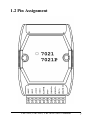
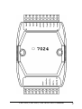
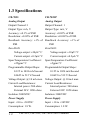
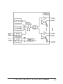
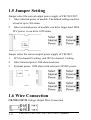
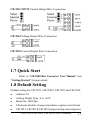
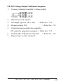
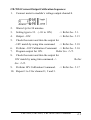
CD-7021/CB7021P & CB-7022, CB-7024 User’s Manual Copyright Sept., 2000. All rights are reserved. CB-7021, CB-7022, CB-7024 User’s Manual 1 Table of Contents 1. Introduction .....................................................6 1.1 More Information.......................................6 1.2 Pin Assignment ..........................................7 1.3 Specifications ..........................................10 1.4 Block Diagram ........................................12 1.5 Jumper Setting .........................................14 1.6 Wire Connection......................................14 1.7 Quick Start ..............................................15 1.8 Default Setting ........................................15 1.9 Calibration ...............................................16 1.10 Configuration Tables .............................22 2. Command .......................................................26 2.1 %AANNTTCCFF ...................................29 2.2 $AA2 .......................................................30 2.3 $AA5 .......................................................31 2.4 $AAF .......................................................32 2.5 $AAM......................................................33 2.6 ~AAO(Data) ............................................34 2.7 #AA(Data) ...............................................35 2.8 $AA0 .......................................................37 2.9 $AA1 .......................................................38 2.10 $AA3VV ...............................................39 2 CB-7021, CB-7022, CB-7024 User’s Manual 2.11 $AA4 .....................................................40 2.12 $AA6 .....................................................41 2.13 $AA7 .....................................................42 2.14 $AA8 .....................................................43 2.15 #AAN(Data) ..........................................45 2.16 $AA0N ..................................................47 2.17 $AA1N ..................................................48 2.18 $AA3NVV.............................................49 2.19 $AA4N ..................................................50 2.20 $AA6N ..................................................51 2.21.1 $AA7N ...............................................52 2.21.2 $AA7N ...............................................53 2.22 $AA8N ..................................................54 2.23 $AA9N ..................................................56 2.24 $AA9NTS..............................................57 2.25 ~** .........................................................58 2.26 ~AA0 .....................................................59 2.27 ~AA1 .....................................................60 2.28 ~AA2 .....................................................61 2.29 ~AA3EVV .............................................62 2.30 ~AA4 .....................................................64 2.31 ~AA4N ..................................................65 2.32 ~AA5 .....................................................66 2.33 ~AA5N ..................................................67 CB-7021, CB-7022, CB-7024 User’s Manual 3 3. Application Note............................................68 3.1 INIT* pin Operation .................................68 3.2 Module Status ..........................................68 3.3 Dual Watchdog Operation ........................69 3.4 Reset Status..............................................69 3.5 Analog Output ..........................................69 3.6 Slew Rate Control ....................................70 3.7 Current Readback.....................................71 HM CB COM 7021-24.p65 4 CB-7021, CB-7022, CB-7024 User’s Manual CB-7021, CB-7022, CB-7024 User’s Manual 5 1. Introduction CB-7000 is a family of network data acquisition and control modules. They provide analog-to-digital, digital-to-analog, digital input/output, timer/counter and other functions. These modules can be remote controlled by a set of commands. The basic features of CB-7021, CB-7021P, CB-7022 and CB-7024 are given as following: l 3000 VDC isolated analog output. l Programmable PowerOn Value of analog output. Programmable slew rate. l Software calibration. The CB-7021 is an analog output module with 12-bit resolution and current readback function. The CB-7021P is similar with CB-7021 but with 16-bit resolution. The CB-7022 is the dual channel version of CB-7021. The CB-7024 is a 4-channel analog output module, and supports bipolar voltage outputs. l 1.1 More Information Refer to “CB-7000 Bus Converter User Manual” chapter 1 for more information as following: 1.1 CB-7000 Overview 1.2 CB-7000 Related Documentation 1.3 CB-7000 Command Features 1.4 CB-7000 System Network Configuration 1.5 CB-7000 Dimension 6 CB-7021, CB-7022, CB-7024 User’s Manual 1.2 Pin Assignment CB-7021, CB-7022, CB-7024 User’s Manual 7 8 CB-7021, CB-7022, CB-7024 User’s Manual CB-7021, CB-7022, CB-7024 User’s Manual 9 1.3 Specifications CB-7021 Analog Output Output Channel: 1 Output Type: mA, V Accuracy: ±0.1% of FSR Resolution: ±0.02% of FSR Readback Accuracy: ±1% of FSR Zero Drift: Voltage output: ±30µV/°C Current output: ±0.2µA/°C Span Temperature Coefficient: ±25ppm/°C Programmable Output Slope: 0.125 to 1024 mA/Second 0.0625 to 512 V/Second Voltage Output: @ 10 mA max. Current Load Resistance: Internal power: 500 ohms External 24V: 1050 ohms Isolation: 3000VDC Power Supply Input: +10 to +30VDC Consumption: 1.8 W. 10 CB-7021P Analog Output Output Channel: 1 Output Type: mA, V Accuracy: ±0.02% of FSR Resolution: ±0.002% of FSR Readback Accuracy: ±1% of FSR Zero Drift: Voltage output: ±10µV/°C Current output: ±0.2µA/°C Span Temperature Coefficient: ±5ppm/°C Programmable Output Slope: 0.125 to 1024 mA/Second 0.0625 to 512 V/Second Voltage Output: @ 10 mA max. Current Load Resistance: Internal power: 500 ohms External 24V: 1050 ohms Isolation: 3000VDC Power Supply Input: +10 to +30VDC Consumption: 1.8 W. CB-7021, CB-7022, CB-7024 User’s Manual CB-7022 CB-7024 Analog Output Analog Output Output Channel: 2 Output Channel: 4 Output Type: mA, V Output Type: mA, V Accuracy: ±0.1% of FSR Accuracy: ±0.1% of FSR Resolution: ±0.02% of FSR Resolution: ±0.02% of FSR Readback Accuracy: ±1% of Zero Drift: FSR Voltage output: ±30µV/°C Zero Drift: Current output: ±0.2µA/°C Voltage output: ±30µV/°C Span Temperature Coefficient: Current output: ±0.2µA/°C ±20ppm/°C Span Temperature Coefficient: Programmable Output Slope: ±25ppm/°C 0.125 to 2048 mA/Second Programmable Output Slope: 0.0625 to 1024 V/Second 0.125 to 1024 mA/Second Voltage Output: @ 5 mA max. 0.0625 to 512 V/Second Current Load Resistance: Voltage Output: @ 10 mA max. External 24V: 1050 ohms Current Load Resistance: Isolation: 3000VDC Internal power: 500 ohms Power Supply External 24V: 1050 ohms Input: +10 to +30VDC Isolation: 3000VDC Consumption: 2.3 W. Channel-to-channel isolation Power Supply Input: +10 to +30VDC Consumption: 3.0 W. CB-7021, CB-7022, CB-7024 User’s Manual 11 1.4 Block Diagram 12 CB-7021, CB-7022, CB-7024 User’s Manual CB-7021, CB-7022, CB-7024 User’s Manual 13 1.5 Jumper Setting Jumper-select the current output power supply of CB-7021/21P: 1. Select internal power of module. The default setting can drive a load of up to 500 ohms. 2. Select external power of module: can drive larger load. With 24V power, it can drive 1050 ohms. Jumper select the current output power supply of CB-7022: 1. JP1 for channel 0 setting, and JP2 for channel 1 setting. 2. Select internal power: 500 ohms load max. 3. External power: 1050 ohms with external +24VDC power. 1.6 Wire Connection CB-7021/21P/22 Voltage Output Wire Connection 14 CB-7021, CB-7022, CB-7024 User’s Manual CB-7021/21P/22 Current Output Wire Connection CB-7024 Voltage Output Wire Connection CB-7024 Current Output Wire Connection 1.7 Quick Start Refer to “CB-7000 Bus Converter User Manual” and “Getting Started” for more detail. 1.8 Default Setting Default setting for CB-7021, CB-7021P, CB-7022 and CB-7024: l Address: 01 l Analog Output Type: 0 to +10V l Baud rate: 9600 bps l Checksum disable, change immediate, engineer unit format l CB-7021, CB-7021P, CB-7022 jumper setting: internal power. CB-7021, CB-7022, CB-7024 User’s Manual 15 1.9 Calibration Don’t Perform Calibration Until You Understand Procedure. CB-7021/21P Current Output Calibration Sequence: 1. Set the jumper 1 to internal power and connect milliammeter to module’s current output. If a milliammeter in not available, use Volt Meter with shunt resistor (250 ohms, 0.1%). Calculate the output current by the Volt Meter value (I = V/250). 2. 3. 4. 5. 6. 7. 8. 9. 16 Warm-Up for 30 minutes. Setting type to 30. (0 to 20 mA) Refer Sec. 2.1. Program output for 4 mA. Refer Sec. 2.7. Check the meter and trim the output until 4 mA match by apply trim command. Refer Sec. 2.10. Preform 4 mA Calibration Command. Refer Sec. 2.8. Program output for 20 mA. Refer Sec. 2.7. Check the meter and trim the output until 20 mA obtained by trim command. Refer Sec. 2.10 Perform 20 mA Calibration Command. Refer Sec. 2.9. CB-7021, CB-7022, CB-7024 User’s Manual CB-7021/21P Voltage Output Calibration Sequence: 1. Connect voltmeter to module’s voltage output. 2. 3. 4. 5. Warm-Up for 30 minutes. Set type to 32. (0 to 10V) Program output for 10V. Check Refer Sec. 2.1. Refer Sec. 2.7. Refer Sec. 2.13. CB-7021, CB-7022, CB-7024 User’s Manual 17 CB-7022 Current Output Calibration Sequence: 1. Set the jumper to internal power and connect milliammeter to module’s current output channel 0. If a milliammeter is not available, use a Volt Meter with shunt resistor (250 ohms, 0.1%), and calculate the mA by the Volt Meter value (I = V/250). 2. Warm-Up for 30 minutes. 3. Set output type to 0. (0 to 20mA) Refer Sec. 2.24. 4. Program output for 4 mA. Refer Sec. 2.15. 5. 6. 7. 8. 9. 10. Check the meter and trim the output for 4 mA match by using trim command. Refer Sec. 2.18. Preform 4 mA Calibration Command. Refer Sec. 2.16. Program output 20 mA. Refer Sec. 2.15. Check the meter and trim the output until 20 mA match by using trim command. Refer Sec. 2.18. Perform 20 mA Calibration Command. Refer Sec. 2.17. Repeat step 1 to 9 for channel 1. 18 CB-7021, CB-7022, CB-7024 User’s Manual CB-7022 Voltage Output Calibration Sequence: 1. Connect voltmeter to module’s voltage output. 2. 3. 4. 5. Warm-Up for 30 minutes. Set output type to 2. (0 to 10V) -> Refer Sec. 2.24. Program output 10V. -> Refer Sec. 2.15. Check the meter and trim the output for 10V match by using trim command. -> Refer Sec. 2.18. 6. Perform 10V Calibration Command. -> Refer Sec. 2.21. 7. Repeat step 1 to 6 for channel 1. CB-7021, CB-7022, CB-7024 User’s Manual 19 CB-7024 Current Output Calibration Sequence: 1. Connect meter and external power source to module’s current output channel 0. 2. 3. 4. 5. 6. 7. 8. 9. 10. Warm-Up for 30 minutes. Set type to 30. (0 to 20 mA) -> Refer Sec. 2.1. Program output for 0 mA. -> Refer Sec. 2.15. Check the meter and trim the output for 0 mA match by using trim command. -> Refer Sec. 2.18. Perform 0 mA Calibration Command. -> Refer Sec. 2.16. Program output for 20 mA. -> Refer Sec. 2.15. Check the meter and trim the output for 20 mA match by using trim command. -> Refer Sec. 2.18. Perform 20 mA Calibration Command. -> Refer Sec. 2.17. Repeat 1 to 9 for channel 1, 2, and 3. 20 CB-7021, CB-7022, CB-7024 User’s Manual CB-7024 Current Output Calibration Sequence: 1. Connect meter to module’s voltage output channel 0. 2. 3. 4. 5. 6. 7. 8. 9. 10. Warm-Up for 30 minutes. Setting type to 33. (−10 to 10V) -> Refer Sec. 2.1. Output −10V. -> Refer Sec. 2.15. Check the meter and trim the output for −10V match by using trim command. -> Refer Sec. 2.18. Perform −10V Calibration Command. -> Refer Sec. 2.16. Program output for 10V. Refer Sec. 2.15. Check the meter and trim the output for 10V match by using trim command. -> Refer Sec. 2.18. Perform 10V Calibration Command. -> Refer Sec. 2.17. Repeat 1 to 9 for channel 1, 2 and 3. CB-7021, CB-7022, CB-7024 User’s Manual 21 1.10 Configuration Tables Baud rate Setting (CC) C ode 03 04 05 06 07 08 09 Baudrate 1200 2400 4800 9600 19200 38400 0A 57600 115200 Analog Output Type Setting (TT) Type Code 30 31 32 33 34 35 3F Min. Output 0 mA 4 mV 0V - 10 V 0V -5 V - Max. Output 20 mA 20 mA +10 V +10 V +5 V +5 V - Note For I- 7021/21P/24 For I- 7024 only For I- 7022 only Data Format Setting (FF) 7 6 5 0 *1 4 3 *2 2 1 0 *3 *1: Checksum Bit: 0=Disable, 1=Enable *2: Slew Rate Control: for CB-7021/21P and CB-7024, Refer Sec. 3.6 for details for CB-7022, set to 0 *3: 00 = Engineering Unit Format 01 = Percent of Span Format (For CB-7021/21P/22) 10 = Hexadecimal Format (For CB-7021/21P/22) 22 CB-7021, CB-7022, CB-7024 User’s Manual Sle w Rate for I-7021/21P and I-7024 V/Se cond mA/Se cond 0000 Immediate V/Se cond mA/Se cond 1000 8 .0 16 . 0 0001 0.0625 0.125 1001 16.0 32. 0 0010 0 . 12 5 0.25 1010 3 2 .0 64.0 0011 0.25 0. 5 1011 6 4 .0 128.0 0100 0 .5 1.0 1100 128.0 256. 0 0101 1.0 2. 0 1101 256.0 5 12 . 0 0110 2 .0 4. 0 1110 5 12 . 0 1024.0 0111 4.0 8. 0 1111 1024.0 2048. 0 Note The config 1111 is for I- 7024 only Analog Output Type and Data Format for I-7021/21P Type Code 30 31 32 Output Range 0 to 20 mA 4 to 20 mA 0 to 10 V Data Format M ax. M in. Engineer Unit 2 0 . 0 00 00.000 % of Span +100.00 +000.00 Hexadecimal FFF 0000 Engineer Unit 2 0 . 0 00 04.000 % of Span +100.00 +000.00 Hexadecimal FFF 0000 Engineer Unit 10.000 00.000 % of Span Hexadecimal +100.00 +000.00 FFF CB-7021, CB-7022, CB-7024 User’s Manual 0000 23 Analog Output Type and Data Format for I-7022 Output Type 0 Output Range 0 to 20 mA 1 4 to 20 mA 2 0 to 10 V Data Format M ax. M in. Engineer Unit 2 0 . 0 00 00.000 % of Span +100.00 +000.00 Hexadecimal FFF 0000 Engineer Unit 2 0 . 0 00 04.000 % of Span +100.00 +000.00 Hexadecimal FFF 0000 Engineer Unit 10.000 00.000 % of Span Hexadecimal +100.00 +000.00 FFF 0000 Analog Output Type and Data Format for I-7024 Type Code Output Range Data Format 30 0 to 20 mA Engineer Unit +20.000 +00.000 31 4 to 20 mA Engineer Unit +20.000 +04.000 32 0 to 10 V Engineer Unit +10.000 +00.000 33 - 10 to +10 V Engineer Unit +10.000 - 10.000 34 0 to +5 V Engineer Unit +05.000 +00.000 35 - 5 to +5 V Engineer Unit +05.000 - 05.000 24 M ax. CB-7021, CB-7022, CB-7024 User’s Manual M in. DA Configuration of CB-7022 Analog Output Type (T) 0 0 mA to 20 mA current output 1 4 mA to 20 mA current output 2 0V to 10V voltage output Slew Rate Control (S) 0 Immediate change 1 0.0625V/Second or 0.125 mA/Second 2 0.125V/Second or 0.25 mA/Second 3 0.25V/Second or 0.5 mA/Second 4 0.5V/Second or 1.0 mA/Second 5 1.0V/Second or 2.0 mA/Second 6 2.0V/Second or 4.0 mA/Second 7 4.0V/Second or 8.0 mA/Second 8 8.0V/Second or 16 mA/Second 9 16V/Second or 32 mA/Second A 32V/Second or 64 mA/Second B 64V/Second or 128 mA/Second C 128V/Second or 256 mA/Second D 256V/Second or 512 mA/Second E 512V/Second or 1024 mA/Second CB-7021, CB-7022, CB-7024 User’s Manual 25 2. Command Command Format: (Leading)(Address)(Command)[CHK](cr) Response Format: (Leading)(Address)(Data)[CHK](cr) [CHK] 2-character checksum (cr) end-of-command character, character returns(0x0D) Calculate Checksum: 1. Calculate ASCII sum of all characters of command (or response) string except the character returns(cr). 2. Mask the sum of string with 0ffh. Example: Command string: $012(cr) Sum of string = ‘$’+‘0’+‘1’+‘2’ = 24h+30h+31h+32h = B7h The checksum is B7h, and [CHK] = “B7” Command string with checksum: $012B7(cr) Response string: !01300600(cr) Sum of string: ‘!’+‘0’+‘1’+‘3’+‘0’+‘0’+‘6’+‘0’+‘0’ = 21h+30h+31h+33h+30h+30h+36h+30h+30h = 1ABh The checksum is ABh, and [CHK] = “AB” Response string with checksum: !01300600AB(cr) Ge ne ral Command Se ts Command Re s pons e %AANNTTCCFF !AA De s cription Set Module Configuration Se ction Sec.2.1 $AA2 !AANNTTCCFF Read Configuration Sec.2.2 $AA5 !AAS Read Reset Status Sec.2.3 $AAF !AA(Data) Read Firmware Version Sec.2.4 $AAM !AA(Data) Read Module Name Sec.2.5 ~AAO(Data) !AA Set Module Name Sec.2.6 26 CB-7021, CB-7022, CB-7024 User’s Manual I-7021/21P Analog Output Command Se ts Command Re s pons e De s cription Se ction #AA(Data) > Output Analog Value Sec.2.7 $AA0 !AA 4mA Calibration Sec.2.8 $AA1 !AA 20mA Calibration Sec.2.9 $AA3VV !AA Trim Calibration Sec.2.10 $AA4 !AA Set PowerOn Value Sec.2.11 $AA6 !AA(Data) Last Value Readback Sec.2.12 $AA7 !AA 10V Calibration Sec.2.13 $AA8 !AA(Data) Current Readback Sec.2.14 I-7022 Analog Output Command Se ts (All command for s pe cificie d channe l N) Command Re s pons e De s cription Se ction #AAN(Data) > Output Analog Value Sec.2.15 $AA0N !AA 4mA Calibration Sec.2.16 $AA1N !AA 20mA Calibration Sec.2.17 $AA3NVV !AA Trim Calibration Sec.2.18 $AA4N !AA Set PowerOn Value Sec.2.19 $AA6N !AA(Data) Last Value Readback Sec.2.20 $AA7N !AA 10V Calibration Sec.2.21.1 $AA8N !AA(Data) Current Readback Sec.2.22 $AA9N !AATS Read DA Configuration Sec.2.23 $AA9NTS !AA Set DA Configuration Sec.2.24 CB-7021, CB-7022, CB-7024 User’s Manual 27 I-7024 Analog Output Command Se ts (All commands for s pe cificie d channe l N) Command Re s pons e De s cription Se ction #AAN(Data) > Output Analog Value Sec.2.15 $AA0N !AA 0mA/- 10V Calibration Sec.2.16 $AA1N !AA 20mA/10V Calibration Sec.2.17 $AA3NVV !AA Trim Calibration Sec.2.18 $AA4N !AA Set PowerOn Value Sec.2.19 $AA6N !AA(Data) Last Value Readback Sec.2.20 $AA7N !AA Read PowerOn Value Sec.2.21.2 $AA8N !AA(Data) Current Value Readback Sec.2.22 Hos t Watchdog Re late d Command Se ts Command Re s pons e De s cription Sect i on ~ ** No Response Host OK Sec.2.25 ~AA0 !AASS Read Module Status Sec.2.26 ~AA1 !AA Reset Module Status Sec.2.27 ~AA2 !AAVV Read Host Watchdog Timeout Value Sec.2.28 ~AA3EVV !AA Set Host Watchdog Timeout Value Sec.2.29 ~AA4 !AA(Data) Read Safe Value Sec.2.30 ~AA4N !AA(Data) Read Safe Value of Channel N Sec.2.31 ~AA5 !AA Set Safe Value Sec.2.32 ~AA5N !AA Set Safe Value of Channel Sec.2.33 N 28 CB-7021, CB-7022, CB-7024 User’s Manual 2.1 %AANNTTCCFF Description: Set module Configuration Syntax: %AANNTTCCFF[CHK](cr) % Delimiter character AA Address of setting module (00 to FF) NN New address for setting module (00 to FF) TT New type for setting module (Ref Sec. 1.10) CC New baud rate for setting module (Ref Sec. 1.10) FF New data format for setting module (Ref Sec. 1.10) When changing the baud rate or checksum, short the INIT* pin to ground. Response: Valid Command: !AA[CHK](cr) Invalid Command: ?AA[CHK](cr) Syntax error or communication error may get no response. ! Delimiter for valid command ? Delimiter for invalid command. While changing baud rate or checksum setting without shorting INIT* to ground, the module will returns an invalid command message. AA Address of response module (00 to FF) Example: Command: %0102300600 Receive: !02 Change address from 01 to 02, returns successful. Related Command: Sec. 2.2 $AA2 Related Topics: Sec. 1.10 Configuration Tables, Sec. 3.1 INIT* pin Operation CB-7021, CB-7022, CB-7024 User’s Manual 29 2.2 $AA2 Description: Read Configuration Syntax: $AA2[CHK](cr) $ Delimiter character AA Address of reading module (00 to FF) 2 Command for reading configuration Response: Valid Command: !AATTCCFF[CHK](cr) Invalid Command: ?AA[CHK](cr) Syntax error or comm. error may get no response. ! Delimiter for valid command ? Delimiter for invalid command AA Address of response module (00 to FF) TT Type code of module (reference Sec. 1.10) CC Baud rate code of module (reference Sec. 1.10) FF Data format of module (reference Sec. 1.10) Example: Command: $012 Receive: !01300600 Read configuration of module in address 01, which is an CB7021 module, returns analog output 0 to 20 mA, baud rate 9600bps, no checksum, engineering unit format and output change immediate. Related Command: Sec. 2.1 %AANNTTCCFF Related Topics: Sec. 1.10 Configuration Tables, Sec3.1 INIT* pin Operation 30 CB-7021, CB-7022, CB-7024 User’s Manual 2.3 $AA5 Description: Read Reset Status Command: $AA5[CHK](cr) $ Delimiter character AA Address of reading module (00 to FF) 5 Command for reading reset status Response: Valid Command: !AAS[CHK](cr) Invalid Command: ?AA[CHK](cr) Syntax or communication error may get no response. ! Delimiter for valid command ? Delimiter for invalid command AA Address of response module (00 to FF) S Reset status, 1 = the module is been reset; 0 = the module is not been reset. Example: Command: $015 Receive: !011 Read address 01 reset status, returns first read. Command: $015 Receive: !010 Read address 01 reset status, returns no reset occurred. Related Topics: Sec3.4, Reset Status CB-7021, CB-7022, CB-7024 User’s Manual 31 2.4 $AAF Description: Read Firmware Version Syntax: $AAF[CHK](cr) $ Delimiter character AA Address of reading module (00 to FF) F command for reading firmware version Response: Valid Command: !AA(Data)[CHK](cr) Invalid Command: ?AA[CHK](cr) Syntax error or communication error may get no response. ! Delimiter for valid command ? Delimiter for invalid command AA Address of response module (00 to FF) (Data) firmware version of module Example: Command: $01F Receive: !01A2.0 Read address 01 firmware version, returns version A2.0. Command: $02F Receive: !01B1.1 Read address 02 firmware version, returns version B1.1. 32 CB-7021, CB-7022, CB-7024 User’s Manual 2.5 $AAM Description: Read Module Name Syntax: $AAM[CHK](cr) $ Delimiter character AA Address of reading module (00 to FF) M Command for reading module name Response: Valid Command: !AA(Data)[CHK](cr) Invalid Command: ?AA[CHK](cr) Syntax error or communication error may get no response. ! Delimiter for valid command ? Delimiter for invalid command AA Address of response module (00 to FF) (Data) Name of module Example: Command: $01M Receive: !017021 Read address 01 module name, returns name 7021. Command: $03M Receive: !037021P Read address 03 module name, returns name 7021P. Related Command: Sec. 2.6 ~AAO(Data) CB-7021, CB-7022, CB-7024 User’s Manual 33 2.6 ~AAO(Data) Description: Set Module Name Syntax: ~AAO(Data)[CHK](cr) ~ Delimiter character AA Address of setting module (00 to FF) O Command for setting module name (Data) New name for module, max 6 characters Response: Valid Command: !AA[CHK](cr) Invalid Command: ?AA[CHK](cr) Syntax error or communication error may get no response. ! Delimiter for valid command ? Delimiter for invalid command AA Address of response module (00 to FF) Example: Command: ~01O7021 Receive: !01 Set address 01 module name to 7021, returns successfulful. Command: $01M Receive: !017021 Read address 01 module name, returns 7021. Related Command: Sec. 2.5 $AAM 34 CB-7021, CB-7022, CB-7024 User’s Manual 2.7 #AA(Data) Description: Output Analog Value Note: The command is for CB-7021/21P only. Syntax: #AA(Data)[CHK](cr) # Delimiter character AA Address of output module (00 to FF) (Data) analog output value, reference Sec. 1.10 for its format. Response: Valid Command: >[CHK](cr) Out of Range: ?AA[CHK](cr) Ignore Command:  Syntax error or communication error may get no response. > Delimiter for valid command ? Delimiter while the (Data) is out of range, and the output will go to the closest value in the setting of module’s range. ! Delimiter for the module’s host watchdog flag is set, and the output command will be ignored and the output is set to Safe Value. AA Address of response module (00 to FF) Example: Command: $012 Receive: !01300600 Read Address 01 configuration, returns output type 0 to 20 mA, engineer unit format and output change immediate. Command: #0105.000 Receive: > Output address 01 value 5.0 mA, returns successful. Command: #0125.000 Receive: ?01 Output address 01 value 25.0 mA, returns the value is out of CB-7021, CB-7022, CB-7024 User’s Manual 35 range, and the output is set to 20.0 mA. Command: $022 Receive: !02300601 Read address 02 configuration, returns output type 0 to 20 mA, percent of span format, output change immediate. Command: #02+050.00 Receive: > Output address 02 value 50% (=10 mA), returns successful. Command: $032 Receive: !02300602 Read address 03 configuration, returns output type 0 to 20 mA, hexadecimal format, output change immediate. Command: #03800 Receive: > Output address 03 value 0x800 (=10 mA), returns successful. Related Command: Sec. 2.1 %AANNTTCCFF, Sec. 2.2 $AA2 Related Topics: Sec. 1.10 Configuration Tables, Sec. 3.5 Analog Output 36 CB-7021, CB-7022, CB-7024 User’s Manual 2.8 $AA0 Description: Perform 4 mA Calibration Note: The command is for CB-7021/21P only. Syntax: $AA0[CHK](cr) $ Delimiter character AA Address of setting module (00 to FF) 0 command for performing 4 mA calibration Response: Valid Command: !AA[CHK](cr) Invalid Command: ?AA[CHK](cr) Syntax error or communication error may get no response. ! Delimiter for valid command ? Delimiter for invalid command AA Address of response module (00 to FF) Example: Command: $010 Receive: !01 Perform address 01 4 mA calibration, returns successful. Related Command: Sec. 2.9 $AA1, Sec. 2.10 $AA3VV Related Topics: Sec. 1.9 Calibration CB-7021, CB-7022, CB-7024 User’s Manual 37 2.9 $AA1 Description: Perform 20 mA Calibration Note: The command is for CB-7021/21P only. Syntax: $AA1[CHK](cr) $ Delimiter character AA Address of setting module (00 to FF) 1 command for performing 20 mA calibration Response: Valid Command: !AA[CHK](cr) Invalid Command: ?AA[CHK](cr) Syntax error or communication error may get no response. ! Delimiter for valid command ? Delimiter for invalid command AA Address of response module (00 to FF) Example: Command: $011 Receive: !01 Perform address 01 20 mA calibration, returns successful. Related Command: Sec. 2.8 $AA0, Sec. 2.10 $AA3VV Related Topics: Sec. 1.9 Calibration 38 CB-7021, CB-7022, CB-7024 User’s Manual 2.10 $AA3VV Description: Trim Calibration Note: The command is for CB-7021/21P only. Syntax: $AA3VV[CHK](cr) $ Delimiter character AA Address of setting module (00 to FF) 3 Command for trimming calibration VV 2’s complement hexadecimal to trim the analog output value. 00 to 5F to increase 0 to 95 counts, and FF to A1 to decrease 1 to 95 counts. Each count indicates 4.88µA or 2.44mV. Response: Valid Command: !AA[CHK](cr) Invalid Command: ?AA[CHK](cr) Syntax error or comm. error may get no response. ! Delimiter for valid command ? Delimiter for invalid command AA Address of response module (00 to FF) Example: Command: $0131F Receive: !01 Trim address 01 output to increase 31 counts, returns successful. Related Command: Sec. 2.8 $AA0, Sec. 2.9 $AA1, Sec. 2.13 $AA7 Related Topics: Sec. 1.9 Calibration CB-7021, CB-7022, CB-7024 User’s Manual 39 2.11 $AA4 Description: Set PowerOn Value Note: The command is for CB-7021/21P only. Syntax: $AA4[CHK](cr) $ Delimiter character AA Address of setting module (00 to FF) 4 Command for setting PowerOn Value. Store the current output value as PowerOn Value. Response: Valid Command: !AA[CHK](cr) Invalid Command: ?AA[CHK](cr) Syntax error or communication error may get no response. ! Delimiter for valid command ? Delimiter for invalid command AA Address of response module (00 to FF) Example: Command: #0100.000 Receive: > Set address 01 output 0.0 mA, returns successful. Command: $014 Receive: !01 Set address 01 PowerOn Value, returns successful. The module 01 will go to 0.0 mA with module power on. Related Command: Sec. 2.7 #AA(Data) Related Topics: Sec. 3.5 Analog Output 40 CB-7021, CB-7022, CB-7024 User’s Manual 2.12 $AA6 Description: Last Value Readback Note: The command is for CB-7021/21P only. Syntax: $AA6[CHK](cr) $ Delimiter character AA Address of reading module (00 to FF) 6 Command for reading last output command value Response: Valid Command: !AA(Data)[CHK](cr) Invalid Command: ?AA[CHK](cr) Syntax error or communication error may get no response. ! Delimiter for valid command ? Delimiter for invalid command AA Address of response module (00 to FF) (Data) The last output command value. If no output applied to the module, the (Data) is the PowerOn Value of the module. Refer to Sec. 1.10 for formatting. Example: Command: #0110.000 Receive: !01 Set address 01 output 10.0, returns successful. Command: $016 Receive: !0110.000 Read address 01 last output command value, returns 10.000. Related Command: Sec. 2.7 #AA(Data), Sec. 2.14 $AA8 Related Topics: Sec. 3.7, Current Readback CB-7021, CB-7022, CB-7024 User’s Manual 41 2.13 $AA7 Description: Perform 10V Calibration Note: The command is for CB-7021/21P only. Syntax: $AA7[CHK](cr) $ Delimiter character AA Address of setting module (00 to FF) 1 command for performing 10V calibration Response: Valid Command: !AA[CHK](cr) Invalid Command: ?AA[CHK](cr) Syntax error or communication error may get no response. ! Delimiter for valid command ? Delimiter for invalid command AA Address of response module (00 to FF) Example: Command: $017 Receive: !01 Perform address 01 10V calibration, returns successful. Related Command: Sec. 2.10 $AA3VV Related Topics: Sec. 1.9 Calibration 42 CB-7021, CB-7022, CB-7024 User’s Manual 2.14 $AA8 Description: Current Readback Note: The command is for CB-7021/21P only. Syntax: $AA6[CHK](cr) $ Delimiter character AA Address of reading module (00 to FF) 8 Command for current readback Response: Valid Command: !AA(Data)[CHK](cr) Invalid Command: ?AA[CHK](cr) Syntax error or communication error may get no response. ! Delimiter for valid command ? Delimiter for invalid command AA Address of response module (00 to FF) (Data) The current output value. Refer to Sec. 1.9 for format. Example: Command: $012 Receive: !01320614 Read address 01 configuration, returns output type 0 to 10V, 9600 bps, eng. unit format and slew rate is 1.0V/Second. Command: #0110.000 Receive: !01 Set address 01 output 10.0V, returns successful. Command: $016 Receive: !0110.000 Read address 01 last output command value, returns 10.000. Command: $018 Receive: !0101.000 Read address 01 current value, returns 1.0V. Command: $018 Receive: !0101.500 CB-7021, CB-7022, CB-7024 User’s Manual 43 Read address 01 current value, returns 1.5V. Related Command: Sec. 2.7 #AA(Data), Sec. 2.12 $AA6 Related Topics: Sec. 3.6 Slew Rate Control, Sec. 3.7 Current Readback 44 CB-7021, CB-7022, CB-7024 User’s Manual 2.15 #AAN(Data) Description: Output Analog Value for Channel N Note: The command is for CB-7022 and CB-7024 only. Syntax: #AAN(Data)[CHK](cr) # Delimiter character AA Address of output module (00 to FF) N Output channel (0 to 1 for CB-7022, 0 to 3 for CB7024) (Data) Analog output value, reference Sec. 1.10 for its format. Response: Valid Command: >[CHK](cr) Invalid Command: ?AA[CHK](cr) Ignore Command:  Syntax error or communication error may get no response. > Delimiter for valid command ? Delimiter for invalid command. When the (Data) is out of range, and the output will go to the closest value in the module’s range. ! Delimiter for the module’s host watchdog status is set, and the output command will be ignored. AA Address of response module (00 to FF) Example for CB-7022: Command: $012 Receive: !013F0600 Read address 01 configuration, returns multichannel output, 9600 bps and engineering unit format. Command: $0190 Receive: !0110 CB-7021, CB-7022, CB-7024 User’s Manual 45 Read address 01, channel 0 DA config., returns 4 to 20 mA. output and change immediate. Command: #01005.000 Receive: > Output address 01 channel 0 value 5.0 mA, returns successful. Command: #01025.000 Receive: ?01 Output address 01 channel 0 value 25 mA, returns out of range, and the output of channel 0 is set to the 20.0 mA Example for CB-7024: Command: $012 Receive: !01300600 Read address 01 configuration, returns type 0 to 20mA, 9600 bps and engineer unit format, output change immediate. Command: #010+05.000 Receive: > Output address 01 channel 0 value 5.0 mA, returns successful. Command: #010+25.000 Receive: ?01 Output address 01 channel 0 value 25.0 mA, returns the value is out of range, and the output of channel 0 is set to the 20.0 mA. Related Command: Sec. 2.1 %AANNTTCCFF, Sec. 2.2 $AA2 Related Topics: Sec. 1.10 Configuration Tables, Sec. 3.5 Analog Output 46 CB-7021, CB-7022, CB-7024 User’s Manual 2.16 $AA0N Description: CB-7022: Perform 4 mA Calibration for Channel N CB-7024: Perform 0 mA/-10V Calibration for Channel N Note: The command is for CB-7022 and CB-7024 only. Syntax: $AA0N[CHK](cr) $ Delimiter character AA Address of setting module (00 to FF) 0 command for doing 4 mA (or 0 mA/-10V) calibration N channel to calibrate (0 to 1 for CB-7022, 0 to 3 for CB7024) Response: Valid Command: !AA[CHK](cr) Invalid Command: ?AA[CHK](cr) Syntax error or communication error may get no response. ! Delimiter for valid command ? Delimiter for invalid command AA Address of response module (00 to FF) Example: Command: $0101 Receive: !01 Perform Address 01 channel 1 calibration (4 mA for CB-7022, 0 mA or -10.0V for CB-7024), returns successful. Related Command: Sec. 2.17 $AA1N, Sec. 2.18 $AA3NVV Related Topics: Sec. 1.9 Calibration CB-7021, CB-7022, CB-7024 User’s Manual 47 2.17 $AA1N Description: CB-7022: Perform 20 mA Calibration for Channel N CB-7024: Perform 20 mA/+10V Calibration for Channel N Note: The command is for CB-7022 and CB-7024 only. Syntax: $AA1N[CHK](cr) $ Delimiter character AA Address of setting module (00 to FF) 1 Command for perform 20 mA (or +10V) calibration N Channel to calibrate (0 to 1 for CB-7022, 0 to 3 for CB-7024) Response: Valid Command: !AA[CHK](cr) Invalid Command: ?AA[CHK](cr) Syntax error or communication error may get no response. ! Delimiter for valid command ? Delimiter for invalid command AA Address of response module (00 to FF) Example: Command: $0112 Receive: !01 Perform address 01 channel 1 calibration (20 mA for CB-7022, 20 mA or 10.0V for CB-7024), returns successful. Related Command: Sec. 2.16 $AA0N, Sec. 2.18 $AA3NVV Related Topics: Sec. 1.9 Calibration 48 CB-7021, CB-7022, CB-7024 User’s Manual 2.18 $AA3NVV Description: Trim Calibration for Channel N Note: The command is for CB-7022 and CB-7024 only Syntax: $AA3NVV[CHK](cr) $ Delimiter character AA Address of setting module (00 to FF) 3 Command for trimming calibration N Channel to trim (0 to 1 for CB-7022, 0 to 3 for CB-7024) VV 2’s complement hex to trim output value. 00 to 5F to increase 0 to 95 counts, and FF to A1 to decrease 1 to 95 counts. A count = 4.88µA/2.44mV for CB-7022 and 2.44µA or 1.22mV for CB-7024. Response: Valid Command: !AA[CHK](cr) Invalid Command: ?AA[CHK](cr) Syntax or comm. error may not get response. ! Delimiter for valid command ? Delimiter for invalid command AA Address of response module (00 to FF) Example: Command: $01321F Receive: !01 Trim address 01 channel 2 output 31 counts, returns OK Related Command: Sec. 2.16 $AA0N, Sec. 2.17 $AA1N Related Topics: Sec. 1.9 Calibration CB-7021, CB-7022, CB-7024 User’s Manual 49 2.19 $AA4N Description: Set PowerOn Value for Channel N Note: The command is for CB-7022 and CB-7024 only. Syntax: $AA4N[CHK](cr) $ Delimiter character AA Address of setting module (00 to FF) 4 Command for setting PowerOn Value, store the current output value as PowerOn Value. N Channel to set (0 to 1 for CB-7022, 0 to 3 for CB-7024) Response: Valid Command: !AA[CHK](cr) Invalid Command: ?AA[CHK](cr) Syntax error or communication error may not get response. ! Delimiter for valid command ? Delimiter for invalid command AA Address of response module (00 to FF) Example for CB-7024: Command: #012+00.000 Receive: > Set address 01 channel 2 output 0.0, returns successful. Command: $0142 Receive: !01 Set address 01 channel 2 PowerOn Value, returns successful. The Power-On Value of channel 2 is set to 0.0 now. Related Command: Sec. 2.15 #AAN(Data), Sec. 2.21 $AA7N Related Topics: Sec. 1.10, Configuration Tables; Sec. 3.5, Analog Output 50 CB-7021, CB-7022, CB-7024 User’s Manual 2.20 $AA6N Description: Last Value of Channel N Readback Note: The command is for CB-7022 and CB-7024 only. Syntax: $AA6N[CHK](cr) $ Delimiter character AA Address of reading module (00 to FF) 6 Command for reading last output command value N Channel to readback (0 to 1 for CB-7022, 0 to 3 for CB7024) Response: Valid Command: !AA(Data)[CHK](cr) Invalid Command: ?AA[CHK](cr) Syntax or comm. error may not get response. ! Delimiter for valid command ? Delimiter for invalid command AA Address of response module (00 to FF) (Data) Last output command value. See Sec. 1.9 for format. Example for CB-7024: Command: #013+10.000 Receive: !01 Set address 01 channel 3 output 10.0, returns successful. Command: $0163 Receive: !01+10.000 Read address 01 channel 3 last output command value, returns 10.000. Related Command: Sec. 2.15, #AAN (Data); Sec. 2.22, $AA8N Related Topics: Sec. 3.7, Current Readback CB-7021, CB-7022, CB-7024 User’s Manual 51 2.21.1 $AA7N Description: Perform 10V Calibration for Channel N Note: The command is for CB-7022 only. Syntax: $AA7N[CHK](cr) $ Delimiter character AA Address of reading module (00 to FF) 7 command for performing 10V calibration N channel to calibrate (0 to 1) Response: Valid Command: !AA[CHK](cr) Invalid Command: ?AA[CHK](cr) Syntax error or communication error may get no response. ! Delimiter for valid command ? Delimiter for invalid command AA Address of response module (00 to FF) Example: Command: $0170 Receive: !01 Perform address 01 channel 0 10V calibration, returns successful. Related Command: Sec. 2.16, $AA0N, Sec. 2.17, $AA1N Related Topics: Sec. 1.9, Calibration 52 CB-7021, CB-7022, CB-7024 User’s Manual 2.21.2 $AA7N Description: Read PowerOn Value of Channel N Note: The command is for CB-7024 only. Syntax: $AA7N[CHK](cr) $ Delimiter character AA Address of reading module (00 to FF) 7 Command for reading PowerOn Value N Channel to readback (0 to 3) Response: Valid Command: !AA(Data)[CHK](cr) Invalid Command: ?AA[CHK](cr) Syntax error or communication error may not get response. ! Delimiter for valid command ? Delimiter for invalid command AA Address of response module (00 to FF) (Data) Last output command value. See Sec. 1.9 for the format. Example: Command: $0170 Receive: !01+00.000 Read address 01 channel 0 PowerOn Value, returns +10.0. Related Command: Sec. 2.19, $AA4N CB-7021, CB-7022, CB-7024 User’s Manual 53 2.22 $AA8N Description: Current Value of Channel N Readback Note: The command is for CB-7022 and CB-7024 only. Syntax: $AA8N[CHK](cr) $ Delimiter character AA Address of reading module (00 to FF) 8 Command for read current output value N Channel to readback (0 to 1 for CB-7022, 0 to 3 for CB7024) Response: Valid Command: !AA(Data)[CHK](cr) Invalid Command: ?AA[CHK](cr) Syntax error or communication error may not get response. ! Delimiter for valid command ? Delimiter for invalid command AA Address of response module (00 to FF) (Data) Last output command value. See Sec. 1.9 for format. Example for CB-7024: Command: $012 Receive: !01320614 Read address 01 configuration, returns output type 0 to 10V, 9600 bps, engineer unit format and slew rate is 1.0V/Second. Command: #010+10.000 Receive: !01 Set address 01 channel 0 output 10.0V, returns successful. Command: $0160 Receive: !01+10.000 Read address 01 channel 0 last output command value, returns 10.000. 54 CB-7021, CB-7022, CB-7024 User’s Manual Command: $0180 Receive: !01+01.000 Read address 01 channel 0 current value, returns 1.0V. Command: $0180 Receive: !01+01.500 Read address 01 channel 0 current value, returns 1.5V. Related Command: Sec. 2.15, #AAN(Data); Sec. 2.20, $AA6N Related Topics: Sec. 3.7, Current Readback CB-7021, CB-7022, CB-7024 User’s Manual 55 2.23 $AA9N Description: Read DA Configuration of Channel N Note: The command is for CB-7022 only. Syntax: $AA9N[CHK](cr) $ Delimiter character AA Address of reading module (00 to FF) 9 Command for reading DA configuration N Channel to read DA configuration (0 to 1) Response: Valid Command: !AATS[CHK](cr) Invalid Command: ?AA[CHK](cr) Syntax error or communication error may not get a response. ! Delimiter for valid command ? Delimiter for invalid command AA Address of response module (00 to FF) T Analog output type. See Sec. 1.10 for format. S Analog output slew rate. See Sec. 1.10 for format. Example: Command: $0190 Receive: !0110 Read address 01 channel 0 DA configuration, returns 4 to 20 mA output and change immediate. Related Command: Sec. 2.24, $AA9NTS 56 CB-7021, CB-7022, CB-7024 User’s Manual 2.24 $AA9NTS Description: Set DA Configuration of Channel N Note: The command is for CB-7022 only. Syntax: $AA9NTS[CHK](cr) $ Delimiter character AA Address of reading module (00 to FF) 9 Command for setting DA configuration N Channel to set DA configuration (0 to 1) T Analog output type. Refer Sec. 1.10 for type select S Analog output slew rate. Refer Sec. 1.10 for slew rate select Response: Valid Command: !AA[CHK](cr) Invalid Command: ?AA[CHK](cr) Syntax error or communication error may not get a response. ! Delimiter for valid command ? Delimiter for invalid command AA Address of response module (00 to FF) Example: Command: $019121 Receive: !01 Set address 01 channel 1 DA configuration: 0 to 10V output and slew rate 0.625V/Second, returns successful. Related Command: Sec. 2.23 $AA9N CB-7021, CB-7022, CB-7024 User’s Manual 57 2.25 ~** Description: Host OK. Host sends this command to all modules broadcasting that the host is OK. Command: ~**[CHK](cr) ~ Delimiter character ** command for all modules Response: No response. Example: Command: ~** No response Send Host OK to all modules. Related Command: Sec. 2.26, ~AA0; Sec. 2.27, ~AA1; Sec. 2.28, ~AA2; Sec. 2.29, ~AA3EVV; Sec. 2.30, ~AA4; Sec. 2.31, ~AA4N; Sec. 2.32, ~AA5; Sec. 2.33, ~AA5N Related Topic: Sec. 3.2, Module Status; Sec. 3.3, Dual Watchdog Operation 58 CB-7021, CB-7022, CB-7024 User’s Manual 2.26 ~AA0 Description: Read Module Status Syntax: ~AA0[CHK](cr) ~ Delimiter character AA Address of reading module (00 to FF) 0 Command for reading module status Response: Valid Command: !AASS[CHK](cr) Invalid Command: ?AA[CHK](cr) Syntax error or communication error may not get response. ! Delimiter for valid command ? Delimiter for invalid command AA Address of response module (00 to FF) SS Module Status. The status will store into EEPROM and only may reset by the command ~AA1. 7 *1 6 5 4 Reserved 3 2 *2 1 0 Reserved *1: Host watchdog enable flag, 0=Disable, 1=Enable *2: Host watchdog timeout flag, 0=Clear, 1=Set Example: Command: ~010 Receive: !0104 Read address 01 module status, returns 04, host watchdog timeout flag is set. Related Command: Sec. 2.27, ~AA1; Sec2.29, ~AA3EVV Related Topic: Sec. 3.2, Module Status; Sec. 3.3, Dual Watchdog Operation CB-7021, CB-7022, CB-7024 User’s Manual 59 2.27 ~AA1 Description: Reset Module Status Command: ~AA1[CHK](cr) ~ Delimiter character AA Address of setting module (00 to FF) 1 Command for reset module status Response: Valid Command: !AA[CHK](cr) Invalid Command: ?AA[CHK](cr) Syntax or communication error may not get a response. ! Delimiter for valid command ? Delimiter for invalid command AA Address of response module (00 to FF) Example: Command: ~010 Receive: !0104 Read address 01 module status, returns 04, host watchdog timeout flag is set. Command: ~011 Receive: !01 Reset address 01 module status, returns successful. Command: ~010 Receive: !0100 Read address 01 module status, returns 00, Module Status is clear. Related Command: Sec. 2.25, ~**; Sec. 2.26, ~AA0 Related Topic: Sec. 3.2, Module Status; Sec. 3.3, Dual Watchdog Operation 60 CB-7021, CB-7022, CB-7024 User’s Manual 2.28 ~AA2 Description: Read Host Watchdog Timeout Interval Command: ~AA2[CHK](cr) ~ Delimiter character AA Address of reading module (00 to FF) 2 Command for reading host watchdog timeout interval Response: Valid Command: !AAEVV[CHK](cr) Invalid Command: ?AA[CHK](cr) Syntax or communication error may not get a response. ! Delimiter for valid command ? Delimiter for invalid command AA Address of response module (00 to FF) E 1=Enable/0=Disable host watchdog VV Timeout interval in hexadecimal format, count for 0.1 second, 01 = 0.1 second and FF = 25.5 seconds Example: Command: ~012 Receive: !010FF Read address 01 host watchdog timeout interval, returns host watchdog disable, and time interval is 25.5 seconds. Related Command: Sec. 2.25, ~**; Sec. 2.26, ~AA0; Sec. 2.27, ~AA1; Sec. 2.29, ~AA3EVV; Sec. 2.30, ~AA4; Sec. 2.31, ~AA4N; Sec. 2.32, ~AA5; Sec. 2.33, ~AA5N Related Topic: Sec. 3.2, Module Status; Sec. 3.3, Dual Watchdog Operation CB-7021, CB-7022, CB-7024 User’s Manual 61 2.29 ~AA3EVV Description: Set Host Watchdog Timeout Interval Command: ~AA3EVV[CHK](cr) ~ Delimiter character AA Address of setting module (00 to FF) 3 Command for setting host watchdog timeout value E 1=Enable/0=Disable host watchdog VV Timeout interval, from 01 to FF, each for 0.1 second Response: Valid Command: !AA[CHK](cr) Invalid Command: ?AA[CHK](cr) Syntax error or communication error may get no response. ! Delimiter for valid command ? Delimiter for invalid command AA Address of response module (00 to FF) Example: Command: ~010 Receive: !0100 Read address 01 module status, returns host watchdog timeout flag is clear and host watchdog is disabled. Command: ~013164 Receive: !01 Set address 01 host watchdog timeout interval 10.0 seconds and enable host watchdog, returns successful. Command: ~012 Receive: !0164 Read address 01 host watchdog timeout interval, returns 10.0 seconds. Command: ~** Receive: no response 62 CB-7021, CB-7022, CB-7024 User’s Manual Reset the host watchdog timer. Wait for about 10 seconds and don’t send command ~**, the LED of module will go to flash. Command: ~010 Receive: !0104 Read address 01 module status, returns host watchdog timeout flag is set and host watchdog is disabled. Command: ~011 Receive: !01 Reset address 01 module status, returns successful. Related Command: Sec. 2.25 ~**, Sec. 2.26 ~AA0, Sec. 2.27 ~AA1, Sec. 2.28 ~AA2, Sec. 2.30 ~AA4, Sec. 2.31 ~AA4N, Sec. 2.32 ~AA5, Sec. 2.33 ~AA5N Related Topic: Sec. 3.2 Module Status, Sec. 3.3 Dual Watchdog Operation CB-7021, CB-7022, CB-7024 User’s Manual 63 2.30 ~AA4 Description: Read Safe Value. Note: The command is for CB-7021/21P only. Command: ~AA4[CHK](cr) ~ Delimiter character AA Address of reading module (00 to FF) 4 Command for read Safe Value Response: Valid Command: !AA(Data)[CHK](cr) Invalid Command: ?AA[CHK](cr) Syntax error or communication error may not get a response. ! Delimiter for valid command ? Delimiter for invalid command AA Address of response module (00 to FF) (Data) Safe Value of module. Refer Sec. 1.10 for data format Example: Command: ~014 Receive: !0105.000 Read address 01 Safe Value, returns 5.0. Related Command: Sec. 2.25, ~**; Sec. 2.26, ~AA0; Sec. 2.27, ~AA1; Sec. 2.28, ~AA2; Sec. 2.29, ~AA3EVV; Sec. 2.32, ~AA5 Related Topic: Sec. 3.2, Module Status; Sec. 3.3, Dual Watchdog Operation 64 CB-7021, CB-7022, CB-7024 User’s Manual 2.31 ~AA4N Description: Read Safe Value of Channel N Note: The command is for CB-7022 and CB-7024 only. Command: ~AA4N[CHK](cr) ~ Delimiter character AA Address of reading module (00 to FF) 4 Command for reading Safe Value N Channel to read (0 to 1 for CB-7022, 0 to 3 for CB7024) Response: Valid Command: !AA(Data)[CHK](cr) Invalid Command: ?AA[CHK](cr) Syntax error or communication error may not get a response. ! Delimiter for valid command ? Delimiter for invalid command AA Address of response module (00 to FF) (Data) Safe Value of module. Refer Sec. 1.10 for data format. Example for CB-7024: Command: ~0140 Receive: !01+00.000 Read address 01 channel 0 Safe Value, returns +0.0. Related Command: Sec. 2.25, ~**; Sec. 2.26, ~AA0; Sec. 2.27, ~AA1; Sec. 2.28, ~AA2; Sec. 2.29, ~AA3EVV; Sec. 2.33, ~AA5N Related Topic: Sec. 3.2, Module Status; Sec. 3.3, Dual Watchdog Operation CB-7021, CB-7022, CB-7024 User’s Manual 65 2.32 ~AA5 Description: Set Safe Value. Note: The command is for CB-7021/21P only. Command: ~AA5[CHK](cr) ~ Delimiter character AA Address of setting module (00 to FF) 5 Command to store current output as Safe Value Response: Valid Command: !AA[CHK](cr) Invalid Command: ?AA[CHK](cr) Syntax or communication error may not get a response. ! Delimiter for valid command ? Delimiter for invalid command AA Address of response module (00 to FF) Example: Command: #0100.000 Receive: !01 Output address 01 value 0.0, returns successful. Command: ~015 Receive: !01 Set address 01 Safe Value, returns successful. Related Command: Sec. 2.25, ~**; Sec. 2.26, ~AA0; Sec. 2.27, ~AA1; Sec. 2.28, ~AA2; Sec. 2.29, ~AA3EVV; Sec. 2.30, ~AA4 Related Topic: Sec. 3.2, Module Status; Sec. 3.3, Dual Watchdog Operation 66 CB-7021, CB-7022, CB-7024 User’s Manual 2.33 ~AA5N Description: Set Safe Value of Channel N Note: The command is for CB-7022 and CB-7024 only. Command: ~AA5N[CHK](cr) ~ Delimiter character AA Address of setting module (00 to FF) 5 Command to store current output as Safe Value N Channel to set (0 to 1 for CB-7022, 0 to 3 for CB-7024) Response: Valid Command: !AA[CHK](cr) Invalid Command: ?AA[CHK](cr) Syntax or communication error may not get a response. ! Delimiter for valid command ? Delimiter for invalid command AA Address of response module (00 to FF) Example for CB-7024: Command: #010+05.000 Receive: !01 Output address 01 channel 0 value +5.0, returns successful. Command: ~0150 Receive: !01 Set address 01 channel 0 Safe Value, returns successful. Related Command: Sec. 2.25, ~**; Sec. 2.26, ~AA0; Sec. 2.27, ~AA1; Sec. 2.28, ~AA2; Sec. 2.29, ~AA3EVV; Sec. 2.31, ~AA4N Related Topic: Sec. 3.2, Module Status; Sec. 3.3, Dual Watchdog Operation CB-7021, CB-7022, CB-7024 User’s Manual 67 3. Application Note 3.1 INIT* pin Operation Each CB-7000 module has a build-in EEPROM to store configuration information such as address, type, baud rate and other information. Sometimes, a user may forget the configuration of the module. Therefore, the CB-7000 have a special mode named “INIT mode”, to help user to resolve this problem. The “INIT mode” is setting as Address=00, baud rate=9600bps, no checksum. To enable INIT mode, please follow these steps: Step 1. Power-down the module. Step 2. Connect the INIT* pin with the GND pin. Step 3. Power-up the module. Step 4. Send command $002(cr) in 9600 bps to read the configuration stored in the module’s EEPROM. Refer to “7000 Bus Converter User Manual” Sec. 5.1 and “Getting Started” for more information. 3.2 Module Status Power-On Reset or Module Watchdog Reset will put all outputs to the PowerOn Value. The module can accept the host’s command to change the output value. Host Watchdog Timeout puts all outputs to the Safe Value. The host watchdog timeout flag is set, and an output command will be ignored. The module’s LED will flash. The user must reset the Module Status via command to go to normal operation. 68 CB-7021, CB-7022, CB-7024 User’s Manual 3.3 Dual Watchdog Operation Dual Watchdog = Module Watchdog + Host Watchdog The Module Watchdog is a hardware reset circuit used to monitor the module’s operating status. While working in harsh or noisy environment, the module may go down caused by a noise signal. The outputs go to the PowerOn Value. The module can accept the host’s command to change the output value. The Host Watchdog is a software function to monitor the host’s operating status. Its purpose is to detect a network/ communication problem or a halted host. If a timeout occurs, the module will place all outputs to their Safe Value to prevent any problem in the controlled unit/process. The CB-7000 module with Dual Watchdog makes the control system more reliable and safer. 3.4 Reset Status The Reset Status is set when the module is powered-on or is reset by the Module Watchdog. It is cleared when the command Read Reset Status ($AA5) sent. This is useful for user to determine the module’s working status. When Reset Status is set (the module is reset) the output is changed to the PowerOn Value. When the Reset Status is clear (the module is not reset) the output is not changed. 3.5 Analog Output The module’s output have three different condition: <1> Safe Value. If the host watchdog times-out, the output CB-7021, CB-7022, CB-7024 User’s Manual 69 is set to Safe Value. When the module receives the output command, such as #AA(Data) or #AAN(Data), the module will returns ignore (receive:!) and will not change the output to the output command value. The host watchdog timeout status is set and stored in EEPROM while the host watchdog timeout interval expired, and can only be cleared by command ~AA1. If the user wants to change the output, he must first clear the host watchdog timeout status, then send an output command to change the output to the desired value. <2> PowerOn Value. When the module is reset, and/or when the host watchdog timeout status is clear, the module’s output is set to predefined PowerOn Value. <3> Output Command Value. When the host watchdog timeout status is clear, the user sends command #AA(Data) or #AAN(Data), to the module to change the output value. The module will returns successful (receive >). If user sets the output value over the maximum value of output range, the output will go to maximum value and returns an out-of-range (receive ?AA) reply. If the output value is under the minimum value of output range, the output will go to minimum value and returns out-of-range (receive ?AA). 3.6 Slew Rate Control Slew rate control is used to adjust the output rate-of-change. Most analog output changes are step-changes. In many applications, this characteristic is undesirable. A gradual output change under slew rate control is more appropriate. 70 CB-7021, CB-7022, CB-7024 User’s Manual The CB-7021/21P/22/24 provides programmable slew rate control. When an output command is sent to CB-7021/21P/22/24 to change the analog value, the output automatically drives to the new value at the specified slew rate. The CB-7021/21P/22/24 updates the analog output value at 100 conversions per second. The programmed slew rate sets the value of each 10 ms step change. Thus, the output is smoothly stepped until the final output value is reached. Refer to the specifications for the minimum and maximum slew rates. 3.7 Current Readback The CB-7021/21P/22 have an analog-to-digit converter to monitor the current output signal. The current readback will indicate an open wiring or load when the readback value is far from the transmitted output value. The CB-7024 does not have the analog-to-digit converter to monitor the current output signal. But, the CB-7024 can returns the current digital value transferred to the DAC. NOTE: The CB-7024 can’t read the actual DAC output current value , thus can’t detect faulty wiring or loads. CB-7021, CB-7022, CB-7024 User’s Manual 71 For Your Notes. 72 CB-7021, CB-7022, CB-7024 User’s Manual EC Declaration of Conformity We, Measurement Computing Corp., declare under sole responsibility that the product: CB-7021/22/24 Part Number Digital Output Modules Description to which this declaration relates, meets the essential requirements, is in conformity with, and CE marking has been applied according to the relevant EC Directives listed below using the relevant section of the following EC standards and other normative documents: EU EMC Directive 89/336/EEC: Essential requirements relating to electromagnetic compatibility. EU 55022 Class B: Limits and methods of measurements of radio interference characteristics of information technology equipment. EN 50082-1: EC generic immunity requirements. IEC 801-2: Electrostatic discharge requirements for industrial process measurement and control equipment. IEC 801-3: Radiated electromagnetic field requirements for industrial process measurements and control equipment. IEC 801-4: Electrically fast transients for industrial process measurement and control equipment. Carl Haapaoja, Director of Quality Assurance CB-7021, CB-7022, CB-7024 User’s Manual 73 Measurement Computing Corporation 16 Commerce Blvd. Middleboro, MA 02346 (508) 946-5100 Fax: (508) 956-9500 E-mail: [email protected] www. measurementcomputing.com 74 CB-7021, CB-7022, CB-7024 User’s Manual