1
ORIENT3D
Hardware v1.0
Firmware v1.0
USER MANUAL and SPECIFICATIONS
Index
Page
1 - Introduction
3
2 - How it works
3
3 - Examples
4
4 - Hardware description
5
5
5
5
4.1- Hack cable male connectors
4.2- Daisy chain female connector
4.3- Dip switch functions
5 - I2C setup
6
6 - Orient3D I2C commands
6
6
7
7
7
8
9
2
6.1- I C Command: GET XYZ
2
6.2- I C Command: GET VERSION
2
6.3- I C Command: SET GAIN SCALING FACTOR
2
6.4- I C Command: SET ADDRESS
2
6.5- I C Command: SET DELTA
2
6.6- I C Command: SET LED
7 - Analog setup
9
8 - Analog calibration
9
9 - Specifications
10
1 - Introduction
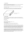
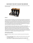
Orient3D is a 3-axis magnetic field sensing module. It uses three orthogonally placed magnetoinductive sensors to detect the earth's magnetic field.
With the data retrieved from an Orient3D, heading, pitch and roll can be computed.
The Orient3D can be used in analog mode, which consists of three 0-5V outputs; or in digital
2
mode, through an I C bus.
2
When in digital mode, you can daisy-chain up to four Orient3Ds per microDig I C port.
2
Since each microdig allows for four I C ports, you could end up with sixteen Orient 3D.
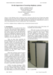
Z
Y
Orient3D internal X, Y and Z
sensor orientation
X
2 - How it works
Inside the Orient3D, each axis sensor outputs a 2´s complement, 16bit integer (ranging from
32767 to -32768) depending on the magnetic field strength and of the axis orientation respect to
the magnetic field lines.
Mathematically:
Sn = M * G * cos(θ)
Where Sn is the sensor output (n is either x, y or z)
M is the magnetic field strength
G is the sensor gain
θ is the angle between the sensor’s axis and the magnetic field lines.
The gain might be scaled by a factor: 1/64, 1/32, 1/16, 1/8, 1/4, 1/2, 1, 2
Gain is defined as the change in the number of counts from the sensor, when the scaling factor
is 1, per change in the magnetic field in µT (G=31.24 Count/µT, see specifications section). For
situations requiring higher gain and less field measurement range, the gain (and resolution) can
be increased by a factor of 2, then G = 2*31.24 = 62.48 Count/µT. For smaller gains, or when
saturation occurs, the scaling factor should be set to smaller a value. Be aware that the counter
can overflow if the field is strong enough drive the count beyond a signed 16-bit integer.
Internally each sensor is part of an oscillator whose frequency varies according to the magnetic
field parallel to the sensor’s axis. This oscillator frequency is fed into a period counter, after
being divided by a user-specified divisor. The available divisor ratios are: 32, 64, 128, 256, 512,
1024, 2048 and 4096. The output from the Orient3D is the count, so the divisor is effectively the
gain scaling factor. A higher divisor corresponds to a longer period, a greater high speed
oscillator count (the output) and better resolution.
2
In I C mode, Orient3D will return a copy of each sensor’s output Sx, Sy and Sz (three integers).
This mode is very useful for direction, pitch and roll angle computing:
Heading = arctan( Sx / Sy )
Pitch = arctan( Sx / Sz )
Roll = arctan( Sy / Sz )
In analog mode, Orient3D will output three 0-5V analog signals (one per axis) based on the 10
least significant bits of above integers.
Doing the math:
An = 5V * (Sn’ + 512) / 1024
Where An is the analog output and
− 512 if
Sn' = Sn
if
511 if
Sn < −512
− 512 ≤ Sn ≤ 511
Sn > 511
Note: If the analog outputs get saturated you should scale down the gain.
3 - Examples
Note 1: These examples illustrate the behaviour of the x axis only; in practice for each
orientation all three axes could be computed.
Note 2: The strength of the field at the Earth's surface ranges from less than 30 microteslas (0.3
gauss) in an area including most of South America and South Africa to over 60 microteslas (0.6
gauss) around the magnetic poles in northern Canada and south of Australia, and in part of
Siberia (Wikipedia)
Example 1: M = 15µT, G=31.24 Count/µT
1.1) θ = 0º (X sensor’s axis is aligned to the magnetic field lines)
Sx = M*G*cos(θ) = 15µT * 31.24 Count/µT * cos(0º) = 468 (=0X01D4)
Ax = 5V * (Sx’ + 512) / 1024 = 5V * (468 + 512) / 1024 = 4.785V
1.2) θ = 60º
Sx = M*G*cos(θ) = 15µT * 31.24 Count/µT * cos(60º) = 234 (=0X00EA)
Ax = 5V * (Sx’ + 512) / 1024 = 5V * (234 + 512) / 1024 = 3.643V
1.3) θ = 90º (X sensor’s axis perpendicular to the magnetic field lines)
Sx = M*G*cos(θ) = 15µT * 31.24 Count/µT * cos(90º) = 0 (=0X0000)
Ax = 5V * (Sx’ + 512) / 1024 = 5V * (0 + 512) / 1024 = 2.5V
1.4) θ = 120º
Sx = M*G*cos(θ) = 15µT * 31.24 Count/µT * cos(120º) = -234 (=0XFF16)
Ax = 5V * (Sx’ + 512) / 1024 = 5V * (-234 + 512) / 1024 = 1.357V
1.5) θ = 180º (X sensor’s axis is aligned to the magnetic field lines but in opposite direction)
Sx = M*G*cos(θ) = 15µT * 31.24 Count/µT * cos(180º) = -468 (=0XFE2C)
Ax = 5V * (Sx’ + 512) / 1024 = 5V * (-468 + 512) / 1024 = 0.215V
Example 2: M=30µT, G=62.48 Count/uT
2.1) θ = 60º
Sx = M*G*cos(θ) = 30µT * 62.48 Count/µT * cos(60º) = 937 (=0X03A9)
Ax = 5V * (Sx’ + 512) / 1024 = 5V * (511 + 512) / 1024 = 4.995V (saturated)
Example 3: M=30µT, G=15.62 Count/µT
3.1) θ = 60º
Sx = M*G*cos(θ) = 30µT * 15.62 Count/µT * cos(60º) = 234 (=0X00EA)
Ax = 5V * (Sx’ + 512) / 1024 = 5V * (234 + 512) / 1024 = 3.643V
4 - Hardware description
4.1- Hack cable male connectors
2
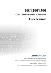
The Orient3D is powered through the 3D (3-channel) Hack cable. In I C mode, only the first two
channels are needed. For analog mode, all three are needed.
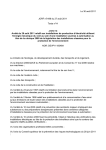
4-pin male connector
2
Pin assignment in I C mode:
1- power
red
5V, 7mA per Orient3D connected in daisy chain
2- i2c_data
black input/output, open drain, Rpullup=4k7
3- i2c_clock
white input/output, open drain, Rpullup=4k7
4- ground
shield 0V
Pin assignment in analog mode:
1- power
red
5V, 7mA
2- analog_x
black output 0-5V, Rout=2k2
3- analog_y
white output 0-5V, Rout=2k2
4- ground
shield 0V
4
3
Hack cable, 4-pin
male connector.
Front view
1
2
1-pin male connector
2
Pin assignment in I C mode:
1- aux
grey
output, 100ms positive pulse if any axis changes more then the
2
amount set with the I C command: SET DELTA
Pins assignment in analog mode:
1- analog_z
grey
output 0-5V, Rout=2k2
Hack cable, 1-pin
male connector.
Front view
1
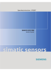
4.2 - Daisy chain female connector
2
This connector is only used in I C mode and allows for daisy chaining up to four Orient3D
sensors.
Pins assignment:
1- power
2- i2c_data
3- i2c_clock
4- ground
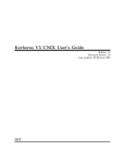
Daisy Chain
1
2
4
3
Dip Switch
1
Orient 3D lateral view
2
3
On
4.3 - Dip switch functions
2
Switches 1 and 2 in I C mode:
2
I C address bits 1 and 0 (the two address less significant bits)
1:off / 2:off
address = xxxxx00
1:off / 2:on
address = xxxxx01
1:on / 2:off
address = xxxxx10
1:on / 2:on
address = xxxxx11
2
(Where xxxxx are the five most significant bits; these may be change with the I C
command: SET ADDRESS)
Switches 1 and 2 in analog mode:
2
Gain scale factor (In I C mode the scale factor is changed with a command)
1:off / 2:off
scale factor = 1/4
1:off / 2:on
scale factor = 1/2
1:on / 2:off
scale factor = 1
1:on / 2:on
scale factor = 2
Switch 3
Mode select:
3:on
3:off
analog mode
2
I C mode
5 - I2C setup
2
2
If you are unfamiliar with the microdig’s I C commands, look up the host mode commands: “I C
2
2
PORT SET”, “I C WRITE” and “I C READ” in the document “Wi-microdig communication
protocol.pdf”, before continuing.
2
1 - Set dip switch 3 to the off position; I C mode.
2
2 - Set dip switches 1 and 2 with the I C's address least significant bits. The five more significant
bits need to be known in order to be able to send a command to the Orient3D, if you don't know
which is this address, follow the next procedure to clear these five bits:
a- Turn off the Orient3D and set dip switch 3 to the on position (analog mode)
b- Turn on the Orient3D, the address five more significant bits are now 00000.
2
c- Turn off the Orient3D and set dip switch 3 to the off position (I C mode)
2
3 - Plug the hack cable 4-pin male connector (power & I C bus) to the microdig.
4 - If desired plug the hack cable 1-pin male connector (aux signal) to the microdig.
5 - If desired, daisy chain three more Orient3D by plugging the hack cable 4-pin male connector
2
(power & I C bus) of the second Orient3D into the female daisy chain connector of the first
Orient3D. The aux signal can not be used in the daisy chained Orient3Ds.
The daisy chained Orient3Ds should have different addresses.
6 - Power up the microdig.
7 - Reset the microdig.
8 - Set the microdig in host mode.
2
9 - Configure/select the microdig ports where the I C bus has been plugged with the command
2
2
“I C PORT SET”. This command should be sent each time you want to use a different I C port
2
before sending any command to the Orient3Ds in that I C bus.
Note: The data returned by the Orient3D may need to be calibrated to the working location /
environment. This should be done by the system processing the data.
The available Max/MSP patch includes a calibration procedure. See the I-cubeX web page.
Also see “Calibration.pdf” for more details on calibration.
6 - Orient3D I2C commands
2
If you are using a microdig as I C master, the following commands should be sent /
2
2
encapsulated with the “I C WRITE” and “I C READ” commands.
2
The Orient3D I C commands have a “get or set register” form. The register’s size may vary
according to the data stored in it.
2
6.1 - I C Command: GET XYZ (read register 0, whose size is 6 bytes)
The data received are the three X, Y and Z, 2’s complement 16 bit integers.
Example (dec):
Send: 240, 125, 0 {DEV}, 127 {I2C READ}, 0 {address of I2C device}, 0, 0 {register 16*0+0=0}, 6 {bytes to be read},
247
Receive: 240, 125, 0 {DEV}, 127 {I2C READ}, 0 {address of I2C device}, 0, 0 {register 16*0+0=0}, 6 {bytes to be read},
1, 2, 3, 4 {X=1234h=4660}, 15, 14, 13, 12 {Y=FEDCh=-292}, 5, 6, 7, 8 {Z=5678h=22136}, 247
Example (hex):
Send: F0h, 7Dh, 00h {DEV}, 7Fh {I2C READ}, 00h {address of I2C device}, 00h, 00h {register 16*0+0=0}, 06h {bytes to
be read}, F7h
Receive: F0h, 7Dh, 00h {DEV}, 7Fh {I2C READ}, 00h {address of I2C device}, 00h, 00h {register 16*0+0=0}, 06h
{bytes to be read}, 01h, 02h, 03h, 04h {X=1234h}, 0Fh, 0Eh, 0Dh, 0Ch {Y=FEDCh}, 05h, 06h, 07h, 08h {Z=5678h}, F7h
2
6.2 - I C Command: GET VERSION (read register 1, whose size is 2 bytes)
The first byte received is the hardware release; the second byte is the software release.
Example (dec):
Send: 240, 125, 0 {DEV}, 127 {I2C READ}, 0 {address of I2C device}, 0, 1 {register 16*0+1=1}, 2 {bytes to be read},
247
Receive: 240, 125, 0 {DEV}, 127 {I2C READ}, 0 {address of I2C device}, 0, 1 {register 16*0+1=1}, 2 {bytes to be read},
0, 1 {HW rel =16*0+1=1}, 0, 1 {SW rel=16*0+1=1}, 247
Example (hex):
Send: F0h, 7Dh, 00h {DEV}, 7Fh {I2C READ}, 00h {address of I2C device}, 00h, 01h {register 16*0+1=1}, 02h {bytes to
be read}, F7h
Receive: F0h, 7Dh, 00h {DEV}, 7Fh {I2C READ}, 00h {address of I2C device}, 00h, 01h {register 16*0+1=1}, 02h
{bytes to be read}, 00h, 01h {HW rel = 01h}, 00h, 01h {SW rel = 01h}, F7h
2
6.3 - I C Command: SET GAIN SCALING FACTOR (write register 2, whose size is 1 byte)
2
The value written into this register will be the gain scaling factor when working in I C mode.
The range should be in between 0 to 7 (00h to 07h). The gain scale factor will be stored into a
non volatile memory. The value received will be masked (and’ed) with 0X07, so if the value is
out of range, only the three least significant bits will remain.
Byte received [ x x x x x F3 F1 F0 ] & Mask [ 0 0 0 0 0 1 1 1 ] = [ 0 0 0 0 0 F3 F1 F0]
Example (dec):
Send: 240, 125, 0 {DEV}, 126 {I2C WRITE}, 0 {address of I2C device}, 0, 2 {register 16*0+2=2}, 0, 7 {SCALE
FAC=16*0+7=7}, 247
Receive: (echo of the sent data)
Example (hex):
Send: F0h, 7Dh, 00h {DEV}, 7Eh {I2C WRITE}, 00h {address of I2C device}, 00h, 02h {register 16*0+2=2}, 00h, 07h
{SCALE FAC=07h}, F7h
Receive: (echo of the sent data)
2
6.4 - I C Command: SET ADDRESS (write register 3, whose size is 1 byte)
2
This byte sets the five most significant bits of the I C address. The value received will be
masked (ANDed) with 0X7C; then if the value is out of range, the byte most significant bit and
two least bits will be 0. This part of the address will be stored in non volatile memory
Byte received [ x A7 A6 A5 A4 A3 x x ] & Mask [ 0 1 1 1 1 1 0 0 ] = [ 0 A7 A6 A5 A4 A3 0 0 ]
2
The final I C address is this result ORed with the values of dip switches 1 and 2.
Address = [ 0 A7 A6 A5 A4 A3 0 0 ] | [ 0 0 0 0 0 0 SW1 SW2 ] = [ 0 A7 A6 A5 A4 A3 SW1 SW2 ]
2
This I C command is only available if it's the first command after power up, thus preventing any
2
unwanted I C address changes. You can keep sending this command as long as no other
command is send in between.
Note: If this value is unknown or forgotten you won’t be able to communicate by the device,
2
follow the procedure in the “I C setup” section to set these bits to 0.
Example (dec):
Send: 240, 125, 0 {DEV}, 126 {I2C WRITE}, 0 {address of I2C device}, 0, 3 {register 16*0+3=3}, 1, 0
{ADDRESS=16*1+0=16}, 247
Receive: (echo of the sent data)
Example (hex):
Send: F0h, 7Dh, 00h {DEV}, 7Eh {I2C WRITE}, 00h {address of I2C device}, 00h, 03h {register 16*0+3=3}, 01h, 00h
{ADDRESS=10h}, F7h
Receive: (echo of the sent data)
2
6.5 - I C Command: SET DELTA (write register 4, whose size is 1 byte)
When any of the axes changes more then the amount written into this register, a 100ms positive
pulse will be generated at the aux pin. The range should be in between 0 to 255 (00h to FFh).
The delta value will be stored in non volatile memory.
Every time a new axis is sensed, the new value is compared to the axis’s latched value +/- the
delta amount. If the new value is greater, the latch is updated and a pulse is generated in the
aux pin.
2
This function could be useful to avoid constant I C requests to the sensor if there is no
significant change detected by the Orient3D. This results in less data traffic for the microdig and
thus less power used for transmission.
For example (delta = 10; initial X,Y,Z latched values = 0)
t
X
Y
Z
aux
-----------------------------------------------------------1
0
0
-127
trigger; Z<(Z latched - 10); new Z latched = –127
2
3
2
-123
no trigger
3
5
2
-118
no trigger
4
8
3
-115
trigger; Z>(Z latched + 10); new Z latched = –115
5
11
2
-115
trigger; X>(X latched + 10); new X latched = 11
6
12
1
-116
no trigger
Example (dec):
Send: 240, 125, 0 {DEV}, 126 {I2C WRITE}, 0 {address of I2C device}, 0, 4 {register 16*0+4=4}, 8, 4 {DELTA
=16*8+4=132}, 247
Receive: (echo of the sent data)
Example (hex):
Send: F0h, 7Dh, 00h {DEV}, 7Eh {I2C WRITE}, 00h {address of I2C device}, 00h, 04h {register 16*0+4=4}, 08h, 04h
{DELTA =84h}, F7h
Receive: (echo of the sent data)
2
6.6 - I C Command: SET LED (write register 5, whose size is 1 byte)
2
Enable or disable the LED for I C command: GET XYZ . Write 0 (00h) to enable the LED or
write any other value to disable it. This value is not stored in non volatile memory. If the power is
cycled, the register value will be 0. The range should be in between 0 to 255 (00h to FFh).
Example (dec):
Send: 240, 125, 0 {DEV}, 126 {I2C WRITE}, 0 {address of I2C device}, 0, 5 {register 16*0+5=5}, 0, 1 {LED =16*0+1=1},
247
Receive: (echo of the sent data)
Example (hex):
Send: F0h, 7Dh, 00h {DEV}, 7Eh {I2C WRITE}, 00h {address of I2C device}, 00h, 05h {register 16*0+5=5}, 00h, 01h
{LED =01h}, F7h
Receive: (echo of the sent data)
7 - Analog setup
1 - Set dip switch 3 to the on position; analog mode (Please note that after doing this and
2
powering the sensor, the five most significant bits of the I C address will be set to 00000)
2 - Set dip switches 1 and 2 with the desired gain scaling factor (this can be done at any time)
3 - Plug the hack cable 4-pin male connector (x & y) to the microdig.
4 - Plug the hack cable 1-pin male connector (z) to the microdig.
5 - Power up the microdig.
6 - Reset the microdig.
7 - Set the microdig in stand alone mode.
8 - Configure the microdig ports as analog inputs with the desired resolution. Use Pitch Bend for
12-bit resolution.
8- Analog calibration
The following describes using the editor to calibrate the microDig to give a full-scale reading for
each axis.
Set the scale factor dip switches to the highest value (2)
Repeat the following procedure for all three axes.
1 - Align the sensor’s axis to the north, keeping it tangent to the earth surface (ie horizontally
flat), looking for the maximum reading (the closest to 5V), if the reading gets saturated scale
down the gain with the dip switches. If necessary invert the signal.
2- Without changing the direction away from north, adjust the sensor’s axis pitch, looking for the
maximum reading (the closest to 5V), if the reading gets saturated scale down the gain with the
dip switches.
3- The sensor is now aligned to the earth’s magnetic lines.
4- Without moving the Orient3D set the high threshold to get the maximum reading.
5- Align the sensor axis to the south, looking for the minimum reading (the closest to 0V), if the
reading gets saturated scale down the gain with the dip switches.
6- Without moving the Orient3D set the low threshold to get the minimum reading.
Now, you will get a value from 0 to 127 (0 to 16383 in high resolution) for each Orient3D axis
according to their orientation in the earth magnetic field lines.
You can also do this in the Max/MSP patch from the website. If you are using the patch, then
simply use the editor to set the microdig to standalone mode, and enable 3 inputs and set each
one to output pitch-bend messages (0 – 16383).
9 - Specifications
Sensors Parameters
Measurement range
Accuracy
Gain
Scale factor = 1
Scale factor = 2
Resolution
Linearity (Error from best fit straight line at ±300 uT)
Electrical Parameters
Supply voltage
Supply Current
2
I C input, high voltage threshold
2
I C input, low voltage threshold
2
I C pullup resistors
2
I C output, low voltage level (Io 20mA)
2
I C output, sink current (Vo 0.7V)
Analog output, voltage range
Analog output, DC equivalent resistance
Timing
2
I C clock frequency
2
I C inter command time
Analog output, response time (10 to 90%)
Internal three axis sensors sample time
Scale factor = 2
Scale factor = 1
Scale factor = 1/2
Scale factor = 1/4
Scale factor = 1/8
Scale factor = 1/16
Scale factor = 1/32
Scale factor = 1/64
min
-1100µT
typical
max
+1100µT
0.015µT
31.24 Count/µT
62.48 Count/µT
1/Gain µT
0.6%
min
4.75V
7mA
3V
-0.5V
typical
5V
8mA
1%
max
5.25V
9mA
5.25V
1.5V
4K7 ohm
0.7V
20mA
5V
0V
2K2 ohm
min
typical
max
50kHz
10ms
50ms
180ms
106.5ms
45ms
22.50ms
12ms
6ms
3ms
1.5ms