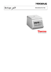
1
Operating instructions Hot-Air Disinfectable Gassed Incubator BBD 6220 Read this operating instructions and keep it near the equipment for reference purposes ! Valid: 03.2006 / 50 079 041 A Postal adress Germany Thermo Electron LED GmbH Robert-Bosch-Straße 1 D - 63505 Langenselbold Postal address USA Thermo Electron Corporation 275 Aiken Road Asheville, NC 28804 USA Enquiries from Germany Phone Sale 0800 1 536376 Service 0800 1 112110 Fax Sale/Service 0800 1 112114 E-Mail [email protected] Enquiries from North America Phone +1 800-879 7767 Fax +1 828-658 0363 E-Mail [email protected] Enquiries from Europe, Middle East and Africa Tel. + 49 (0) 6184 / 90-6940 Fax + 49 (0) 6184 / 90-7474 E-Mail [email protected] Enquiries from Latin America Phone +1 828-658 2711 Fax +1 828-645 9466 E-Mail [email protected] Enquiries from Asia Pacific Phone +852-2711 3910 Fax +852-2711 3858 E-Mail [email protected] Copyright © Thermo Electron GmbH, D-63505 Langenselbold, Deutschland No part of this publication may be reproduced or transmitted in any form or by any means, including photocopying and recording, without the written permission of Thermo Electron GmbH. Various sections of this instruction manual may be copied only for in-house use by the equipment operator, e.g. to provide employees with instructions on accident prevention measures. These sections are clearly marked in the list of contents. Thermo Electron GmbH can accept no liability or responsibility for the marketability or the suitability of this instruction manual for a certain purpose other than that specified under "Areas of application of equipment". Thermo Electron GmbH reserves the right to change the content of this instruction manual at any time and without prior notice. As regards foreign-language translations, the German version of this instruction manual is binding. This edition of the instruction manual applies to the BBD 6220 unit specified on the front page. Date of publication: 03.2006 Nominal charge Safety with regard to the protection of persons, the environment and the material under process largely depends on the conduct of the persons using the equipment. This instruction manual is important for your safety as well as for the setup, installation, use and maintenance of the equipment! To avoid errors and any resulting damage, especially personal injuries, be sure to read this manual carefully before using the equipment and follow all instructions. 2/43 50 079 041 LIST OF CONTENTS PAGE 1. GENERAL . . . . . . . . . . . . . . . . . . . . . . . . . . . . . . . . . . . . . . . . . . . . . . . . . . . . . . . . . . . . . . . . . . . . . . . . . . . . . . . . 5/7 Explanation of icons in the instructions manual . . . . . . . . . . . . . . . . . . . . . . . . . . . . . . . . . . . . . . . . . . . . . . . . . . . . . 5 Explanation of icons in the short instructions . . . . . . . . . . . . . . . . . . . . . . . . . . . . . . . . . . . . . . . . . . . . . . . . . . . . . . . 6 General instructions . . . . . . . . . . . . . . . . . . . . . . . . . . . . . . . . . . . . . . . . . . . . . . . . . . . . . . . . . . . . . . . . . . . . . . . . . . . . . . . 7 Equipment log book . . . . . . . . . . . . . . . . . . . . . . . . . . . . . . . . . . . . . . . . . . . . . . . . . . . . . . . . . . . . . . . . . . . . . . . . . . . . . . . 7 Operating instructions . . . . . . . . . . . . . . . . . . . . . . . . . . . . . . . . . . . . . . . . . . . . . . . . . . . . . . . . . . . . . . . . . . . . . . . . . . . . . 7 2. AREAS OF APPLICATION . . . . . . . . . . . . . . . . . . . . . . . . . . . . . . . . . . . . . . . . . . . . . . . . . . . . . . . . . . . . . . . . . . . 8 3. SAFETY INSTRUCTIONS . . . . . . . . . . . . . . . . . . . . . . . . . . . . . . . . . . . . . . . . . . . . . . . . . . . . . . . . . . . . . . . . . . . . 9 4. SETUP AND INSTALLATION . . . . . . . . . . . . . . . . . . . . . . . . . . . . . . . . . . . . . . . . . . . . . . . . . . . . . . . . . . . . 10-12 Transport . . . . . . . . . . . . . . . . . . . . . . . . . . . . . . . . . . . . . . . . . . . . . . . . . . . . . . . . . . . . . . . . . . . . . . . . . . . . . . . . . . . . . . . . . 10 Place of installation . . . . . . . . . . . . . . . . . . . . . . . . . . . . . . . . . . . . . . . . . . . . . . . . . . . . . . . . . . . . . . . . . . . . . . . . . . . . . . 10 Stacking . . . . . . . . . . . . . . . . . . . . . . . . . . . . . . . . . . . . . . . . . . . . . . . . . . . . . . . . . . . . . . . . . . . . . . . . . . . . . . . . . . . . . . . . . . 10 Clearances . . . . . . . . . . . . . . . . . . . . . . . . . . . . . . . . . . . . . . . . . . . . . . . . . . . . . . . . . . . . . . . . . . . . . . . . . . . . . . . . . . . . . . . 11 Supply connections . . . . . . . . . . . . . . . . . . . . . . . . . . . . . . . . . . . . . . . . . . . . . . . . . . . . . . . . . . . . . . . . . . . . . . . . . . . . . . . 11 Mains connection . . . . . . . . . . . . . . . . . . . . . . . . . . . . . . . . . . . . . . . . . . . . . . . . . . . . . . . . . . . . . . . . . . . . . . . . . . . . . . . . . 11 Gas supply connection . . . . . . . . . . . . . . . . . . . . . . . . . . . . . . . . . . . . . . . . . . . . . . . . . . . . . . . . . . . . . . . . . . . . . . . . . . . . 12 RS 232 interface . . . . . . . . . . . . . . . . . . . . . . . . . . . . . . . . . . . . . . . . . . . . . . . . . . . . . . . . . . . . . . . . . . . . . . . . . . . . . . . . . 12 "Potential-free contact" connection . . . . . . . . . . . . . . . . . . . . . . . . . . . . . . . . . . . . . . . . . . . . . . . . . . . . . . . . . . . . . . . . 12 5. DESCRIPTION OF THE UNIT . . . . . . . . . . . . . . . . . . . . . . . . . . . . . . . . . . . . . . . . . . . . . . . . . . . . . . . . . . . . 13/14 Levelling the shelves . . . . . . . . . . . . . . . . . . . . . . . . . . . . . . . . . . . . . . . . . . . . . . . . . . . . . . . . . . . . . . . . . . . . . . . . . . . . . 13 Functional principle . . . . . . . . . . . . . . . . . . . . . . . . . . . . . . . . . . . . . . . . . . . . . . . . . . . . . . . . . . . . . . . . . . . . . . . . . . . . . . . 13 Heating system . . . . . . . . . . . . . . . . . . . . . . . . . . . . . . . . . . . . . . . . . . . . . . . . . . . . . . . . . . . . . . . . . . . . . . . . . . . . . . . . . . . 13 Gassing . . . . . . . . . . . . . . . . . . . . . . . . . . . . . . . . . . . . . . . . . . . . . . . . . . . . . . . . . . . . . . . . . . . . . . . . . . . . . . . . . . . . . . . . . . 13 Humidification . . . . . . . . . . . . . . . . . . . . . . . . . . . . . . . . . . . . . . . . . . . . . . . . . . . . . . . . . . . . . . . . . . . . . . . . . . . . . . . . . . . . 14 Door switch . . . . . . . . . . . . . . . . . . . . . . . . . . . . . . . . . . . . . . . . . . . . . . . . . . . . . . . . . . . . . . . . . . . . . . . . . . . . . . . . . . . . . . . 14 Internal fittings . . . . . . . . . . . . . . . . . . . . . . . . . . . . . . . . . . . . . . . . . . . . . . . . . . . . . . . . . . . . . . . . . . . . . . . . . . . . . . . . . . . . 14 Six-piece Gas-tight glass screen . . . . . . . . . . . . . . . . . . . . . . . . . . . . . . . . . . . . . . . . . . . . . . . . . . . . . . . . . . . . . . . . . 14 Lockable outside door . . . . . . . . . . . . . . . . . . . . . . . . . . . . . . . . . . . . . . . . . . . . . . . . . . . . . . . . . . . . . . . . . . . . . . . . . . . . 14 Disinfection routine . . . . . . . . . . . . . . . . . . . . . . . . . . . . . . . . . . . . . . . . . . . . . . . . . . . . . . . . . . . . . . . . . . . . . . . . . . . . . . . 14 "Potential-free contact" connection . . . . . . . . . . . . . . . . . . . . . . . . . . . . . . . . . . . . . . . . . . . . . . . . . . . . . . . . . . . . . . . . 14 6. OPERATE . . . . . . . . . . . . . . . . . . . . . . . . . . . . . . . . . . . . . . . . . . . . . . . . . . . . . . . . . . . . . . . . . . . . . . . . . . . . . . 15-30 Switch panel . . . . . . . . . . . . . . . . . . . . . . . . . . . . . . . . . . . . . . . . . . . . . . . . . . . . . . . . . . . . . . . . . . . . . . . . . . . . . . . . . . . . . . 15 Water supply . . . . . . . . . . . . . . . . . . . . . . . . . . . . . . . . . . . . . . . . . . . . . . . . . . . . . . . . . . . . . . . . . . . . . . . . . . . . . . . . . . . . . 16 Mains switch . . . . . . . . . . . . . . . . . . . . . . . . . . . . . . . . . . . . . . . . . . . . . . . . . . . . . . . . . . . . . . . . . . . . . . . . . . . . . . . . . . . . . 16 Temperature protection device (temperature limit controller) . . . . . . . . . . . . . . . . . . . . . . . . . . . . . . . . . . . . . . . 18 Control and display panels . . . . . . . . . . . . . . . . . . . . . . . . . . . . . . . . . . . . . . . . . . . . . . . . . . . . . . . . . . . . . . . . . . . . 18-21 Disinfection routine . . . . . . . . . . . . . . . . . . . . . . . . . . . . . . . . . . . . . . . . . . . . . . . . . . . . . . . . . . . . . . . . . . . . . . . . . . . . 21/22 auto-start routine / auto-zero routine . . . . . . . . . . . . . . . . . . . . . . . . . . . . . . . . . . . . . . . . . . . . . . . . . . . . . . . . . . . 23/24 Error code enquiry . . . . . . . . . . . . . . . . . . . . . . . . . . . . . . . . . . . . . . . . . . . . . . . . . . . . . . . . . . . . . . . . . . . . . . . . . . . . 23/25 Switching functions . . . . . . . . . . . . . . . . . . . . . . . . . . . . . . . . . . . . . . . . . . . . . . . . . . . . . . . . . . . . . . . . . . . . . . . . . . . . . . . 27 Switching function: Acoustic alarm ON/OFF . . . . . . . . . . . . . . . . . . . . . . . . . . . . . . . . . . . . . . . . . . . . . . . . . . . . . . . 27 Switching function: Humidification ON/OFF . . . . . . . . . . . . . . . . . . . . . . . . . . . . . . . . . . . . . . . . . . . . . . . . . . . . . . . . 28 Switching function: Manual zero calibration of CO2 measuring system . . . . . . . . . . . . . . . . . . . . . . . . . . . . . 29 Switching function: Setpoint lock-in ON/OFF . . . . . . . . . . . . . . . . . . . . . . . . . . . . . . . . . . . . . . . . . . . . . . . . . . . . . . 30 Switching function: Door heater ON/OFF . . . . . . . . . . . . . . . . . . . . . . . . . . . . . . . . . . . . . . . . . . . . . . . . . . . . . . . . . . 31 50 079 041 3/45 LIST OF CONTENTS PAGE 7. START-UP . . . . . . . . . . . . . . . . . . . . . . . . . . . . . . . . . . . . . . . . . . . . . . . . . . . . . . . . . . . . . . . . . . . . . . . . . . . . . . . . . . . . 32 8. OPERATION . . . . . . . . . . . . . . . . . . . . . . . . . . . . . . . . . . . . . . . . . . . . . . . . . . . . . . . . . . . . . . . . . . . . . . . . . . . . . . . . . . Guidelines for use . . . . . . . . . . . . . . . . . . . . . . . . . . . . . . . . . . . . . . . . . . . . . . . . . . . . . . . . . . . . . . . . . . . . . . . . . . . . . . . . . . . Before putting the unit into operation . . . . . . . . . . . . . . . . . . . . . . . . . . . . . . . . . . . . . . . . . . . . . . . . . . . . . . . . . . . . . . . . . During operation . . . . . . . . . . . . . . . . . . . . . . . . . . . . . . . . . . . . . . . . . . . . . . . . . . . . . . . . . . . . . . . . . . . . . . . . . . . . . . . . . . . . . Operation interruptions . . . . . . . . . . . . . . . . . . . . . . . . . . . . . . . . . . . . . . . . . . . . . . . . . . . . . . . . . . . . . . . . . . . . . . . . . . . . . . 9. SHUTDOWN 33 33 33 33 33 . . . . . . . . . . . . . . . . . . . . . . . . . . . . . . . . . . . . . . . . . . . . . . . . . . . . . . . . . . . . . . . . . . . . . . . . . . . . . . . . . 34 10. MAINTENANCE . . . . . . . . . . . . . . . . . . . . . . . . . . . . . . . . . . . . . . . . . . . . . . . . . . . . . . . . . . . . . . . . . . . . . . . . . . . . 35/36 Cleaning/Disinfection . . . . . . . . . . . . . . . . . . . . . . . . . . . . . . . . . . . . . . . . . . . . . . . . . . . . . . . . . . . . . . . . . . . . . . . . . . . . . . . . 35 Testing . . . . . . . . . . . . . . . . . . . . . . . . . . . . . . . . . . . . . . . . . . . . . . . . . . . . . . . . . . . . . . . . . . . . . . . . . . . . . . . . . . . . . . . . . . . . . 36 Equipment log book . . . . . . . . . . . . . . . . . . . . . . . . . . . . . . . . . . . . . . . . . . . . . . . . . . . . . . . . . . . . . . . . . . . . . . . . . . . . . . . . . 36 Replacing of electrical parts . . . . . . . . . . . . . . . . . . . . . . . . . . . . . . . . . . . . . . . . . . . . . . . . . . . . . . . . . . . . . . . . . . . . . . . . . . 36 11. AUTHORIZED EQUIPMENT PARTS AND ACCESSORIES . . . . . . . . . . . . . . . . . . . . . . . . . . . . . . . . . . . . . . . 37 12. TECHNICAL SPECIFICATIONS . . . . . . . . . . . . . . . . . . . . . . . . . . . . . . . . . . . . . . . . . . . . . . . . . . . . . . . . . . . . . 38/39 13. MATERIALS USED / DISPOSAL . . . . . . . . . . . . . . . . . . . . . . . . . . . . . . . . . . . . . . . . . . . . . . . . . . . . . . . . . . . . . . . 40 14. GAS CONSUMPTION . . . . . . . . . . . . . . . . . . . . . . . . . . . . . . . . . . . . . . . . . . . . . . . . . . . . . . . . . . . . . . . . . . . . . . . . . 41 15. PH-VALUE OF CULTURE MEDIA . . . . . . . . . . . . . . . . . . . . . . . . . . . . . . . . . . . . . . . . . . . . . . . . . . . . . . . . . . . . . . 42 Basic rules of sound microbiological engineering practice . . . . . . . . . . . . . . . . . . . . . . . . . . . . . . . . . 43/44 General rules . . . . . . . . . . . . . . . . . . . . . . . . . . . . . . . . . . . . . . . . . . . . . . . . . . . . . . . . . . . . . . . . . . . . . . . . . . . . . . . . . . . . . . . . 43 Handling of pathogenes . . . . . . . . . . . . . . . . . . . . . . . . . . . . . . . . . . . . . . . . . . . . . . . . . . . . . . . . . . . . . . . . . . . . . . . . . . 43/44 Handling of human- and animal-pathogenic biological agents . . . . . . . . . . . . . . . . . . . . . . . . . . . . . . . . . . . . . . . . . 44 APPENDIX Statement of conformity Log Book Explanation of confirmation of safety Information request form regarding maintenance and servicing contract Communication-protocol of RS 232-device 4/43 50 079 041 1. GENERAL EXPLANATION OF ICONS IN THE INSTRUCTIONS MANUAL In chapters of the instruction manual which deal with safety, this icon appears under the title of the chapter. Displayed on the equipment, this icon denotes that special attention must be paid to the information given in the instruction manual or accompanying documents. Marks information in the instruction manual for optimizing use of the equipment "Water supply" vent/overflow "Add/drain water" quick release coupling aqua dest I 0 des start/ stop "des" Unit ON Unit OFF "Disinfection mode" key-operated switch Marks information for higher surface temperature in the disinfection mode Overtemperature protection, temperature limit controller Selection of switching/interlocking functions i control Error code enquiry / acknowledgment of "acoustic signal" "Change switching functions activated" display auto-start Automatic startup of unit and calibration of measuring systems auto-zero "auto-zero" calibration active display des "Disinfection mode" display Information on proper disposal / recovery of raw materials 50 079 041 5/45 1. GENERAL EXPLANATION OF ICONS TO THE SHORT INSTRUCTIONS 0 Switch on unit (operate the main switch) I max. aqua dest. Check the water level min. > + 2 °C Set the temperature limit controller °C Close unit doors L & Read the operating instructions des start/ stop Start "disinfection routine" ≥ 1 sec auto-start automatical "auto-start" Open unit doors for at least 30 seconds ≥ 30 s & &2 Set the desired setpoints 2 U + auto-start "activate" the auto-start ≥ 5s & start / stop End of the auto-start, bring in the samples auto-start Take out the samples, open unit doors for at least 30 seconds > 30 s 180 °C Flow chart of disinfection routine t 6/43 50 079 041 1. GENERAL General instructions To avoid errors and causing damage, especially personal injuries, be sure to read this manual carefully before using the equipment, and follow all instructions. When setting up and operating the unit, be sure to comply with the instructions contained in this manual as well as all applicable laws, regulations and directives in your country (FRG: ZH 1/119, ZH 1/342, ZH 1/343, ZH 1/598). The unit meets the following safety requirements DIN 12880 Part 1/11.78 DIN VDE 0700 Part 1 (IEC 335-1; EN 60335-1/11.90) EN 61010 When you have an enquiry, order replacement parts or file a complaint, please state the data on the nameplate and, if applicable, the fault code. Equipment log book We advise you to keep an equipment log book. Keep a record of inspections and testing, calibration work and any major work carried out on the unit - such as maintenance, agents loaded, etc. - in this log book (refer to APPENDIX). Operating instructions The operator (employer) is expected to provide anyone who works on or with the equipment with written instructions, based on this instruction manual, for the tasks to be performed. These instructions should be easy to understand and in the language of the persons operating the equipment. This also applies to disinfecting and cleaning the unit (also refer to Chapter 10: Maintenance). 50 079 041 7/45 2. AREAS OF APPLICATION The BBD 6220 gassed incubator is an item of laboratory equipment for cell and tissue cultures and can be used to simulate the physiological environmental conditions of cells. The unit is generally suitable for setup and operation in the following areas: In laboratories for microbiological and biotechnological work. Medical and microbiological laboratories to DIN 58956. Central laboratories in clinics and hospitals. Laboratories operating at safety levels L1, L2 and L3. Only organisms which comply with the requirements for safety levels L1, L2 and L3 may be handled in the unit. The unit must be set up and operated in accordance with all applicable regulations in your country. (FRG: ZH 1/119, ZH 1/342, ZH 1/343, ZH 1/598) It is not permitted to handle gases or agents whose vapours are combustible or can form a hazardous, potentially explosive atmosphere when mixed with air. Be sure to comply with the applicable regulations in your country. (FRG: ZH 1/10) 8/43 50 079 041 3. SAFETY INSTRUCTIONS In the case of biological incubators, biological safety with regard to the protection of persons, its surroundings and the load is heavily dependent on the observance of the applicable regulations by the persons using the equipment. Even then, however, the possibility of hazards, especially health hazards, arising cannot be ruled out. The residual risk depends on the work performed in each individual case. To avoid errors and causing damage, especially personal injuries, be sure to carefully read this manual before putting the equipment into operation, and follow all instructions. Safe and reliable operation of the unit can only be guaranteed if the necessary inspections, maintenance and repair work are carried out by Heraeus Service Department personnel or by personnel authorized by our company. Gas is to be supplied to each unit by means of a pressure reducer with the inlet pressure set to between 0.8 and max. 1 bar. This setting must not be changed for safety reasons (FRG: ZH 1/119). The place of installation must be thoroughly ventilated in order to expel the gases escaping around the pressure relief valve to the outside. To maintain the temperature protection function, the functioning of the overtemperature protection device, temperatur limit controller must be checked at reasonable intervals. Only original replacement parts authorized by the manufacturer are to be used. Refer to the Appendix titled "BASIC RULES OF SOUND MICROBIOLOGICAL ENGINEERING PRACTICE". 50 079 041 9/45 4. SETUP AND INSTALLATION When setting up, installing and operating the unit, be sure to comply with all applicable regulations in your country. (FRG: ZH 1/119, ZH 1/342, ZH 1/343, ZH 1/598) Transport Handle the unit with care during transport. Do not lift up the unit by its door. Refer to TECHNICAL SPECIFICATIONS for weights and dimensions. Place of installation The place of installation must be dry and draught-free. The unit should not be placed or operated in recesses which cannot be ventilated. To avoid or at least minimize deviations from the technical specifications, the temperature at the place of installation must be in the range +18°C to +30°C. Set up the unit on a solid, non-flammable surface (laboratory tables, subframes). Make sure that the unit is in a stable and perfectly upright position. Do not cover or obstruct the fresh air or exhaust vents in the unit housing (please observe the minimum clearances - see page 11). CO2 are admitted into the gassed incubator. CO2 is a health risk hazard. The place of installation must therefore be well-ventilated. Gases discharged from the pressure relief valve must be safely expelled outside by means of the ventilation systems. It may be necessary to take special measures in order to ensure proper ventilation when several units are installed in the same room. For information on gas flow during operation, refer to the APPENDIX. Stacking The unit is not suitable for stacking when operated in the manner intended. 10/43 50 079 041 4. SETUP AND INSTALLATION Clearances When setting up the unit, the minimum clearances between the unit and adjacent surfaces and other units must be maintained. 100 300 Larger clearances are recommended to facilitate accessibility for installation and the supply connections. 150 100 Fig. 1: Minimum clearances in mm Supply connections Mains socket C02 gas connection 02/N2 gas connection (option) Label: supply connection Potential-free contact RS 232 interface Fig. 2: Supply connections (rear panel of unit) Mains connection Prior to connecting the unit to the mains, make sure that the power supply ratings match those stated on the nameplate. Your unit is equipped with a power supply cable with a grounding contact-type plug. Fuse protection required: Use a type G 16 circuit-break switch or a type T 16 A fusible cutout. Refer to the Chapter titled TECHNICAL SPECIFICATIONS for unit power consumption. 50 079 041 11/45 4. SETUP AND INSTALLATION Gas supply connection The gas connection are located on the back of the unit. The gas must be supplied to each unit via a pressure reducer with the inlet pressure set to between 0.8 and max. 1 bar. This setting must not be changed for safety reasons (FRG: ZH 1/119). The gases must have at least 99.5% purity. If several units are placed in the same room, special ventilation measures are required. CO2 gassing Connect the gas cylinder to the gas nozzle on the unit. O2 / N2 gassing (optional) If you intend to run the unit with an oxygen content above 21%, connect an oxygen cylinder. If you intend to run the unit with an oxygen content less than 21%, connect a nitrogen cylinder. To deactivate the oxygen control, set the nominal value to 21.0% (average oxygen content of ambient atmosphere). RS 232 interface Serial interface for computer-aided acquisition and documentation of critical operating parameters (temperature, CO2, relative humidity, error codes, etc.). The RS 232 interface can connect a single unit in combination with the "Kelvilog" software package, and can be expanded to connect 31 units with the "Netcontrol" hard- and software package. "Potential - free contact" connection The "Potential-free contact" (1 changeover contact) is rated for the following circuits: Circuit Voltage Fuse to be installed by customer Mains-operated circuits max. 250 V AC max. 6 A SELV / SELV - E - circuits (cf. VDE 0100 Part 410) 25/50 V AC 60/120 V DC max. 2/1 A max. 1/0.5 A L F1x T2A 3 1 2 H1x Kx S1x X Kx View X PE H2x Kx A1 1 1s 3 2 A2 N Fig. 3 : Application example of "Potential - free contact" connection 12/43 50 079 041 5. DESCRIPTION OF THE UNIT Levelling the shelves The shelves can be aligned with the aid of a spirit level with height-adjustable feet. Functional principle The atmosphere in the chamber can be regulated in relation to its temperature, CO2 concentration, O2 concentration (optional) and relative humidity. Heating system The temperature inside the unit can be regulated in the range of +7°C to +50°C, but must be at least +5°C (approx. +7°C for the O2 version) above the ambient temperature of the unit. Condensation on the glass door is largely prevented by heating the unit door. If the unit door is left open for a long period of time, however, condensation cannot be ruled out. The unit door heater can be switched off as required (refer to Chapter headed OPERATION). This enables the unit to be operated at high ambient temperatures or when the operating temperature is only supposed to exceed the ambient temperature by approx. +4°C. Example: Ambient temperature Operating temp. Heating of unit door +25°C +37°C ON +24°C +28°C OFF +32°C to +33°C +37°C OFF Gassing Connection to the gas supplies (CO2,, O2 or rather N2) are located on the rear panel of the incubator. The CO2 content of the atmosphere in the chamber can be regulated in the range 0% to 20%. The O2 concentration inside the unit can be regulated in the range 3% to 90% O2 by admitting N2 (< 21% O2) or O2 (> 21% O2). The sum of the nominal values for CO2 + O2 must not exceed 90%. Example: 10% CO2 + 80% O2 = 90% (possible) 20% CO2 + 80% O2 = 100% (impossible) Before entering the chamber, all gases pass through a filter where particles larger than 0.3 µm are retained. Filter efficiency is 99.998%. A fan integrated in the rear of the interior wall ensures that the gases and the incubator atmosphere are thoroughly mixed. The sensors for CO2, O2 (option) and relative humidity are also located on the rear panel of the interior wall. These sensors measure the parameters inside the unit and transmit corresponding signals to the closed-loop controller. A pressure compensation vent on the rear panel of unit avoids undesirable pressure build-up inside the unit during the admission of gases. The place of installation must be thoroughly ventilated in order to expel the gases escaping around pressure compensation vent. 50 079 041 13/45 5. DESCRIPTION OF THE UNIT Humidification The atmosphere in the chamber is humidified through the admission of steam generated in a aktiv humifier. Relative humidity (rH) can be regulated between 60% and 95%. To ensure reliable operation of the steam generator, only fill the reservoir with fully desalinated or distilled water! The capacity of the reservoir is approx. 4.7 ltr (difference between min. and max. levels: 2.2 ltr). Door switch The heating system, gas supply and humidifier are switched off when the unit door is opened. The unit door can only be closed when all glass doors are sealed properly. If the unit door is not properly closed while the unit is in operation, a visual alarm is given (all LEDs flashing). If the door is open for longer than 10 minutes, an acoustic alarm sounds when this monitoring function is activated by way of function level 1 (refer to Page 26). Internal fittings Pull-out shelves, with support brackets to prevent tilting, are arranged inside the units. The support can be offset in the carrier racks at intervals of 46 mm. Six-piece gas-tight glass screen By virtue of the small vent cross-section, unnecessary cooling and discharge of the atmosphere in the chamber is largely avoided when a glass door is opened of the six-piece gas-tight glass screen. Lockable outside door The outside door is lockable. Disinfection routine This routine is for disinfecting the interior of the unit. In this process, the unit is heated to 180°C and kept at the disinfection temperature for approx. 3 hours. The unit is then automatically cooled down again and the nominal values for temperature, gases and relative humidity are reset. The entire procedure lasts approx. 13 hours, after which the unit is ready for operation again. "Potential - free contact" connection Connection for the customer's own signalling system, e.g. telephone system, building services management systems. If the overtemperature-protection device trips or an error is detected by the diagnosis system, a fault message is sent to the customer's own signalling system. 14/43 50 079 041 6. OPERATE Switch panel max (5) min (A) "Control and display panel" (refer to Fig. 7) (1) Indicator lamp "Fault, overtemp. protection" (2) Indicator lamp "Disinfection mode" (3) Indicator lamp "Master Switch" (4) Vent/overflow "Water supply" (5) Level gauge "Water supply" (6) Setting knob "Temperature protection device" (7) Press button "Disinfection mode" Heraeus des (A) & autozero &2 2 U+ Duto-start L (8) Master switch control (9) Quick-release coupling "Add/drain water" (1) (6) (2) d es s tart/ s top (3) (7) (8) , (9) (4) a qua des t Fig. 4: Switch panel 50 079 041 15/45 6. OPERATE Water supply Level gauge (5) indicates the water level. The water level should be in the range between "min and max". This range is equivalent to a volume of 2.2 ltr. If the water supply falls below the "min." level, a reserve of 0.5 ltr. is still available. Filling the water reservoir For humidification of the incubator, water of the following quality must be used: demineralised water that has been sterilised. or sterile water that has been demineralised. Distilled or autoclaved water is suitable. Fill the canister with the water and leave the screw cap off. Hang the canister on the bracket located on the upper left of the incubator. (fig 1) Connect the tubing connector (fig 1) into the quick fit coupling, the water reservoir will be filled under the force of gravity. Should the water not flow, there may be an airlock in the tube, in which case press on the tube bulb to move the air through. Attention: If the reservoir is overfilled the excess water any will flow from the overflow pipe. After filling place the filling canister on the floor and allow water in the filling tube to return to the canister before removing the quick fit connection. (fig 2) Attention: After filling completely empty and dry the filling canister, store the canister dry to prevent the formation of contamination. Figure 1 16/43 Figure 2 50 079 041 6. OPERATE As the outlet not only functions as an overflow but also as a vent, it must be unsealed while the unit is in operation. To drain the empty filling canister, place it on the floor and connect it using the quickrelease coupling (9). Take care that the filling canister does not overflow. Disconnect the quick-release coupling if necessary. Always drain the water reservoir before transporting the unit. Mains switch 0 I Unit OFF Unit ON (the green indicator lamp (3) indicates that unit is ready for operation). Fig. 5: Mains switch (8) 50 079 041 17/45 6. OPERATE Temperature protection device (temperature limit controller) A temperature protection device is built into the unit and acts as a temperature limit controller. It conforms to Thermal Safety Class 3.1 to DIN 12880 Part 1/11.78. In a functional state, the temperature limit controller assumes the control function if the set temperature is exceeded. The red indicator lamp (1) "Fault" lights up as soon as the temperature limit controller responds. Fig. 6: Temperature limit controller (6) The cutout temperature of the temperature limit controller can be adjusted in the range +20°C to +55°C using a coin or screwdriver. Have your temperature protection device tested for proper operation at reasonable intervals. This applies in particular before prolonged work processes. Operational test: Condition: Nominal temperature (controller) reached/constant. To run this test, turn the dial on the Temperature Limit Controller so that it shows approx. +5°C less than the temperature indicated on the temperature controller. If the Temperature Limit Controller responds and the red indicator lamp (1) "Fault" comes on, the Temperature Limit Controller is operating properly. Now set the Temperature Limit Controller to the required value depending on the max. cutout temperature. If the Temperature Limit Controller is set to the upper temperature limit, it assumes the function of unit protection (protection of unit and surroundings). If the Temperature Limit Controller is set to approx. +2°C above the nominal temperature set at the temperature controller, it assumes the function of load protection (protection of unit, its environment and loaded material). The load protection function is only effective above room temperature. If "Fault" is displayed during operation: Check the settings on the Temperature Limit Controller and the controller, and correct them if necessary. If the fault cannot be rectified, contact our service department. Control and display panel (A) Microprocessor-controlled controller with digital temperature, CO2, O2 (optional) and relative humidity displays. The controller has the following functions: Temperature "set, display and control" CO2 concentration "set, display and control" O2 concentration "set, display and control" (OPTIONAL) Relative humidity "set, display and control" Error code "scan" auto-start function "activate" Switching functions - Acoustic alarm "switch ON/OFF" - Humidification "switch ON/OFF" - Manual calibration of CO2 measuring system "execute" - Setpoint lock-in "select ON/OFF - Door heater "switch ON/OFF" 18/43 50 079 041 6. OPERATE (11) (1) (2) des & (12) (3) autozero (13) &2 (14) 2 (15) U+ (16) (4) (5) (6) (7) (8) auto-start (9) L (18) (10) (17) control (19) (20) Fig. 7: Control and display panel (A) (1) Indicator lamp "HEATING" (11) Indicator lamp "Disinfection mode" (2) Display (12) Key "Temperature setpoint" (13) Indicator lamp "auto-zero" (14) Key "CO2 setpoint" (5) Indicator lamp "O2/N2 GASSING" (optional) (15) Key "O2 setpoint" (optional) "O2 concentration" (optional) (16) Key "Relative humidity setpoint" (7) Indicator lamp "HUMIDIFICATION" (17) Indicator lamp "auto-start" (8) Display "Relative humidity" (18) Key "Error code inquiry" / Start calibration routines (9) Key "Increase reading" (19) Indicator lamp "Control" (10) Key "Decrease reading" (20) Key "Switching functions" "Temperature" (3) Indicator lamp "CO2 GASSING" (4) Display (6) Display "CO2 concentration" 50 079 041 19/45 6. OPERATE In its as-delivered condition, the unit is preset to the following values: Temperature: 37.0°C 0.0% CO2 concentration: 21.0% (optional) O2 concentration: Relative humidity: 60.0%, humidity control activated via function level 2 Setting the temperature setpoint: Instruction Entry / Keys / Remarks Switch on unit (master switch = " I ") All display elements come on for approx. 15 seconds. - Auto-test of controller - Display temperature setpoint Select temperature setpoint Adopt NEW temperature setpoint Display / Remarks / Status Example: Actual setpoint is displayed and decimal point flashes °C press °C & press Setpoint increases °C & press Setpoint decreases °C release Temperature inside unit is displayed Setting the CO2 setpoint: Instruction Entry / Keys / Remarks Display CO2 setpoint %CO 2 press Select CO2 setpoint %CO 2 & drücken Setpoint increases %CO 2 & drücken Setpoint decreases %CO 2 release Adopt NEW CO2 setpoint Display / Remarks / Status Actual setpoint is displayed and decimal point flashes CO2 concentration inside unit is displayed Setting the O2 setpoint (optional): Instruction Entry / Keys / Remarks Display / Remarks / Status Display O2 setpoint Actual setpoint is displayed, decimal point flashes Select O2 setpoint Setpoint increases Setpoint decreases Adopt NEW O2 setpoint O2 concentration inside unit is displayed The control is deactivated when the unit is set for 21% O2 since this corresponds to the O2 content of air. 20/43 50 079 041 6. OPERATE Setting the relative humidity setpoint: Instruction Entry / Keys / Remarks Display / Remarks / Status Display the relative humidity setpoint %rH press Set the relative humidity setpoint %rH & press Setpoint increases %rH & press Setpoint decreases %rH release Adopt NEW relative humidity setpoint Actual setpoint is displayed and decimal point flashes Relative humidity concentration inside the unit is displayed Disinfection routine The entire interior of the unit together with all sensors can be disinfected with hot air at 180°C. The disinfection routine lasts approx. 13 hours. Start disinfection routine: Instruction Entry / Keys / Remarks Open the unit door for at least 30 seconds Display / Remarks / Status All displays flash Remove samples and vessels from the interior of the unit Activate the disinfection routine (turn key in direction of arrow) Indicator Lamp (page 19 (11)) flashes and indicator lamp (page 15 (2)) comes on. des start/ stop Press for approx. 1 second Close the door "des" ! Disinfection routine runs automatically. Temperature Limit Controller is disabled. CO2 display indicates the phases of the disinfection routine. "auto-start" routine begins on completion of the disinfection routine . In the disinfektion mode (appr. 13 h) occur slightly higher temperatures on the outer surface, the door area and the internal door grip. When LED "des" is flashing, proceed with particular caution. Avoid touching the door areas during the disinfection routine. 50 079 041 21/45 6. OPERATE Temp. Disinfection phase Heating phase Cooling phase 180°C 37°C Time Start End Flow chart of disinfection routine: Status display on CO2 display: Heat: The chamber is heated to 180°C; the disinfection temperature can be read off the temperature display. Disinfect: When the disinfection temperature of 180°C is reached, a disinfection phase with a duration of approx. 3 hours is started. If the door is opened during the period and the temperature drops below 180°C, the disinfection routine restarts automatically. Cool: On completion of the disinfection phase, the unit cools down to the originally set nominal temperature. The yellow indicator lamp "des" as soon as the unit reaches the set operating temperature (e.g. 37.0°C) is reached. The sensors are automatically calibrated (auto-start) and the unit is readjusted to the set gas / rel. humidity setpoints. The disinfection routine is completed. If a temperature of 200°C is exceeded during the disinfection routine, the latter is cancelled and all poles of the heating system are disconnected. Error message 501 is displayed. Cancelling the disinfection routine: Instruction Cancel disinfection Entry / Keys / Remarks The CO2 display indicates the cooling phase of the disinfection routine. des start/ stop Press for approx. 1 second 22/43 Display / Remarks / Status 50 079 041 6. OPERATE auto-start routine / auto-zero routine An auto-start routine / auto-zero routine will have to be run when putting the unit into operation or if the temperature setpoint is altered by more than 1°C. To ensure that there is only air, i.e. no CO2 in the chamber before the auto-start routine is activated, ventilate the chamber by opening all doors. The auto-start can only be activated if the doors are open for at least 30 s. The indicator lamp "auto-start" (page 19 (17)) indicates when the auto-start routine is running. Calibration can take up to 5 hours, especially if the unit is cold. If the unit door is opened during the auto-start, the auto-start routine / auto-zero routine restarts automatically after the unit door is closed. On resumption of the power supply after a power failure, the auto-start routine / auto-zero routine is also restarted. Instruction Entry / Keys / Remarks Open unit doors for at least 30 seconds Adjust or check the setpoints Activate auto-start Display / Remarks / Status All display segments flash Refer to pages 20 Indicator lamp (page 19 (17)) "autostart" flashes & Press for approx. 5 seconds Close all unit doors Temperature reads "Actual value" " 0.0" CO2 reads "21.0" (optional) O2 reads rel. humidity reads "Actual value" The unit is set to the temperature and relative humidity setpoints. When temperature and relative humidity setpoints are achieved consistently, the CO2 measuring system is automatically calibrated and the O2 sensor (optional) is calibrated for 21%. Indicator lamp (page 18 (17)) "auto-start" goes out. The auto-zero routine determines the reference value and O2 sensor (optional) is calibrated. Gas is admitted until the CO2 /O2 setpoints are reached. The auto-zero routine compensates for zero drift of the CO2 measuring cell. The auto-zero routine runs automatically every 6 hours. When the indicator lamp (page 19 (13)) "auto-zero" is flashing, the auto-zero routine is in progress. If the door is opened or closed during the auto-zero routine, auto-zero calibration is restarted. If the auto-start has not been completed after 24 hours at the latest (page 19, indicator lamp (17) "auto-start" is still flashing), the auto-start will have to be cancelled manually (refer to page 24) and repeat. 50 079 041 23/45 6. OPERATE Instruction Entry / Keys / Remarks Cancel auto-start routine & Press for approx. 5 seconds Display / Remarks / Status Indicator lamp (page 19 (17)) "autostart" goes out and auto-zero calibration routine starts Indicator lamp (page 19 (13)) "autozero" flashes Cancel auto-zero routine Indicator lamp (page 19 (13)) "autozero" goes out & Press for approx. 5 seconds Unit displays the current actual values If a repeat auto-start / auto-zero routine is unsuccessful, contact the service department of Kendro Laboratory Products. Error code request The unit is equipped with an error diagnosis system. This diagnosis system lets you detect and evaluate a fault during operation by means of specific codes. If an error occurs within a control loop, the relevant display flashes to indicate this. i (page 19 (18)) to display the error detected by the diagnosis system and to acknowlPress edge the alarm. When the error is cleared, the error message is automatically closed and the display stops flashing. Exception: Error 502 Instruction Scan error code / Acknowledge acoustic alarm 24/43 Entry / Keys / Remarks i Hold down 50 079 041 Display / Remarks / Status Error code is displayed/acoustic alarm is acknowledged Display " - - - ": No error detected 6. OPERATE ERROR CODES CAUSE CODE 88 auto-start Error condition POSSIBLE REMEDY Error during auto-start Measuring cell outside cali- Repeat the auto-start routine (refer to bration range pages 23) Unit doors are open Doors are open for more than 10 minutes Close the unit doors (refer to page 14) or just acknowledge acoustic alarm 100 Temperature below setpoint Actual value < setpoint -0.5°C Check the settings on the controller and Temperature Limit Controller (refer to pages 18 and 20) 101 Temperature above setpoint Actual value > setpoint +1°C Ambient temperature could be too high: check the circuit status of the door heater (refer to pages 15 and 31) Temperature sensor faulty Sensor broken/shortcircuited Contact the service department of Thermo Electron GmbH CO2 below setpoint Actual value < setpoint -1% Check the gas supply for - cylinder content - inlet pressure - supply line and connection to unit Refer to page 12 CO2 above setpoint Actual value > setpoint +1% Check the gas supply for - inlet pressure Refer to page 12 99 ≥ 104 10 min °C 200 CO2 201 CO2 204 CO2 CO2 measuring cell faulty Sensor broken/shortcircuited Contact the service department of Thermo Electron Gmbh N 2 N2 below setpoint Actual O2 value < setpoint -2% Gassing with N2 Check the gas supply for - gas cylinder content - inlet pressure - supply line and connection to unit Refer to page 13/14 N 2 N2 above setpoint Actual O2 value > setpoint +2% Begasung mit N2 Check the gas supply for - inlet pressure Refer to page 13/14 O2 O2 above setpoint Actual O2 value < setpoint -2% Gassing with O2 Check the gas supply for - gas cylinder content - inlet pressure - supply line and connection to unit Refer to page 13/14 O2 O2 above setpoint Actual O2 value > setpoint +2% Gassing with O2 Check the gas supply for - inlet pressure Refer to page 13/14 300 301 302 303 304 N2 O2 O2 sensor faulty Contact service 400 % Relative humidity below setpoint 404 % Relative humidity sen- Sensor faulty/shortsor faulty circuited Contact the service department of Thermo Electron Gmbh Evaporator faulty Contact the service department of Thermo Electron Gmbh 405 Actual value < setpoint -5% Check the water reservoir Contact the service department of Thermo Electron Gmbh if necessary 95°C > Actual value > 620°C 50 079 041 25/45 6. OPERATE des 500 501 502 des "des" temperature below setpoint Actual value < 180°C -10°C Repeat the disinfection process Contact the service department of Thermo Electron Gmbh if necessary "des" temperature above setpoint Actual value > 180°C +10°C Contact the service department of Thermo Electron Gmbh Error during disinfection procedure Power failure > 1 sec Press the des buton (Fig.4, (7)) to reset the error and repeat the disinfection procedure; check voltage supply for power failure des A malfunction of the unit is not the only explanation for error codes 101, 201. They can also be displayed after a setpoint is decreased. Example: When operating the unit with the setpoint entered for 10% CO2 : If the CO2 setpoint is decreased to 5% CO2, the unit cannot reach this lower CO2 concentration quickly enough due to its tightness. Error 201 is displayed. The designated error messages are displayed when: Setpoint < actual value. Setpointtemperatur < ambient temperature + 5°C To avoid this, open the doors for a short time. This also applies to the reduced temperature. If these measures are unsuccessful or if errors with undefined codes occur, please notify our service department (refer to Appendix). When requesting our service, please state the scanned error code. 26/43 50 079 041 6. OPERATE Switching functions Press - Key (page 19 (17)) to select the individual switching functions as required. The indicator lamp "control" (page 19 (16)) indicates when one of the switching functions specified below is selected: Acoustic alarm ON/OFF Humidification ON/OFF Manual zero calibration of CO2 measuring system Setpoint lock-in ON/OFF Door heater ON/OFF Switching function: acoustic alarm ON/OFF Factory setting: acoustic alarm switched on. Instruction Entry / Keys / Remarks Select function level 1 Display / Remarks / Status Indicator lamp "control" flashes and current function level is indicated by a flashing display Press + Circuit status display and factory setting: Acoustic alarm ON or Press Release and press again °C °C CO 2 Change circuit status: acoustic alarm OFF °C Press CO 2 Change circuit status: acoustic alarm ON + °C Press CO 2 Exit function level Release Press any setpoint key 50 079 041 Actual temperature, CO2, O2 and rel. humidity values are displayed again after 1 minute Actual temperature, CO2, O2 and rel. humidity values are displayed again immediately 27/45 6. OPERATE Switching function: Humidification ON/OFF Factory setting: Humidification switched on (set to 60 % rel. humidity). Instruction Entry / Keys / Remarks Select function level 2 Indicator lamp "control" flashes and current function level is indicated by the flashing display Hold down + Display circuit status, factory setting: Humidification ON Display / Remarks / Status Press °C Release and press again °C or CO 2 Change circuit status: Humidification OFF Press °C CO 2 Change circuit status: Humidification ON + Press °C CO 2 Exit function level Press Press any setpoint key 28/43 50 079 041 Actual temperature, CO2, O2 and rel. humidity values are displayed again after 1 minute Actual temperature, CO2, O2 and rel. humidity values are displayed again immediately 6. OPERATE Switching function: Manual zero calibration of CO2 measuring system Recommendation: Check the CO2 concentration, especially during long-term tests. If there is a large deviation (± 0.5 %) between the displayed actual value for CO2 concentration and the nominal value, the measuring system can be recalibrated during operation. Example: Display: Comparative measurement: Instruction Entry / Keys / Remarks Select function level 3 Display zero point Display / Remarks / Status Indicator lamp "control" flashes and the current function level is indicated on the flashing display Hold down + 5.0 % CO2 4.2 % CO2 Press °C Release and press again °C or CO 2 Enter determined CO2 concentration + or Press °C CO 2 Start calibration process/exit function level Release i "CAL" is briefly displayed. The corrected actual value is then displayed Press 50 079 041 29/45 6. OPERATE Switching function: Setpoint lock-in ON/OFF To prevent unintentional or unauthorized modification of the setpoints for temperature, CO2, O2 and rel. humidity, the setpoints can be "locked in". The setpoints cannot be changed until the interlock has be cancelled again. Factory setting: setpoints unlocked. Instruction Entry / Keys / Remarks Select function level 4 Indicator lamp "control" flashes and current function level is indicated by flashing display Hold down + Display circuit status, factory setting: setpoints released or Display / Remarks / Status Press Release and hold down again °C °C CO 2 Change circuit status: locked setpoints °C Press CO 2 Change circuit status: Release setpoints + °C Press CO 2 Exit function level Release Press any setpoint key 30/43 50 079 041 Actual temperature, CO2, O2 and rel. humidity values are displayed again after 1 minute Actual temperature, CO2, O2 and rel. humidity values are displayed again immediately 6. OPERATE Switching function: Door heater ON/OFF To adapt the unit to the ambient temperature in the place of installation, the door heater can be switched on or off (see page 13 for example). Condensation can occur inside the unit, especially on the glass door or glass screen, when the door heater is switched off. Factory setting: door heater switched on. Instruction Entry / Keys / Remarks Select function level 5 Indicator lamp "control" flashes and the current function level is indicated by the flashing display Hold down + Display circuit status, factory setting: Door heater ON Press or Display / Remarks / Status Release and hold down again °C °C CO 2 Change circuit status: Door heater OFF °C Press CO 2 Change circuit status: Door heater ON + °C Press CO 2 Exit function level Release Press any setpoint key 50 079 041 Actual temperature, CO2, O2 and rel. humidity values are displayed again after 1 minute Actual temperature, CO2, O2 and rel. humidity values are displayed again immediately 31/45 7. START-UP ! The items specified in brackets refer to Fig. 4 on page 15. Instruction Entry / Keys / Remarks Display / Remarks / Status Open unit doors Remove transit restraints and accessories from inside the unit Carry out basic cleaning Water reservoir Fill unit with water -- observe max. level, use destilled or fully desalinated water Switch on unit Mains switch (8) = " I " All display elements come on for approx. 15 seconds - auto-test of controller O2 version: The O2 measuring system is started up automatically on completion of the auto test. Duration: approx. 5 min. O2 display reads "run" Adjust setpoints Control and display panel (A) Refer to page 18-21 Set temperature protection device Adjust Temperature Limit Control- Refer to page 18 ler (6) Select switching function(s) as required On control and display panel (refer to page 20 and 27 to 31) Activate auto-start + & Press Indicator lamp "auto-start" flashes Hold down for approx. 5 seconds Close all unit doors Temperature displays "actual value" "0.0", CO2 displays "21.0", O2 displays rel. humidity displays "actual value" auto-start routine runs automatically. Unit is set to entered temperature and relative humidity set points. Relative humidity is built up. When a constant temperature and relative humidity are reached, the CO2 and O2 measuring system is calibrated automatically. Indicator lamp "auto-start" goes out. "auto-zero" routine for determining reference values is executed. Gas is admitted until the entered CO2 / O2 setpoints are reached. 32/43 50 079 041 8. OPERATION Operating control The microbiological safety of the unit is largely dependent on the proper conduct of the persons using the unit. Refer to the Appendix "Basic rules of sound microbiological engineering practice". Be sure to comply with the instructions contained in this manual as well as all applicable regulations and directives in your country (FRG: ZH 1/119, ZH 1/342, ZH 1/343, ZH 1/598). Before putting the unit into operation Put on all safety garments necessary to protect hands, face and body; remove jewelry. Disinfect and clean the chamber and fittings regularly. Only use lint-free materials to wipe surfaces clean. Do not use explosive disinfectants. When using alcoholic disinfectants, be sure they comply with all applicable regulations of your country (FRG: ZH 1/598). During operation Correct loading determines the temperature conditions in the chamber. If large objects or auxiliaries are placed inside the chamber, this can impair the temperature distribution in the unit. When loading the unit, do not arrange articles too close to one another on the shelves (use only approx. 70 % of surface area) in order to avoid impairing air circulation and ensure constant heat flow. Do not impair temperature distribution. This is mainly caused by the following: Covering the air vents. Voluminous objects or apparatus. Equipment releasing large amounts of heat. Do not change the settings of the temperature protection devices as this will render load protection ineffective. Operating interruptions If operations are interrupted, make sure that no contamination hazards can occur. Remove, disinfect and clean any objects or auxiliaries put into the unit. Disinfect and clean the chamber. Disinfect and remove any residues. Disinfect the unit with hot air (disinfection routine). 50 079 041 33/45 9. SHUTDOWN ! The unit may only be shut down by qualified staff trained to operate this equipment. The unit must not present any risk of contamination after shutdown. Shut off the gas supply. Remove, disinfect and clean any objects or auxiliaries put into the unit. Disinfect and clean the chamber. Leave the unit doors open until the chamber is dry. Disinfect the unit with hot air (disinfection routine). Set the mains switch to "0" and disconnect the power plug. 34/43 50 079 041 10. MAINTENANCE Cleaning / Disinfection Be sure to disinfect the unit in compliance with the applicable regulations in your country (FRG: ZH 1/598). The chamber and fittings are decontaminated through hot air disinfection at 180°C. The sensors can be left inside the unit during the disinfection process. Do not spray the O2 / rel. humidity sensors (porous sintered material) with disinfectant. Recommended disinfectant: A surface disinfectant recommended by Thermo Electron Corporation can be ordered under following part numbers: Spray bottle, 250 ml Part No.: 50052425 Refill bottle, 500 ml Part No.: 50051939 NOTE - Decription disingectant: Details for efficiency and approvals are available on request. Order Disinfection: Remove samples, cultures, etc., from the unit. Switch off the unit. Remove shelves and carrier racks. Remove safty device from the rear panel of the inner vessel with tools ( e.g. screw driver) and detach them by lifting it up. Clean inner housing, shelves and carrier racks using a warm, skin-sensitive detergent ("Pril") and allow them to dry completely. Do not wet sensors ( 4, 6, 8) with liquids and disinfectants. 1.) Lead-through and pressure compensation vent 2.) Steam outlet: Do not fill unit with any liquids only clean the surface 3.) Recirculated air blower 4.) O2 sensor (optional) 5.) Pt 100 temperature sensors 6.) Relative humidity sensor. 7.) Tubular radiator for disinfection 8.) CO2 measuring cell Fig. 8: Rear wall of inner vessel Also clean glass door and seal with detergent and allow them to dry completely. Then spray surfaces and seals with surface disinfectant and allow it to react in accordance with the manufacturer´s instructions for use. Then rinse surfaces with distilled water several times until all traces of disinfectant have been removed. Collect the washings. The surfaces of the unit can also be re-rinsed or sprayed with a 70% by vol. alcohol solution (analytically pure isopropanol) if required. 50 079 041 35/45 10. MAINTENANCE Attention: Be sure to comply with the safety instructions and applicable regulations in your country! Alcohols or solutions with an alcohol content of greater than 10% can ignite or form explosive gaseous mixtures when they come into contact with air and should therefore only be used in well- ventilated places. Do not expose to naked flame. Equipment and component parts cleaned using alcohol or alcoholic solutions must not be exposed to naked flames or other possible hazard sources. Wait until dry before use! Install the parts in the reverse order of removal as appropriate. Disinfect the unit with hot air at 180°C (disinfection routine). After disinfection, put the unit back into operation as described and always check that it is safe to operate prior to loading. Testing The serviceability and safety of the unit are only guaranteed if the necessary testing, maintenance and repair work is carried out by the Thermo Electron Gmbh department or by staff authorized by us. The unit should be checked for safety, leakproofing and serviceability at least once a year. Equipment log book We recommend you keep an equipment log book (refer to APPENDIX). Keep a record of inspection and tests, calibration work and any major work carried out on the unit (e.g. maintenance work, agents loaded, etc.) in this log book. Replacement of electrical parts Work on electrical components of the unit may only be carried out by Heraeus service department personnel and when the unit is in a deenergized state (disconnected from the mains supply). Only use original replacement parts approved by Thermo Electron Gmbh. The sensors may only be replaced by authorized personnel of the operator. 36/43 50 079 041 11. AUTHORIZED REPLACEMENT PARTS AND ACCESSORIES The safety and serviceability of the equipment are only guaranteed if the approved original replacement parts specified below are used. Use of other parts presents unknown risks and is not approved under any circumstances. Replacement part Type Order No. Instruction manual 50 079 019 Hose set for connecting unit to gas supply 50 062 701 Unit foot, upper part 50 044 921 Foot, height-adjustable, lower part 50 029 587 2 support brackets 50 011 380 Shelf 50 069 923 Shelf, divided 50 069 921 Glass door 50 025 445 Gasket for iner-casing front 50 048 705 Glass door for gas-tight glass screen, left 50 030 020 Glass door for gas-tight glass screen with feedtrough, left 50 030 021 Glass door for gas-tight glass screen, right 50 030 022 Seal for glass door for gas-tight glass screen 50 041 536 Filler canister 50 029 126 Equipment fuse T 6,3 A (slow-blow)(2 pcs.) 03 002 641 Sealing plug for feed-through (without hole) 03 669 008 Sealing plug for feed-through (with hole) 50 029 827 Subframe, 300 mm high 50 031 348 Subframe, 780 mm high 50 029 597 Pressure reducer for CO2 03 429 937 Pressure reducer for N2 03 429 942 Pressure reducer for O2 03 429 943 50 079 041 37/45 12. TECHNICAL SPECIFICATIONS TECHNICAL SPECIFICATIONS UNITS: VALUE: MECHANICAL: Outer dimensions (W x H x D) mm 920 x 855 x 775 Inner dimensions (W x H x D) mm 607 x 669 x 585 Chamber volume l approx. 220 Divided Shelves (W x D) Quantity included in scope of supply Max. quantity Max. surface load Max. gross load of unit mm pcs pcs kg kg 260 x 500 3 12 10 per shelf 30 Weight of unit excluding accessories kg 107 (net) °C +18 ... +30 °C °C Ambient temp.+5 ... +50 +7 ... +50 K < + 0.1 K K < ± 0.5 < ± 0.7 Heating-up time with auto-start (ambient temperature 22°C, unit empty) to: 37°C h approx. 5 Cooling time (ambient temperature 22°C unit empty) from: 37 °C to 25°C h approx. 5 THERMAL: Ambient temperature range Temperature control range CO2 - equipment CO2 / O2 - equipment Temperature deviation, temporal (DIN 12 880, Part 2) Temperature deviation, spatial (DIN 12 880, Part 2) at: 37°C 50°C Heat release into surroundings at 37°C / 95% rel. humidity Heat release into surroundings at 50°C / 95% rel. humidity Heat release into surroundings during disinfection process Recovery time at: 37°C / 5% CO2 95% rel. humidity / 7% O2 (closing the doors after they have been open for 30 s) Temperature CO2 Humidity O2 38/43 50 079 041 kWh/h approx. 0,16 kWh/h approx. 0,22 kWh/h approx. 0,59 min min min min <3 < 2 (max. 1,4 % / min) <9 < 15 12. TECHNICAL SPECIFICATIONS TECHNICAL SPECIFICATIONS UNITS: VALUE: Humidification Water quality min. - max. level Water demand to humidify: from 40 % rel. humidity to 95 % rel. humidity Water consumption Total capacity l Distilled or fully desalinated 2.2 ml 17 ml/h 10 l 4.7 Measuring range and Setting range* % r.H. 60 ... 95 Control accuracy % r.H. ±1 GAS ENGINEERING Carbon dioxide (CO2) Oxygen (O2) Nitrogen (N2) Purity Inlet pressure % bar 99.5 0.8 up to max. 1 Measuring range and Setting range % CO2 0 ... 20 Control accuracy % CO2 ± 0,1 ELECTRICAL: Rated voltage Rated frequency V Hz 1/PE AC, 230 or 1/PE AC, 120 50/60 50/60 Radio interference suppression (DIN VDE 0875) Interference suppression level N Type of enclosure (DIN 40050) IP 20 Protection class I Overvoltage category (IEC 1010) II Degree of soiling (IEC 1010) 2 Rated current A 5,2 or 10,0 Fuse protection: Fuse Circuit-break switch Rated power consumption during incubation/disinfection T 16 A slow-blow G 16 kW 1.2 / 1.2 MISCELLANEOUS Sound pressure level (DIN 45635 Part 1) dB (A) < 50 max. r.H of the ambiance % r. H 80 Height m NN 2.000 * Under some circumstances, eg. when working with culture vessels without covers, the control range will be restricted to 90-95% since below this level evaporation of the medium will lead to an increase of the relative humidity in the chamber. 50 079 041 39/45 13. MATERIALS USED / DISPOSAL Components Material Outer housing Galvanized sheet steel, painted to RAL 9002 Inner vessel, shelves Stainless steel, material No. 1.4301 Glass pane Sodium silicate glass Door seal of unit Magnetic core sheathed in soft PVC Glass door seal Tempered silicon Thermal insulation PU foam sheet (CFC) incorporating non-woven needled glass fibre quilt (binder-free) Control and display membrane Polyethylene Heating systems Silicon-sheathed resistance heating conductor and tubular heater Leads Plastic-sheathed copper strands Other components Sheathed electrical components coated in various plastics partly mounted on printed circuit boards bonded with epoxy resin Disposal WEEE Compliance: This product is required to comply with the European Union‘s Waste Electrical & Electronic Equipment (WEEE) Directive 2002/96/EC. It is marked with the following symbol: Thermo Electron Corporation has contracted with one or more recycling/disposal companies in each EU Member State, and this product should be disposed of or recycled through them. Further information on Thermo Electron`s compliance with these Directives, the recyclers in your country, and information on Thermo Electron products wich may assist the detection of substances subject to the RoHS Directive are available at www.thermo.com/WEEERoHS. 40/43 50 079 041 14. GAS CONSUMPTION Gas consumption during operation Gas consumption corresponds to the gas quantity reof "BBD 6220 gassed incubator" leased at the back of the unit which has to be discharged safely into the outside air by ventilating the placement area. 50 079 041 41/45 PH-VALUE OF CULTURE MEDIA pH-value of culture media Dependency on the CO2-concentration 18 Media 16 DMEM BME MEM Medium 199 Mc Coy F 10 F 12 MEM Media with Hanks Salts 14 % CO2 12 3,70 10 8 Na HCO3 g/l 3,70 2,20 2,20 2,20 2,20 1,20 1,20 0,85 0,35 2,20 6 1,20 4 0,85 2 0,35 0 6,8 42/43 7 7,2 pH-value 50 079 041 7,4 7,6 BASIC RULES OF SOUND MICROBIOLOGICAL ENGINEERING PRACTICE * General rules Keep windows and doors in the working areas closed while work is in progress. Do not consume drinks, food or smoke in the working areas. Do not keep foodstuffs in the working areas. Lab coats or other protective garments must be worn in the working area. Oral pipetting is prohibited. Use pipetting aids. Only use needles and syringes if absolutely necessary. With all manipulators, be sure to avoid aerosol formation as far as possible. On completion of work and before leaving the working area, clean hands thoroughly. Disinfect and remoisturize hands if necessary. Keep working areas clean and tidy. Only equipment and materials actually required should be on the worktops. Keep stocks in the areas or cabinets provided for them only. Regularly check the identity of the biological agents used if this is a requirement for hazard potential assessment. The length of the interval between checks should be set according to hazard potential. With regard to the handling of biological agents, employees must be issued with verbal instructions relating to the workplace before commencing work. These instructions must be re-issued at least once annually thereafter. Employees inexperienced in the fields of microbiology, virology or cellular biology must be given thorough instructions and be supervised. Vermin and pests must be combatted regularly if necessary. Handling of pathogenes Also heed the following basic rules regarding the handling of pathogenes: Disinfect all workplaces on a daily basis. It may be necessary to switch disinfectants as a precaution against resistant germs. Do not wear protective garments outside the working areas. Contaminated equipment must be autoclaved or disinfected prior to cleaning. Waste containing pathogenes must be collected safely and rendered harmless through autoclaving or disinfection. If infectious substances are spilt, the contaminated area must be closed off immediately and disinfected. If work is conducted using human pathogenes against which an effective antidote is available, all employees who are not yet immune must be vaccinated and checked regularly for immunity in the appropriate manner. The health of employees must be monitored by medical check-ups, i.e. employees must undergo an initial check-up before commencing work and subsequent annual check-ups. Medical check-ups should be conducted in accordance with the applicable employers´ liability insurance association guidelines, in particular G 24, "Skin diseases", and G 42, "Infectious diseases". As generally recognized rules of industrial medicine, they enable the doctor to assess, evaluate and record the results of examinations according to the same criteria. * Apply to cell cultures as appropriate Source: specification B003, edition 1/92 - ZH 1/343 of the Berufsgenossenshaft der chemischen Industrie (employer´s liability insurance association for the chemicals industry), Jedermann Verlag, Dr. Otto Pfeffer OHG, PO box 103140, 69021 Heidelberg 50 079 041 43/45 BASIC RULES OF SOUND MICROBIOLOGICAL ENGINEERING PRACTICE * Potentially hazardous, genetically engineered organisms, viruses and subviral agents must be handled in accordance with employers´ liability insurance association guideline G 43 entitled "Biotechnology". Instructions for administering first aid in the event of accidents involving pathogenic microorganisms and viruses must be immediately to hand in the working area. The person in charge must be notified of all accidents immediately. Depending on hazard potential, it may be necessary to take further safety precautions: Use of class I, class II (type-approved)** or class III safety workbenches (air flow pointing away from experimenter). Restricting and supervising access to specific areas. Use of special protective garments and breathing apparatus. Disinfection of all materials containing pathogenes before they leave the worktop. Maintaining a partial vacuum in the working area. Reducing the germ count in the exhaust air by taking appropriate measures, such as using highperformance suspended-matter filters. Handling of human- and animal-pathogenic biological agents The following general rules also apply to the handling of human- and animal-pathogenic biological agents: Human-pathogenic biological agents may only be handled with approval under the terms of the Federal Epidemics Act. Approval under the terms of the Federal Animal Epidemics Act and the Ordinance concerning Agents of Animal Epidemics is required to handle agents of animal epidemics. Pregnant women or nursing mothers are not permitted to handle infectious and human-pathogenic biological agents or materials containing these agents. * Apply to cell cultures as appropriate **Manufacturers´ certificates can be found in the memoranda of the Berufsgenossenschaft Chemie (employer´s liability insurance association for chemicals) entitled "Sichere Chemiearbeit" (Safe chemistry) and the Berufsgenossenschaft für Gesundheitsdienst and Wohlfahrtspflege (employer´s liability insurance association for health service and welfare). They can also be obtained on request from the test centre of the expert committee on "Health care and welfare" (Berufsgenossenschaft für Gesundheitsdienst und Wohlfahrtspflege, Prüfstelle des Fachauschusses "Gesundheitsdienst und Wohlfahrtspflege, Pappelallee 35-37, 22089 Hamburg, Germany). Source: specification B003, edition 1/92 - ZH 1/343 of the Berufsgenossenshaft der chemischen Industrie (employer´s liability insurance association for the chemicals industry), Jedermann Verlag, Dr. Otto Pfeffer OHG, PO box 103140, 69021 Heidelberg 44/43 50 079 041 Internet: www.thermo.com 50 079 041 45/45