1
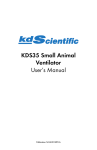
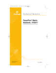
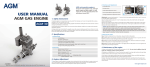
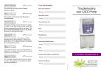
Model ‘680’
Small Animal Ventilator
User’s Manual
‘680’ Small Animal Ventilator
55-3438
Table of Contents
Harvard Apparatus Model ‘680’ Rodent Respirator Manual
1
SUBJECT
PAGE NO.
Table of Contents ..........................................................................................................1
General Information - Warranty and Repairs ................................................................2
Description....................................................................................................................3
Operations ....................................................................................................4-6
Changing Cylinders ......................................................................................................7
Volume Calibration ......................................................................................................8
General Information
Harvard Apparatus Model ‘680’ Rodent Respirator Manual
2
Serial Numbers
All inquires concerning our product should refer to the serial number of the unit. Serial numbers are located on the rear of the chassis.
Calibrations
All electrical apparatus is calibrated at rated voltage and frequency. While the flow will stay calibrated, the
peak will vary.
Warranty
Harvard Apparatus warranties this instrument for a period of one year from date of purchase. At its option,
Harvard Apparatus will repair or replace the unit if it is found to be defective as to workmanship or material.
This warranty does not extend to damage resulting from misuse, neglect or abuse, normal wear and tear, or
accident.
This warranty extends only to the original customer purchaser.
IN NO EVENT SHALL HARVARD APPARATUS BE LIABLE FOR INCIDENTAL OR CONSEQUENTIAL DAMAGES. Some states do not allow exclusion or limitation of incidental or consequential
damages so the above limitation or exclusion may not apply to you. THERE ARE NO IMPLIED WARRANTIES OF MERCHANTABILITY, OR FITNESS FOR A PARTICULAR USE, OR OF ANY
OTHER NATURE. Some states do not allow this limitation on an implied warranty, so the above limitation may not apply to you.
If a defect arises within the one-year warranty period, promptly contact Harvard Apparatus, Inc. 84
October Hill Road, Building 7, Holliston, Massachusetts 01746-1371 using our toll free number 1-800272-2775. Goods will not be accepted for return unless an RMA (returned materials authorization) number has been issued by our customer service department. The customer is responsible for shipping charges.
Please allow a reasonable period of time for completion of repairs, replacement and return. If the unit is
replaced, the replacement unit is covered only for the remainder of the original warranty period dating from
the purchase of the original device.
This warranty gives you specific rights, and you may also have other rights which vary from state to state.
Repair Facilities and Parts
Harvard Apparatus stocks replacement and repair parts. When ordering, please describe parts as completely as possible, preferably using our part numbers. If practical, enclose a sample or drawing. We offer a complete reconditioning service.
CAUTION
This pump is not registered with the FDA and is not for clinical use on human patients.
Description
Harvard Apparatus Model ‘680’ Rodent Respirator Manual
3
Series 680 Constant Volume Ventilators are positive pressure pumps designed for small rodents. They consist of a shunt wound motor operated by a solid state motor speed control, linkages, cylinder and piston
assembly and cam operated slide valve. All of the mechanics and electronics are contained in a sheet metal
housing and mechanism plate.
The linkages are so designed the piston almost touches the end of the cylinder at each stroke, regardless of
the stroke volume. This insures that virtually all of the air taken into the pup is expelled at each stroke. The
volume is adjustable while the pump is running by means of a crank knob on the top. Volume is indicated
by graduation marks on the transparent cylinder.
The pump is designed to use one of two different sized pistons and cylinder. In both cases the range of piston travel (5 c.m.) is the same. Model 680 is furnished with one 5 cc and one 10 cc cylinder and piston
assembly. Model 681 is furnished with one 10 cc and one 30 cc cylinder and piston assembly. The larger
cylinder is factory installed and the smaller supplied separately.
A three-way slide valve is attached to the mechanism plate at end of cylinder, and actuated by a cam on the
motor. The bottom port is the room air input, the middle port is the pump air output, while the two upper
ports are a pathway for the expired air.
Operation
Harvard Apparatus Model ‘680’ Rodent Respirator Manual
4
OPERATION
Series 680 pumps are equipped with a three wire grounded cord. The grounding should be kept intact.
Hook-Up to Animal
A “y” connection should be inserted between the connection to the animal (cannula, etc.), and the two
tubes coming from the pump. Dead space is minimized if the “y” is as close to the animal as possible.
See attached sketch.
Rate and Volume
The stroke volume is adjusted by the crank knob at the top of the pump with the volume being indicated on the cylinder graduations. The rate is adjusted on the top panel motor control, with knob.
Expired air can be collected at the exhaust top vertical tube.
Maintenance
The entire pump mechanism is available for inspection by removing the bottom panel. All bearings
and points of sliding contact should be lubricated every 30 days with machine oil of 20-30 grade. A
finger full of the silicone lubricant should be smeared inside the cylinder and on cam surface every 90
days or so.
The motor should be lubricated in accordance with the motor manufacturer’s direction.
Operation (Cont’d)
Harvard Apparatus Model ‘680’ Rodent Respirator Manual
5
Replacement Cylinders and Pistons
Each replacement syringe cylinder and piston consists of a set: cylinder and piston.
Catalog
Number
Description
683
Replacement 5cc cylinder and piston for Model 680 only.
684
Replacement 10cc cylinder and piston for Models 680 and 681
685
Replacement 10cc cylinder and piston for Model 681 only.
682
Repair Kit for 680-681
––––––––––––––––––––––––––––––––––––––––
(Diagram 1 - Model 680 Rodent Respirator Valve Hook-Up to Animal)
Output
(one-way valve)
‘Y’ Connection
(as close to
animal as possible)
Connection
Tube
Animal Expired Air
Pump Air
Cylinder
Room Air or
Non-explosive
Mixture
Valve
Block
Optical Recycling
Section Drawing
Harvard Apparatus Model ‘680’ Rodent Respirator Manual
6
––––––––––––––––––––––––––––––––––––––––
(Diagram 2 - Section Showing Cam at Hith Point)
Valve Block
0680-145
5013-017
0680-067
5013-017
5137-019
5009-037
Piston
5020-182
5009-035
5114-001
Cylinder
5013-027 (30cc)
5013-018 (10cc)
5013-019 (5cc)
5011-015
5008-014
Changing Cylinders
Harvard Apparatus Model ‘680’ Rodent Respirator Manual
7
INSTRUCTION
(CAUTION: UNPLUG UNIT) To change different size cylinders, remove crank knob in top of unit, the
(6) screws holding control cover in place. Move control cover aside without disconnecting wires. Loosen
two (2) 4-40 set screws on top of block on piston shaft. Slide piston and shaft back towards bearings and
then loosen two screws in valve block and remove cylinder an “o” rings. Remove piston by holding hex fitting next to piston and uncouple hex nut. Do not lose neoprene spacers in nut. Put back replacement piston in reverse manner as removing. Couple replacement cylinder and “o” ring on valve block, replace screws
and push piston and rod to end. Pull back about 1/32" for clearance. Be sure crank is on furthest inward
stroke. Finally lock down block set screws on shaft flat, replace cover and crank knob. Plug cord (110 VAC)
in and your pump is ready to operate.
CAUTION - Valve block should never be removed from mounting plate to change cylinders and pistons.
To do so may derange proper valve air cycling.
Volume Calibration
Harvard Apparatus Model ‘680’ Rodent Respirator Manual
8
PROCEDURE
If you have reason to suspect that the output volume of the pump at any given setting is not comparable to
the graduation marks on the pump cylinder, here is a simple, accurate method for testing calibration:
1.
Set the speed control dial to about 20 strokes per minute. Set the pump piston for a volume of 5
cc and stop the pump motor when the piston reaches its most rearward position, that is, when the
cylinder contains 5 cc of air.
2.
Attach a clean, freely moving 10 cc glass syringe to a short (2") length of tubing and “y” connector. Adjust the syringe plunger so that 1 or 2 cc of air is in the syringe.
3.
Attach the two arms of the “y” connector to the lower two ports of the valve block. Use short
lengths of tubing. This will establish a closed system between the pump cylinder and the syringe
so that the air will move back and forth from the pump to the syringe. Minimum dead-space
between the pump ports and the syringe will assure an accurate test.
4.
Turn on the pump and observe the excursion of the syringe plunger as it moves back and forth.
Hold the syringe horizontally to minimize the effect of gravity on the plunger travel. The limits
of its travel will indicate the actual amount of air being supplied by the pump at each stroke.
5.
To check stroke volume use a free moving 50 cc glass syringe and connect with a single short rubber tube to output one-way valve port. With pump piston in maximum stroke position run pump
(about 20 strokes/ min) and observe how many strokes it takes to get to 50 cc. i.e. - On 5 cc pump
stroke should take 10 strokes.
Should the foregoing tests show error in volume output of pump, the most probable cause is air leakage or
valve cycling adjustment. The air leakage can be in the “o” ring seals, valve cylinder and piston. If there is
any doubt, the “o” rings should be removed and new ones installed. Use Repair Kit, Cat. No. 682.
To readjust slide valve is a more difficult problem. The mechanism assembly must be removed from the
chassis. Follow instructions as in changing cylinders, i.e. remove control panel and volume adjustment
knob, cylinder and piston. Remove bottom cover. Also remove four holding screws, two on top of chassis
and two on side. DO NOT REMOVE VALVE ASSEMBLY. Mechanism now should come out through
the bottom of chassis. By clamping right hand side in a vise, motor can be run and all further volume checks
can be made.
Run motor and stop at the point where the high side of cam is pushing valve spindle and push rod to its
uppermost position. At this point on pressurizing 3 psi the room air inlet port, there should be no leakage
past the slide valve. If bad leakage occurs the slide valve should be adjusted upwards. To do this, loosen
check nut on pushrod and unscrew capscrew. It should be moved just enough to shut off air intake. When
this condition is obtained all other port cycling should be automatically sequenced. To check, run motor
to put cam lobe on lowest position. On output port, remove hex faced tube and remove spring and ball
valve. Replace hex faced tube and pressurize this port. There should be no leakage past slide valve at this
point.
If this slide valve assembly is ever removed from mechanism plate, it should be rechecked for adjustment.
The setting of the slide valve is quite critical to efficient pump operation. All volumes should be rechecked
as before.