1
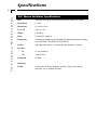
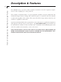
Model ‘687’
Mouse Ventilator
User’s Manual
Model ‘687’ Mouse Ventilator
55-7066
Table of Contents
H a r v a r d A p p a r a t u s Pico Plus S y r i n g e P u m p
1
SUBJECT
PAGE NO.
Table of Contents ..................................................................................1
General Information - Warranty and Repairs..........................................2
Specifications ..........................................................................................3
Description & Features ..........................................................................4
Initial Set-Up ..........................................................................................5
Pump Operation..................................................................................6-8
Connecting to Animal ....................................................................6
Selecting Rate & Volume ................................................................7
Setting Volume & Rate....................................................................8
Using Gas Mixtures ........................................................................8
Maintenance ..........................................................................................9
Changing Piston & Cylinder ..........................................................10-11
General Information
2
H a r v a r d A p p a r a t u s Pico Plus S y r i n g e P u m p
Serial Numbers
All inquires concerning our product should refer to the serial number of the unit. Serial numbers are located on the rear of the chassis.
Calibrations
All electrical apparatus is calibrated at rated voltage and frequency. While the flow will stay
calibrated, the peak will vary.
Warranty
Harvard Apparatus warranties this instrument for a period of one year from date of purchase. At its
option, Harvard Apparatus will repair or replace the unit if it is found to be defective as to workmanship or material.
This warranty does not extend to damage resulting from misuse, neglect or abuse, normal wear and
tear, or accident.
This warranty extends only to the original customer purchaser.
IN NO EVENT SHALL HARVARD APPARATUS BE LIABLE FOR INCIDENTAL OR
CONSEQUENTIAL DAMAGES. Some states do not allow exclusion or limitation of incidental or consequential damages so the above limitation or exclusion may not apply to you.
THERE ARE NO IMPLIED WARRANTIES OF MERCHANTABILITY, OR FITNESS
FOR A PARTICULAR USE, OR OF ANY OTHER NATURE. Some states do not allow
this limitation on an implied warranty, so the above limitation may not apply to you.
If a defect arises within the one-year warranty period, promptly contact Harvard Apparatus,
Inc. 84 October Hill Road, Building 7, Holliston, Massachusetts 01746-1371 using our
toll free number 1-800-272-2775. Goods will not be accepted for return unless an RMA
(returned materials authorization) number has been issued by our customer service department. The customer is responsible for shipping charges. Please allow a reasonable period of
time for completion of repairs, replacement and return. If the unit is replaced, the replacement
unit is covered only for the remainder of the original warranty period dating from the purchase of the original device.
This warranty gives you specific rights, and you may also have other rights which vary from
state to state.
Repair Facilities and Parts
Harvard Apparatus stocks replacement and repair parts. When ordering, please describe parts
as completely as possible, preferably using our part numbers. If practical, enclose a sample or
drawing. We offer a complete reconditioning service.
CAUTION
This pump is not registered with the FDA and is not for clinical use on human patients.
Specifications
H a r v a r d A p p a r a t u s Pico Plus S y r i n g e P u m p
3
‘687’ Mouse Ventilator Specifications
Rate
Adjustable from 18 to 150 strokes/min while the ventilator is running
Phase Ratio
1:1 fixed
Dimensions,
H x L xW
25 x 32.5 x 15 cm
(10 x 13 x 6 in)
Weight
8 kg (18 lb)
Power
115/230 VAC, 50/60 Hz
Stroke Rate
Continuously variable from 0-150 strokes/min while the ventilator is running,
with LIGHT-EMITTING DIODE (LED) DISPLAY.
Volume
Adjustable from 0.05 to 1 cc/stroke while the ventilator is running
Port Size:
ID
2.2 mm (0.086 in)
OD
4 mm (5/32 in)
Catalog No.
55-7066
Accessory
55-5281
Overhaul Kit for Mouse Ventilator; contains O-rings, valve springs,
lubricants, etc. to overhaul Ventilator
Description & Features
H a r v a r d A p p a r a t u s Pico Plus S y r i n g e P u m p
4
The MODEL 687 is a positive volume ventilator intended to meet the respiratory requirements of mice weighing up to 250 g (0.55 lb).
This ventilator is furnished with a 1 cc piston/cylinder assemblie of 0.05-1.0 ml/breath. The
mechanical design features a linkage that enables the piston to touch the end of the cylinder
at each stroke regardless of the volume. This assures that all the air/gas mixture taken into the
ventilator is expelled at each stroke.
A positive mechanical slide valve is actuated by a cam on the motor to synchronize inspiration
and expiration with the motion of the piston. Any NON-EXPLOSIVE gas/air mixture can
be used with the ventilator. A three-way slide valve is attached to the mechanism plate at the
end of the cylinder and actuated by a cam on the motor.
THIS VENTILATOR IS NOT TO BE USED IN AN EXPLOSIVE ATMOSPHERE OR
WITH ANY EXPLOSIVE GASES SUCH AS ETHER OR CYCLOPROPANE, ETC.
THESE VENTILATORS ARE NOT EXPLOSION-PROOF.
Initial Set-Up
H a r v a r d A p p a r a t u s Pico Plus S y r i n g e P u m p
5
1.
Read the Manual.
2.
Model 687 is supplied with a 115/220 voltage selector slide switch located near the
power cord, allowing the Pump to be operated at voltages between 100 and 130 VAC
or 220 to 240 VAC at 50/60 Hz. Pumps are shipped with the selector switch set at 115
V. For voltages other than 115V, it will be necessary to cut off the existing line cord
connector and install an appropriate one.
An international color coded line is supplied. Observe the proper polarity when installing a
new connector.
Brown
Blue
Green
3.
–
–
–
high
neutral
ground
Turn on main power switch located on the rear panel. The display will now illuminate.
The number displayed is the current strokes per minute rate.
Operating the Pump
6
H a r v a r d A p p a r a t u s Pico Plus S y r i n g e P u m p
Connection to the Animal
The vertical slide valve has four ports (see figure below):
◆ The top port is the return channel from the animal, which leaves the Pump at the
port on the side.
It is at this top port that expired air can be collected or recycled.
◆
The middle port is the room air/gas channel to the animal.
◆
The bottom port is the room air or gas mixture intake.
Note: It is important that the tubes to and from the animal be as short as possible.
The actual connection to the animal can be either:
◆
Tracheal cannula
◆
Endotracheal tube with or without a cuff
A selection of trachael cannula and endotracheal tubes are listed in the Harvard Bioscience
Catalog. It is important that the volume of tubing shared by inspired and expired air (dead
space) be kept to a minimum by having the “Y” or “T” connector as close to the animal as
possible.
“Y” Connector
(close to animal)
From Animal
ANIMAL
Expired Air
Tracheal
Cannula
or
Endotracheal
Tube
EXHAUST
To Animal
TO ANIMAL
OUT
Air/Gas Input
IN
ROOM AIR
Cylinder & Piston
Operating the Pump
7
100
70
200
300 400
600 800 1
3
2
4
5 6
8 10
15
20
30
500
Tidal Volume (ml Ambient Temperature)
H a r v a r d A p p a r a t u s Pico Plus S y r i n g e P u m p
Ventilator Graph
Tidal Volume vs. Weight & Rate
for Laboratory Mammals in Resting State.
(Apparatus dead space must be added)
40
500
400
400
300
300
200
200
150
150
100
100
80
80
60
50
60
50
Breaths per Minute: 10
40
40
40
30
30
15
50
20
20
20
15
15
25
60
10
8
10
8
70
80
90
30
6
6
5
5
4
4
100
3
3
2
2
40
1
1
0.8
0.8
0.6
0.5
0.6
0.5
0.4
0.4
70
100
200
300 400
600 800 1
(Grams)
2
Tidal Volume
3
4
5 6
8 10
15
20
30
40
(Kilograms)
Selection of Rate and Volume
Refer to the Respiration Chart (figure 2) to select the appropriate tidal
volume and respiration rate as a function of animal body weight. As a rough guide
an adult rat will weigh between 200 and 500 grams with tidal volumes between 0.6
to 1.25 cm3 with respiration rates between 66 to 210 breaths/min. The average rate
is 100 breaths/min. For most rodents the 5 cc cylinder will be adequate. For larger animals it will be necessary to change the cylinder.
Operating the Pump
H a r v a r d A p p a r a t u s Pico Plus S y r i n g e P u m p
8
Setting Volume
The volume delivered is read by observing the excursion of one of the O-rings on
the piston relative to the volume scale on the cylinder, e.g. piston ring oscillates
between 1 to 4 cc, volume delivered is 3 cc. Volume change is accomplished while
the Pump is running by turning “volume” knob in the desired direction.
Setting Rate
Adjust the “Rate” control until the desired rate appears on the LED display. Avoid
running the Pump at rates exceeding 150 breaths/min for periods in excess of 2
hours. Under certain conditions this will cause the motor to become quite hot and
the built-in thermal overload will shut down the motor until it cools down.
CAUTION - Do not over inflate the animal. A good rule of thumb is to observe the
depth of respiration in the normal calm unanesthetized animal and adjust the volume
to approximate this respiration depth when the animal is attached to the ventilator.
Use of Gas Mixture
It is possible to introduce non-explosive air/gas mixtures into the lower room air
port. However, the source of gas mixture is usually from a tank delivering gas is
at a constant rate while the Pump takes in air/gas intermittently. Some sort of
buffer/expansion chamber must be provided between the tank and the Pump. Any
kind of expandable bag, such as an anesthesia bag, rubber glove or Cryovac freezer bag can be used. Adjust the flow from the tank so that the bag neither over
inflates or collapses completely. This Pump is not designed to take air/gas inputs
under pressure.
An alternate method of introducing air/gas mixtures is to use a 9 to 12 ft length of
open tubing connected to the input port with a “T” connector located close to the
port. Air/gas is introduced into the “T”, filling the tube when the Pump is delivering air/gas to the animal and drawing in air/gas from the tube while the animal is
exhaling.
Maintenance
9
H a r v a r d A p p a r a t u s Pico Plus S y r i n g e P u m p
Maintenance
No special maintenance is required other than periodic lubrication of the piston Orings and the slide valve with the special non-toxic grease provided. To get to the
slide valve for lubrication:
1.
Remove the four screws holding the valve to the 1/4" aluminum black back plate.
2.
Remove the screws in front that hold the cylinder and valve together.
3.
Lift entire valve assembly up and out of Pump.
4.
Pull stainless steel valve rod and spring assembly free of valve block.
5.
Lubricate sparingly.
Model 687 Rodent Ventilator Replacement Parts
CYLINDER
1 cc 0687-012
VALVE BLOCK
ASSEMBLY
0687-010
PISTON
1 cc 0687-013
(2) O-RING
1 cc 5013-016
PISTON SHAFT
(2) SCREWS
#4-40 x 1-1/8
5101-165
O-RING
5013-051
HELICAL
COUPLING
5108-026
Lubrication
This Model 687 Respiration Pump is shipped with Pink Grease to lubricate piston
O-rings in cylinders and for metal to metal applications such as the inside of the
slide valve.
Maintenance
10
H a r v a r d A p p a r a t u s Pico Plus S y r i n g e P u m p
This Respirator Pump is furnished with a 1 cc piston and cylinder.
Note: It is extremely important when removing piston and cylinders that they be
aligned to be concentric and in line with the piston shaft.
The cylinder is fastened to the 4 port vertical slide valve by means of two screws located
between the “room air inlet” port and the “to animal” port on the front of the slide valve.
The vertical slide valve is fastened to the black 1/4" aluminum sub base by four screws located on the opposite side from the printed label. By using these six screws, two in front and four
on the side, alignment adjustments are made (see below).
Horizontal
Adjustment
Vertical
Adjustment
Maintenance
H a r v a r d A p p a r a t u s Pico Plus S y r i n g e P u m p
11
To remove the cylinder and piston
1. Set the pump volume to maximum.
2.
Run Pump at lowest speed and stop the Pump when the helical coupling is exposed.
3.
Using a 0.050 Allen wrench (provided), disconnect the white piston
from the coupling, leaving the coupling on the piston shaft.
4.
Remove the two screws located in the front of the slide valve.
5.
Remove piston and cylinder.
6.
Be careful to save the O-ring that is recessed in the slide valve block
between the screws. The O-ring provides the airtight seal between
the plastic cylinder and the valve block.
To install the piston and cylinder
1. Pick out the new piston and cylinder.
2.
Using pliers, remove the piston and lubricate with the pink grease
provided.
3.
Insert the lubricated piston in the cylinder so that the rear of the piston is flush with the rear of the cylinder with the 1/8" diameter coupling stud protruding.
4.
Fasten the cylinder to the valve block with the two screws, making
sure the O-ring is in place. Do not tighten these two screws completely, but just enough to hold the cylinder in place.
5.
The object of alignment is to have the stud at the end of the piston
be exactly in line with its mating hole in the helical coupling. This
insures that the piston moves freely within the cylinder without undue
friction.
6.
The two screws at the front of the valve block control left to right
alignment while the four screws at the rear of the slide valve control
up and down alignment. By adjustment of these 6 screws the proper alignment can be made. Remember that the screws interact with
one another so the procedure may have to be repeated one or more
times.
7.
When proper alignment is achieved, the helical coupling should be
connected. If alignment is correct, the coupling should slide onto the
piston stud without bending of the piston rod.
H a r v a r d A p p a r a t u s Pico Plus S y r i n g e P u m p
Notes:
12