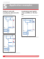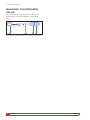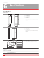
1
Ferrite kit
Accessory for timing of GIS circuit breakers using
TM1800 with DualGround™
User’s Manual
WWW.MEGGER.COM
ZP-CG04E
Ferrite kit
Accessory for timing of GIS circuit breakers using
TM1800 with DualGround™
User’s Manual
NOTICE OF COPYRIGHT & PROPRIETARY RIGHTS
© 2009, Megger Sweden AB. All rights reserved.
The contents of this manual are the property of Megger Sweden
AB. No part of this work may be reproduced or transmitted in
any form or by any means, except as permitted in written license
agreement with Megger Sweden AB. Megger Sweden AB has made
every reasonable attempt to ensure the completeness and accuracy
of this document. However, the information contained in this
manual is subject to change without notice, and does not represent
a commitment on the part of Megger Sweden AB. Any attached
hardware schematics and technical descriptions, or software
listings that disclose source code, are for informational purposes
only. Reproduction in whole or in part to create working hardware
or software for other than Megger Sweden AB products is strictly
prohibited, except as permitted by written license agreement with
Megger Sweden AB.
TRADEMARK NOTICES
Megger® and Programma® are trademarks registered in the U.S.
and other countries. All other brand and product names mentioned
in this document are trademarks or registered trademarks of their
respective companies.
Megger Sweden AB is certified according to ISO 9001 and 14001.
Megger Sweden AB
Eldarvägen 4
Box 2970
SE-187 29 TÄBY
Sweden
ZP-CG04E
T +46 8 510 195 00
F +46 8 510 195 95
[email protected]
www.megger.com
Ferrite kit
3

Contents
1 Safety
____________________________________ 6
5 Application examples
___________________________________ 16
1.1 General................................................................ 6
Without and with transformer disconnector............. 16
1.2 Safety instructions................................................ 6
Insulated ground switch only available on
the bus bar....................................................... 16
2 Introduction
____________________________________ 8
Application area......................................................... 8
Principle of a ferrite.................................................... 8
When is a ferrite required................................... 8
2 Kit description
___________________________________ 10
Insulating ground switches missing.......................... 17
Cable grounded in another substation..................... 17
Generator circuit breaker set-up............................... 18
6 Specifications
___________________________________ 20
Index....................................................................... 22
Ferrite kit parts......................................................... 10
3 Basics
___________________________________ 12
Prerequisites............................................................ 12
Insulated ground switch.................................... 12
Shape of shunts and spacing between shunts and
casing............................................................... 12
Shunts need to have insulation washers............ 12
Flexible cables with ferrites attached................. 12
Alternative paths for the ground current........... 13
Maneuver shafts............................................... 13
Shielded cables................................................. 13
All other ground connections............................ 13
Too many parallel ground connections.............. 13
Too long measurement loop............................. 13
4 Mounting / Set-up
___________________________________ 14
Mounting combinations........................................... 14
Attaching the hook and loop fastener ............. 14
How to connect the DCM-cables............................. 14
Set mode for DCM and tune the system.................. 15
How to enter the GIS mode.............................. 15
To switch back to normal mode........................ 15
Tuning.............................................................. 15
4
Ferrite kit
ZP-CG04E

ZP-CG04E
Ferrite kit
5
1 Safety
1
Safety
1.1 General
1.2 Safety instructions
Sharp edges
Important
Read and comply with the following instructions.
Always comply with local safety regulations.
6
Ferrite kit
The ferrites have sharp edges and have to be handled
by care to avoid personal injury.
Fragile
The ferrites are very fragile and need to be handled
with care. For example dropping the ferrite to the
ground will most probably cause that it will crack. Due
to this there is no warranty on damaged ferrites.
ZP-CG04E
1 Safety
ZP-CG04E
Ferrite kit
7
2 Introduction
2
Introduction
Application area
Principle of a ferrite
Time measurement, using TM1800 with Dynamic
Capacitive Measurement (DCM), on Gas Insulated
Switchgear (GIS) Circuit Breakers (CB) grounded on
both sides using ground switches / earth switches.
One property of the ferrite is that it increases the
impedance of a conductor it surrounds. Since the
DCM technology uses high frequency AC current as
test current we can take advantage of this property to
increase ground loop impedance.
When is a ferrite required
Ferrites are needed when the ground loop has low
impedance compared to the circuit breaker loop. On
Air Insulated Switchgear (AIS) ferrites are normally not
required due to that the ground loop is considerably
longer than the circuit breaker loop. On GIS breakers, though, the ground loop is usually about the
same length as the circuit breaker loop and therefore
ferrites are required to increase the impedance in the
ground loop.
8
Ferrite kit
ZP-CG04E
2 Introduction
Test leads
Test leads
Circuit breaker loop
Circuit breaker
loop
Ground loop
Ground loop
CB
CB
To DCM module
Insulation
Insulation
Ferrite
Ferrite
To
ToDCM
DCMmodule
module
Test leads
Circuit breaker loop
Ground loop
Test
leads module
To
DCM
To
DCM
module
Circuit breaker loop
Ground loop
To DCM module
To DCM module
Relation between ground loop and CB loop on GIS, open
air and dead tank circuit breaker.
ZP-CG04E
Ferrite kit
9
2 Kit description
2
Kit description
Ferrite kit parts
Designation
Pcs
Art.No.
Transport case
1
GD-00440
C-shape ferrite
7
XB-40010
I-shape ferrite
4
XB-40020
Round ferrite
4
30-67090
Hook and loop
fastener
4
09-10140
User’s Manual
1
ZP-CG04E
10
Ferrite kit
ZP-CG04E
2 Kit description
ZP-CG04E
Ferrite kit
11
3 Basics
3
Basics
Prerequisites
Flexible cables with ferrites
attached
Insulated ground switch
If the dimensions of the shunt and/or the spacing
don’t allow attaching a ferrite, the shunt can be
replaced by a flexible cable on which a round shaped
ferrite can be attached.
At least one of the ground switches need to be of
insulated type, i.e. there must be a part, connected to
the inner conducting part (through the closed ground
switch), that is possible to disconnect electrically by
detachable jumpers or shunts.
CB
Conducting part
Important
Before replacing the shunt with a cable
the following points must be obeyed:
Always comply with local safety regulations.
Insulation
Ferrite
Detachable shunt
Insulated ground switch with shunt and ferrite attached
Shape of shunts and spacing
between shunts and casing
The shunts have to be shaped in a way that it is possible to attach a ferrite around it. Likewise, there must
be enough space between the shunt and the casing
of the ground switch to fit a ferrite.
Shunts need to have insulation
washers
The circuit breaker must be closed and
grounded on both sides.
The shunt replacement (cable) must be
mounted before the shunt is removed.
The cable must have the same as, or better conducting capability than, the shunt.
The shunt replacement must be approved
by the manufacturer of the GIS circuit
breaker.
Examples of flexible cables with ferrites
attached
The bolts holding the shunts have to be equipped
with insulation washers. If not, attaching ferrites
around the shunts will have no effect since the current
is conducted through the bolts.
Insulation washer
Ferrite
Grounding shunt
Insulation washer
No insulation washer
Current path with and without insulation washer
12
Ferrite kit
ZP-CG04E
3 Basics
All other ground connections
In some installations the isolated part of the ground
switch is not only grounded through the shunts but
also has a separate grounding bar. In such case ferrites
need to be applied on the grounding bar.
Too many parallel ground
connections
A parallel shunt / ground connection decreases the
impedance by half although ferrites are applied on
both paths. If there are too many parallel shunts/connections to ground the resulting impedance might
be too low for DCM to sense a difference between
closed an open circuit breaker. Where the limit of
number of parallel paths is cannot be stated generally,
but has to be tested out from installation to installation.
On the contrary, putting ferrites in series on the same
shunt / ground connection increase the impedance.
So this might be a solution when there are too many
parallel paths to ground.
Too long measurement loop
Alternative paths for the ground
current
To achieve desired functionality ferrites must be applied on all shunts and/or devices that interconnect
the insulated part of the ground switch to ground, for
example:
Maneuver shafts
The DCM measurement circuit is optimized for best
amplitude response when connected to GIS circuit
breakers having reasonable distance between ground
switches, say 10 m (33’), however, distances up to 20
m (66’) might be managed.
Note This is not guaranteed functionality, and it has
to be tested out from case to case.
Long distances between groundings can be found in
out-door GIS installations or if the bus bar is equipped
with an insulated ground switch.
The ground switch might be operated by a maneuver shaft that transfers the power from the operating mechanism to the switch, in case the operating
mechanism is externally located. If this maneuver shaft
is made of a conducting material you need to apply a
ferrite around it. If the same maneuver shaft operates
all three phases, ferrites need to be applied between
the phases to separate them from each other.
Shielded cables
If there is a signal cable going to the ground switch it
is most likely of shielded type and then it is necessary
to apply a ferrite around the cable.
ZP-CG04E
Ferrite kit
13
4 Mounting / Set-up
4
Mounting / Set-up
Mounting combinations
Important
Always comply with local safety regulations.
There are three mounting possibilities with the ferrite
kit:
A] Round ferrite to attach on cables or maneuver shafts
B] C-shape combined with I-shape when the
spacing between shunt and casing is small
C] Two C-shapes when the shunt is thicker than
12 mm (½ ”)
Combination B and C
How to connect the DCMcables
The access point for one of the test lead clamps is
on the isolated part of the ground switch. However,
choosing the second access point might not be
equally obvious.
The principles for selecting measurement lead access
points are:
▪▪The longer ground loop the better
▪▪The shorter loop through the circuit breaker the
better
So, if there is a choice of access points the most
suitable ones according to the above rules should be
selected.
In most cases though it is sufficient to connect the test
clamps on each side of the ferrite.
Attaching the hook and loop
fastener
If the space between shunt and casing is small it
might be wise to first apply the hook and loop fastener
to the I-shaped ferrite before it is entered behind the
shunt, and then apply the C-shaped ferrite.
Note To obtain full effect of the ferrites they must
be fastened tight together, without any air
gap between the contact surfaces.
14
Ferrite kit
ZP-CG04E
4 Mounting / Set-up
Set mode for DCM and
tune the system
The TM1800 DCM module has two modes – Normal
mode and GIS mode. The difference between the
two modes is that the GIS mode is more sensitive.
After starting TM1800 the DCM mode is always reset
to normal mode.
2] Press the TUNE button shortly.
The tuning is performed automatically channel by channel and its corresponding LED
flashes. Tuning will take about half a minute
and when finished all channel LEDs, with
cables connected, will be lit.
3] Proceed as a normal time measurement.
▪▪The normal mode shall be used on open air circuit
breakers.
▪▪The GIS mode shall be used for GIS circuit breakers
but it can also be used for open air circuit breakers
having one interrupter per phase.
How to enter the GIS mode
1] Keep the TUNE button pressed down for
more than five seconds.
The DCM module will confirm the mode
change by flashing all LEDs simultaneously.
Once the TUNE button is released the tuning will start
in opposite channel order, i.e. beginning with channel
C2 and ending with channel A1.
The reversed tuning order is an indication of that the
DCM module is in GIS mode.
To switch back to normal mode
1] Keep the TUNE button pressed down for
more than five seconds.
The DCM will confirm the mode change by
flashing all LEDs simultaneously.
Once the TUNE button is released the tuning will start
beginning with channel A1 and ending with channel C2.
Note If tuning is not successful (LEDs off after
completed tuning) it could hint that the
impedance of the circuit is too low. To fix this
problem the DCM cables between the small
box and the clamps can be spread from each
other.
If you move the position of a DCM cable’s
high frequency part (between small box
and circuit breaker) you need to re-tune the
system. The same applies if ferrites are moved/
added/removed.
Tuning
Once all ferrites are attached the system need to be
tuned. This must be done when the circuit breaker is
in closed position.
1] Check that the circuit breaker is in closed
position.
ZP-CG04E
Ferrite kit
15
5 Application examples
5
Application examples
Without and with
transformer disconnector
Insulated ground switch
only available on the bus
bar
Both are possible with DCM.
In this example the B bus bar need to be taken out of
A
service.
B
A
B
A
A
B
B
CB
CB
CB
CB
GIS
GIS
GIS
GIS
A
B
Measurement lead access points are shown with red arrows.
CB
GIS
Measurement lead access points are shown with red arrows.
16
Ferrite kit
ZP-CG04E
5 Application examples
Insulating ground switches
missing
Cable grounded in another
substation
Access points outside GIS e.g. on transformer or line.
In these examples ferrites might be needed on the
transformer and line grounding.
Important
Before you connect the test leads you
must confirm that there is less than 0.7
A
volts potential difference between the
B
access points
when the circuit breaker is
open.
A
B
No ferrites needed in this example. Access point to
conducting part of cable can, on certain GIS designs,
CB
be found at the bushing where the cable connects to
the GIS. On some designs an insulation cone can be
removed to get access to the conducting part.
CB
A
B
GIS
GIS
CB
Optional ferrite
Line
Optional ferrite
A
A
B
B
GIS
Cable grounded in
another substation
CB
Measurement lead access points are shown with red arrows.
GIS
Optional ferrite
Line
Measurement lead access points are shown with red arrows.
ZP-CG04E
Ferrite kit
17
5 Application examples
Generator circuit breaker
set-up
No ferrites needed in this example. The generator’s
winding gives sufficient impedance in the ground
loop.
G
GCB
Measurement lead access points are shown with red arrows.
18
Ferrite kit
ZP-CG04E
5 Application examples
ZP-CG04E
Ferrite kit
19
6 Specifications
6
Specifications
Specifications
Dimensions
A
B
C
D
E
F
F
C-shape ferrite
Note: Measures does not include hook and loop
A
E
101.5 mm (4")
20.5 mm (0.81")
37.5 mm (1.48")
13.5 mm (0.53")
85.5 mm (3.37")
8 mm (0.31")
fastener
D
C
B
I-shape ferrite
A
B
C
102 mm (4.02")
7.5 mm (0.3")
37.5 mm (1.48")
Note: Measures does not include hook and loop
A
fastener
B
C
A
B
C
55.5 mm (2.18")
43 mm (1.69")
26 mm (1.02") Max. cable diam. 25.4 mm (1")
C
Round ferrite
A
Hook and
loop fastener
B
26 X 290 mm (1.02 X 11.4")
Transport case 390 x 310 100
(15.4" x 12.2" x 3.9")
Weight
20
4.5 kg (9.9 lbs)
total kit including transport case
Ferrite kit
ZP-CG04E
6 Specifications
ZP-CG04E
Ferrite kit
21
Index
Index
A
Application examples..................................... 16
C
Connect the DCM-cables............................... 14
C-shape ferrite................................................ 10
F
Flexible cables................................................ 12
G
GIS mode....................................................... 15
Ground current............................................... 13
Ground switch................................................ 12
H
Hook and loop fastener...........................10, 14
I
Insulated ground switch.................................. 12
Insulation washers.......................................... 12
I-shape ferrite................................................. 10
M
Maneuver shafts............................................. 13
Measurement loop.......................................... 13
Mounting......................................................... 14
N
Normal mode.................................................. 15
P
Parallel ground connections........................... 13
Principle of a ferrite.......................................... 8
R
Re-tune........................................................... 15
Round ferrite................................................... 10
S
Set mode for DCM.......................................... 15
Shielded cables.............................................. 13
Shunts............................................................ 12
T
Tune the system............................................. 15
22
Ferrite kit
ZP-CG04E
Your “One Stop” Source for all your electrical test equipment needs
▪▪
Battery Test Equipment
▪▪
Cable Fault Locating Equipment
▪▪
Circuit Breaker Test Equipment
▪▪
Data Communications Test Equipment
▪▪
Fiber Optic Test Equipment
▪▪
Ground Resistance Test Equipment
▪▪
Insulation Power Factor (C&DF) Test Equipment
▪▪
Insulation Resistance Test Equipment
▪▪
Line Testing Equipment
▪▪
Low Resistance Ohmmeters
▪▪
Motor & Phase Rotation Test Equipment
▪▪
Multimeters
▪▪
Oil Test Equipment
▪▪
Portable Appliance & Tool Testers
▪▪
Power Quality Instruments
▪▪
Recloser Test Equipment
Megger is a world leading manufacturer and supplier of test and measurement instruments used
within the electric power, building wiring and
telecommunication industries.
▪▪
Relay Test Equipment
▪▪
T1 Network Test Equipment
▪▪
Tachometers & Speed Measuring Instruments
With research, engineering and manufacturing
facilities in the USA, UK and Sweden, combined
with sales and technical support in most countries,
Megger is uniquely placed to meet the needs of its
customers worldwide.
▪▪
TDR Test Equipment
▪▪
Transformer Test Equipment
▪▪
Transmission Impairment Test Equipment
For more information about Megger and its diversified line of test and measurement instruments:
www.megger.com
▪▪
Watthour Meter Test Equipment
▪▪
STATES® Terminal Blocks & Test Switches
▪▪
Professional Hands-On Technical and
Megger is certified according to ISO 9001 and
14001.
▪▪
Safety Training Programs
Megger is a registered trademark
UK
Archcliffe Road, Dover
CT17 9EN England
T +44 (0) 1304 502101
F +44 (0) 1304 207342
E [email protected]
Other Technical Sales Offices
Dallas USA
Norristown USA
Toronto CANADA
Trappes FRANCE
Oberursel GERMANY
Johannesburg SOUTH AFRICA
Kingdom of BAHRAIN
Mumbai INDIA
Chonburi THAILAND
Sydney AUSTRALIA
WWW.MEGGER.COM
SWEDEN
Megger Sweden AB
Eldarvägen 4
Box 2970
SE-187 29 TÄBY
T +46 8 510 195 00
F +46 8 510 195 95
E [email protected]
Subject to change without notice. Printed matter No. ZP-CG04E Doc. CG1842BE 2009