1
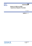
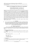
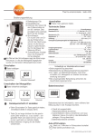
Strömungswächter
Flow Meter FC50
FS10-EX
Description
Compact single point flow monitor with 4 ... 20 mA analogue output
and MIN or MAX monitoring options. 10 x LED bar which shows the
actual flow speed and the status of the switching point. Suitable for
water, oil and air. Available as screw-in type, plug-in type for sensor
adapter TP/ball valve BV or push-in type.
1
Features
• wear-resistant compact design, with stainless steel 1.4571 monitoring head and housing
• 4 … 20 mA analogue output (4 mA = 0 m/s, 20 mA = operating
range final value)
• switch point can be adjusted steplessly or to 10 predefined values
regardless of the actual flow speed
• 10 x LED bar (red, green, orange) which shows the actual flow
speed and the status of the switching point
• fluid temperature -25 ... 100 °C (screw-in type, plug-in type for
sensor adapter TP/ball valve BV) and -25 ... 130 °C (push-in type)
respectively
• M12 plug-in electrical connection
• signal output with HighSide-FET output
• protected against short circuits and overloads
FC50
Electrical connection
+UB
1
2
FC50
4
-UB
3
braun/brown
2
weiß/white
Analogausgang/analogue output
+ DC 24 V
3
blau/blue
–
weiß/white
schwarz/black
blau/blue
Meldeausgang
signal output
Last/load
max. 500 mA
Analogausgang
analogue output
Last/load
max. 500 Ω
– Minus
minus
1
braun/brown
+
4
schwarz/black
Meldeausgang/signal output
Stiftkontakte DIN EN 50044 bzw. IEC 947
M12x1 4-polig
plug-in connector DIN EN 50044 or IEC 947
M12x1 4 pole
Ordering information
Flow meter (calorimetric)
FC50 in compact housing
Power supply
U1 DC 24 V
Flow switching point
MIN minimum switching point
MAX maximum switching point
Analogue output
C11 4 … 20 mA (0 m/s … operating range final value)
Operating range
FB2 operating range final value 100 m/s (air), 4 m/s (water, oil)
FB1 operating range final value 25 m/s (only air)
Fluid
A air
W water
S special fluid, e.g. oil
Process connection
00 push-in type - without flange, threaded installation bush as accessory
01 screw-in type, G1/2A (to DIN 3852-A), length 36 mm
02 screw-in type, NPT1/2“-14, length 36 mm
11 plug-in type (following DIN ISO 6149), length 18.2 mm for TP or BV adapters
Fitting material
M1 stainless steel 1.4571
Electrical connection
E12 M12x1, 4-pole
Certification
T0 without certificate *)
FC50 - U1 MIN C11 FB2
A
01 M1 E12 T0 ordering information
* for detailed information please see section 0.
www.flowvision-gmbh.de
2011
177
Flow Meter FC50
TECHNICAL DATA (TU = 25 °C, UB = DC 24 V)
General data
FC50
Suitable for
1
air, water, oil
Temperature range
fluid
-25 ... +100 °C (-13 … +212 °F) / -25 ... +130 °C (-13 … +266 °F) (5)
ambience
-25 ... +65 °C (-13 … +149 °F)
Status indication
10 x LED bar (red, green, orange)
Electrical data
Operating voltage UB
DC 24 V (18 ... 32 V)
Power consumption (without load)
ca. 75 mA
Analogue output
flow speed
4 … 20 mA (12 bit), 4 mA = 0 m/s, 20 mA = operating range final value
Switching output
flow speed
Power FET, high side switch, short circuit proof
max. load 500 mA, inductive load max. 100 mA
Connection to DIN 50044
Flow measurement
Measuring range
(operating range)
Accuracy (4)
(in measuring range)
Reproducibility
M12 plug-in connection, 4-pole
(6)
air, operating range FB1
0 ... 20 m/s (0 ... 25 m/s) – FB1, see ordering information
air, operating range FB2
0 ... 20 m/s (0 ... 100 m/s) – FB2, see ordering information
water, oil
0 ... 3 m/s (0 ... 4 m/s) – only FB2, see ordering information
air
± 2 % of measured value ± 2 % of measuring range final value
water 0 … 2 m/s
± 1 % of measured value ± 3 % of measuring range final value
water 2 … 3 m/s
± 8 % of measuring range final value
± 1 % of measured value ± 0,5 % of measuring range final value
(1)
air (3)
Response time
water
oil
Temperature drift
approx. 8 s
(2)
(2)
approx. 2 s
approx. 5 s
air (+10 … +70 °C)
± 0,5 % of measured value/°C
water (+10 … +70 °C)
± 1 % of measured value/°C
plug-in type
following DIN ISO 6149
screw-in type
G 1/2 A, NPT 1/2”
push-in type
shank diameter 18 mm/0.709 in. without thread
plug-in type
100 bar
screw-in type
100 bar
push-in type
100 bar (observe pressure resistance of installation)
Mechanical data
Type and size
of monitoring head
Pressure resistance
of monitoring head
Degree of protection
Material
Weight
(3)
(4)
(5)
(6)
(1)
(2)
178 2011
IP67 (when plugged in)
fitting (wetted)
stainless steel 1.4571
sensor (wetted)
stainless steel 1.4571
connection sensor/fitting
laser welded
housing
stainless steel 1.4571
M12 connector
CuZn, nickel-plated
cap
PA
O-ring
Viton (FPM)
plug-in type
approx. 300 g
screw-in type
approx. 240 g
push-in type
approx. 740 g
at constant temperature and flow conditions, and stable thermal conductivity
delay with the switch point set to 1 m/s / 3.28 fps and the flow at 2 m/s / 6.56 fps, after a sudden complete stop
delay with the switch point set to 10 m/s / 32.8 fps and the flow at 20 m/s / 65.6 fps, after a sudden complete stop
the accuracy values were determined under ideal conditions:
- symmetrical complete flow profile
- correct mounting in the pipe
- inlets and outlets according to EN ISO 5167-1
the extended temperature range up to 130 °C/266 °F is only allowed with FC50...00... (push-in type) and a minimum distance of 15 cm (5.91 in) between electronic housing and fluid, in
this case max. ambient temperature must not exceed 50 °C (122 °F)
sensor calibration is performed at approx. 25 °C and approx. 970 mbar abs. (punctual measurement)
www.flowvision-gmbh.de
Flow Meter FC50
Operating range FB2 air
volume flow rate in
l/min
l/h
m3/h
1,67·106
108
105
1,67·105
107
104
16700
106
1000
1670
105
100
167
104
10
16,7
1000
1
1,67
100
0,1
0,167
10
0,01
0,017
1
0,001
0,01
DN500
DN350
DN300
DN250
DN200
DN150
DN125
DN100
DN80
DN65
DN50
DN40
DN32
DN25
DN20
DN15
0,03
0,1
0,3
1
3
10
30
1
100
average flow speed in m/s
Operating range water/oil
volume flow rate in
l/min
l/h
m3/h
1,67·106
108
105
1,67·105
107
104
16700
106
1000
1670
105
100
167
104
10
16,7
1000
1
1,67
100
0,1
0,167
10
0,01
0,017
1
0,001
0,01
DN500
DN350
DN300
DN250
DN200
DN150
DN125
DN100
DN80
DN65
DN50
DN40
DN32
DN25
DN20
DN15
0,03
0,1
0,3
1
3
10
30
100
average flow speed in m/s
www.flowvision-gmbh.de
2011
179
Flow Meter FC50
Dimensions
Einsteckanschluss
Plug-in type process connection
ø38
ø38
40
1
Gewindeanschluss
Screw-in type process connection
18.2
90.2
36
20
14
14
ø18
Arretierungsnut
locking slot
14
10
36
58
SW27
90
90
SW27
ø18
ø17.5
NPT1/2"-14
G1/2A
O-Ring 15,3x2,2 FPM (Viton)
in Anlehnung an DIN ISO 6149
O-ring 15.3x2.2 FPM (Viton)
following DIN ISO 6149
SW30
DIN 3852 Form A
DIN 3852 form A
Überwurfmutter G3/4"
cap nut G3/4"
53
BH
GM
Strömungsrichtung
ø38
Flow direction
Einschiebeanschluss
Push-in type process connection
Flow Switch
ON
-
+
Adj.
Q
M12x1
L = 300
SW15
14
ø18
All dimensions in mm
Die zur Verfügung gestellten Informationen sind nach unserem Wissen genau und zuverlässig,
jedoch übernimmt FlowVision keine Verantwortung für den Einsatz in einer Anwendung, die nicht
der vorliegenden Spezifikation entspricht. FlowVision behält sich das Recht vor, Spezifikationen
im Sinne des technischen Fortschritts jederzeit zu ändern. Maßänderungen sind vorbehalten, bei Bedarf bitte neuestes Maßblatt mit Toleranzen anfordern. Maße, Daten, Abbildungen
und Beschreibung entsprechen dem neuesten Stand bei Herausgabe dieses Kataloges,
sind aber unverbindlich! Änderungen sowie auch Irrtümer und Druckfehler vorbehalten. Die
Bestellbezeichnung der Geräte kann von deren Beschriftung abweichen.
180 2011
www.flowvision-gmbh.de
FC50…11… | Sensor adapter TP/Ball valve BV
Sensor adapter TP/Ball valve BV
Description
Sensor adapters TP and BV facilitate correct positioning and exchange
of FC50...11... (plug-in type connection) in pipes with process connection DN 15...DN 50.
Ball valve BV enables pressure-free installation or removal of FC50...11...
(plug-in type connection) simply by closing the input and output pipe.
The measuring points are suited to temporary measurements; after
completion of the measuring cycle they can be closed by means of
blanking plugs.
TP-...
1
BV-...
Ordering information
Features
Type
BV
ball valve with internal thread
Process connection/Nominal size
03 DN 25 G1
internal thread length: 88 mm/3.46 in.
04 DN 32 G1 1/4 internal thread length: 100 mm/3.94 in.
05 DN 40 G1 1/2 internal thread length: 110 mm/4.33 in.
06 DN 50 G2
internal thread length: 131 mm/5.16 in.
Material of the area exposed to fluid
M3
nickel plated brass, Delrin seal
BV -
03
M3 ordering example
•Correct positioning of sensor
•Ease of sensor replacement
•Measuring point can be closed if not used
•Sensor adapter available as screw-in or welding type
•Ball valve also serves as a shutoff valve (both input and out output)
Ordering information
Accessories
Description
Ref. No.
Blanking plug, brass, with O ring
0Z121Z000186
Union nut, brass
Y 306 901 01
Blanking plug, stainless steel 1.4571/AISI 316 Ti,
with viton O ring
0Z121Z000187
Union nut, stainless steel
Y 306 901 03
Welding set 05
0Z122Z000202
cap nut
4 mm
.158 in.
ø18 mm
ø.709 in.
Type
TP
Sensor adapter with internal thread
Process connection/Nominal size
01 DN 15 G 1/2 internal thread length: 50 mm/1.97 in.
02 DN 20 G 3/4 internal thread length: 64 mm/2.52 in.
03 DN 25 G1
internal thread length: 78 mm/3.07 in.
04 DN 32 G1 1/4 internal thread length: 94 mm/3.70 in.
05 DN 40 G1 1/2 internal thread length: 110 mm/4.33 in.
06 DN 50 G2
internal thread length: 138 mm/5.43 in.
Material of the area exposed to fluid
M1 stainless steel 1.4571/AISI 316Ti PN 315 bar/4570 psi
M3 brass (not TP-03..)
PN 25 bar/363 psi
M5 red brass (only TP-03..)
PN 16 bar/232 psi
TP -
01
M3 ordering example
ø23,8 mm
ø.937 in.
Ordering information
.717 in.
18,2 mm
retention pin
welded fitting
stainless steel 1.4571
Type
TP
Sensor adapter with welding nipples
Process connection/Nominal size
01 DN 15 dia.d: 16 mm/.630 in.
length: 80 mm/3.15 in.
02 DN 20 dia.d: 20 mm/.787 in.
length: 70 mm/2.76 in.
03 DN 25 dia.d: 25 mm/.984 in.
length: 80 mm/3.15 in.
04 DN 32 dia.d: 32 mm/1.26 in.
length: 100 mm/3.94 in.
05 DN 40 dia.d: 40 mm/1.57 in.
length: 110 mm/4.33 in.
06 DN 50 dia.d: 50 mm/1.97 in.
length: 140 mm/5.51 in.
Material of the area exposed to fluid
M1
stainless steel 1.4571/AISI 316Ti
Process connection
SA welded connection
TP -
www.flowvision-gmbh.de
01
M1 -
SA ordering example
2011
181
FC50...11… | Sensor adapter TP/Ball valve BV
Dimensions
TP-… sensor adapter with internal thread
ød
G
SW
1
t
t
SW = width across flats
L
Material stainless steel (-M1): PN 315 bar / 4569 psi
Material brass (-M3): PN 25 bar / 363 psi
Material red brass (-M5): PN 16 bar / 232 psi
Type
TP-01 …
TP-02 …
TP-03 …
TP-04 …
TP-05 …
TP-06 …
DN
mm
15
20
25
32
40
50
dia. d
G
in. mm in.
in.
.591 16 .630 1/2“
.787 20 .787 3/4“
.984 25 .984 1“
1.26 32 1.26 1.1/4“
1.57 40 1.57 1.1/2“
1.97 50 1.97 2“
t
mm
11
12
14
15
15
19
L
SW
in. mm in. mm in.
.433 50 1.97 27 1.06
.472 64 2.52 32 1.26
.551 78 3.07 40 1.57
.591 94 3.70 50 1.97
.591 110 4.33 55 2.16
.748 138 5.43 70 2.76
ød
øD
SW
TP-… M1-SA sensor adapter with welding nipples
t
t
L
PN 315 bar / 4569 psi
DN
Type
mm
15
20
25
32
40
50
TP-01M1-SA
TP-02M1-SA
TP-03M1-SA
TP-04M1-SA
TP-05M1-SA
TP-06M1-SA
dia. d
dia. D
t
L
SW
in. mm in. mm in. mm in. mm in. mm in.
.591 16 .630 21.3 .839 15 .591 80 3.15 27 1.06
.787 20 .787 26.9 1.06 15 .591 70 2.76 32 1.26
.984 25 .984 33.7 1.33 15 .591 80 3.15 40 1.57
1.26 32 1.26 42.4 1.67 15 .591 100 3.94 50 1.97
1.57 40 1.57 48.3 1.90 15 .591 110 4.33 55 2.16
1.97 50 1.97 60.3 2.37 15 .591 140 5.51 70 2.76
BV-… M3 Ball valve with internal thread
G
SW
ød
H
A
t
L
PN 25 bar / 363 psi
Type
BV-03M3
BV-04M3
BV-05M3
BV-06M3
DN
mm
25
32
40
50
dia. d
G
in. mm in.
in. mm
.984 25 .984 1“
21
1.26 32 1.26 1.1/4“ 24
1.57 40 1.57 1.1/2“ 24
1.97 50 1.97 2“
28
t
L
in.
.827
.945
.945
1.10
mm
88
100
110
131
SW
in. mm in.
3.47 41 1.61
3.94 50 1.97
4.33 54 2.13
5.16 70 2.76
H
mm
59
65
77
85
in.
2.32
2.56
3.03
3.35
A
mm
115
115
150
150
in.
4.53
4.53
5.91
5.91
mm
This is a metric design and millimeter dimensions take precedence ( inch )
182 2011
www.flowvision-gmbh.de
FC50…00… | Accessories
Accessories
Threaded installation bush
0Z122Z000196
Teflon sealing ring
0Z122Z000197
1
front sealing ring
union nut
Ø18
Ø.708
rear sealing
ring
Ø18
Ø.708
R 3/4´´
threaded installation bush
19
.748
52
2.05
SW 29
1.14 in.
SW 27
1.06 in.
Suitable up to 25 bar/2.5 MPa/363 psi if used with FC50…00….
(Observe instructions for installation.)
Caution:
Stainless steel ring is designed to cut into monitoring head.
Pressure resistant to 25 bar/2.5 MPa/363 psi.
Teflon ring can only be used from 0 to 2 bar/0,2 MPa/29 psi.
Please observe user manual and safety guidelines!
Locking set 01
0Z122Z000204
1
2
3
1 chain 4 x 32 DIN 5685 (approx. 1 m/3.28 ft)
2 catch for chain NG 5
3 clip with screw and nuts DN15 to DIN 11850
www.flowvision-gmbh.de
2011
183
FC50 | Cable type
Cable type 25 with connectors
Description
M12 plug-in electrical connection for connection of supply voltage
and switching output.
1
Technical data
Cable type 25
Features:
Ordering information
IP67 (only when connector plugged in)
Resistant to chemicals and oils
Temperature range:
-25 °C ... +80 °C
Contact resistance:
≤ 5 mΩ
Current carrying capacity:
4A
Insulation resistance:
> 10 Ω
Withstand voltage:
2,0 kVeff /60 s
184 2011
Typ
Do + Ka Typ 25 - 5 m
with connector to IEC60947-5-2, 4-pole,
M12 and PUR insulated cable 3x0.34 mm2
(AWG 22), halogen-free
Do + Ka Typ 25 - 5 m
ordering example
9
www.flowvision-gmbh.de