1
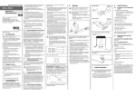
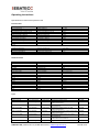
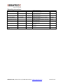
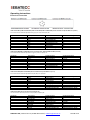
Operating instructions Magnetic Door Process Lock UMZ X.X-‐xxx-‐Mxx, (-‐Rxx) Dear Customer, For correct operation and for your own safety, please carefully read the attached instructions for use prior to starting the installation. In case of any questions, please contact SEBATECC UG. Phone. ++49 (0) 9135 736 1463 email: [email protected] Instructions for use Any manufacturer’s personal liability is excluded in case of non-adherence to these instructions as well as in case of incorrect use of this device. Additionally warranty on device and accessories will expire. Devices Magnetic coil with connector according to EN 50044 applicable as electric bolt keeper in connection with ferromagnetic anchor plates. Technical data of magnetic coils in chart 1. Technical data of adapted sensors in manufacturer’s supplement. Function The product controls non security-relevant applications in process and automation technology. Conduct a functional test of all components. Installation For installation, maintenance and repair the relevant instructions must be observed. The electrical installation must be made by an electrical specialist under consideration of country-specific regulations. Prior to the installation, the indicated device code must be compared with the designated operating conditions to ensure operation in accordance with the regulations. Assembly The process bolt keeper can be assembled at swing doors with left or right swing or at sliding doors. Assemble the bolt keeper parallel opposite to the anchor plate. Fix the actuator non-detachably with safety screws or rivets. Application Magnetic bolts are electro-technical components. Operation without the respective anchor plate is not possible. The electric process bolt keeper can be supplemented by a corresponding sensor. Suitable sensors are listed as attachment. The process bolt keeper does not have a safety function. Remark: The installation instructions from the manufacturer of the sensors used must be observed. Maintenance The magnetic coils are maintenance-free. In the event of error or breakdown for unknown reason during operation, the magnetic bolts must be exchanged. Defective or broken magnetic coils or connectors must not be repaired. They must be exchanged. In case the magnetic coils are exposed to special strains, additional protective measures possibly must be taken. Project planning For safety-relevant functions, make a safety review of the entire system including all adapted safety-relevant components. SEBATECC UG, Gerbersleite 3A, 91085 Weisendorf, sebatecc@t-‐online.de Seite 1 von 7 Operating instructions Safety regulations Danger Risk of injury by improper application For safety-related functions to make sure a safety assessment of the entire system Danger Risk of injury by improper installation The product must be installed by qualified personnel, commissioned and serviced. Danger Risk of injury by improper use User manual and product data sheet read carefully. Necessarily provide instructions and information in this manual, the product data sheet sequence. Operation The electrical magnetic Bolt is dimensioned for 100% duty cycle (the permanent Magnetzuhaltung for 10% duty cycle) even in the worst ambient conditions allowed. In operation, make sure that neither the max. permissible ambient and fluid temperatures of 50 ° C nor the power limit (10 max.% overvoltage) are exceeded. If desired, the solenoid is to be protected against overload. To avoid voltage peaks that can lead to damage in the system, the user must provide appropriate protection measures. The surface of the magnet coil can get hot during continuous operation. Caution Personal injury from hot surfaces For continuous operation, do not touch the surface of the magnet coil. SEBATECC UG, Gerbersleite 3A, 91085 Weisendorf, sebatecc@t-‐online.de Seite 2 von 7 Operating instructions Caution Influence Please note that magnetic disk wiping, electronic and mechanical components, e.g. Effect on pacemakers, may or destroy. Negative effects of magnetic fields on the People who originate from permanent magnets, are not known to us. Able from direct contact to magnetic materials and systems allergic reactions occur (eg against ceramic and metallic Materials as well as zinc, nickel and plastics. For the operation of the sensors used by the user is to use the vendor's instructions. In particular, the correct assembly and checking the switching states is mandatory. Danger Injury due to improper application Always observe the manufacturer guide of the sensor. Sure to check the correct functioning of the sensor. SEBATECC UG, Gerbersleite 3A, 91085 Weisendorf, sebatecc@t-‐online.de Seite 3 von 7 Operating instructions Specifications of solenoid and process lock Electrical data Versorgungsspannung Ub Spannungstoleranz Leistungsaufnahme el. Mag. bei Ub Leistungsaufnahme pe. Magn. bei Ub Magnethaltekraft El.Magnet Magnethaltekraft Pe.Magnet Fixierkraft Einschaltdauer El. Magnet Einschaltdauer Pe. Magnet Chart1 Supply voltage Ub Voltage tolerance Power consumption el. at Ub Power consumtation pe. at Ub Magnetic holding force Magnetic holding force Fixing force Inrushtime el. Magnet Inrushtime pe. Magnet 24 VDC +/-‐ 10% 3,2 W/6 W 36 W 140 N/500 N 400 N 30 N 100% 10% Umgebungstemperatur EMV Temperatur Metallfläche Gewicht Chart 2 Ambiente temperature EMC Metal surface temperature Weight -‐20 -‐ +50°C EN 55011 75°C 500g Max. vertical offset Max. lateral offset Connecting type Cable Protection type Switch housing Anchor baseplate Anchor plate Dimensions UMZ Basic Sensor Height Width Depth Actuator Height Width Depth +/-‐ 2,5 mm +/-‐ 2,5 mm M12 8x0,25 mm² IP67 Alu, hart eloxiert Alu, hart eloxiert Stahl, vernickelt/Steel 110 mm 40 mm 33,5 mm 110 mm 45 mm 18 mm Mechanical data Höhenversatz Seitenversatz Anschlussart Leitung Schutzart Schaltergehäuse Anker Bodenplatte Ankerplatte Abmessungen UMZ Basic Sensor Höhe Breite Tiefe Betätiger Höhe Breite Tiefe Chart 3 Type Typ/Type Stück/Quantity Wirkweise Merkmale Bestell-‐Nr. UMZ 0.1-‐E145-‐ZZ UMZ 1.0-‐E475-‐MP 1 Inkl. Ankerplatte 1 Inkl. Betätiger El.-‐Magnetisch El.-‐Magnetisch 0514500 1047512 UMZ 1.0-‐P400-‐MP 1 Inkl. Betätiger Permanent UMZ 2.0-‐E475-‐MR 1 Inkl. Betätiger El.-‐Magnetisch UMZ 2.0-‐P400-‐MR 1 Inkl. Betätiger Permanent UMZ 3.0-‐E475-‐RMP 1 Inkl. Betätiger El.-‐Magnetisch UMZ 3.0-‐P400-‐RMP 1 Inkl. Betätiger Permanent UMZ 3.0-‐E475-‐RRP 1 Inkl. Betätiger El.-‐Magnetisch Magnetisches Zuhaltesystem Magnetisches Zuhaltesystem, mit M12 Sensoraufnahme Magnetisch/permanentes Zuhaltesystem, M12 Sensoraufnahme Magnetisches Zuhaltesystem, mit M18 RFID Sensoraufnahme Magnetisch/permanentes Zuhaltesystem, M18 RFID Sensoraufnahme Magnetisches Zuhaltesystem, mit rechteck Sensoraufnahme Magnetisch/permanentes Zuhaltesystem, mit rechteck RFID Sensoraufnahme Magnetisches Zuhaltesystem, mit rechteck 1040012 2047518 2040018 3047501 3040001 3047502 SEBATECC UG, Gerbersleite 3A, 91085 Weisendorf, sebatecc@t-‐online.de Seite 4 von 7 Operating instructions UMZ 3.0-‐P400-‐RRP 1 Inkl. Betätiger Permanent UMZ 4.0-‐E475-‐RRS 1 Inkl. Betätiger El-‐Magnetisch UMZ 13.0-‐E1000-‐RRP 1 Inkl. Betätiger El.-‐Magnetisch UMZ 14.0-‐E1000-‐RRS 1 Inkl. Betätiger El.-‐Magnetisch UMZ Betätigerplatte -‐M12 1 UMZ Betätigerplatte -‐M18 1 UMZ Betätigerplatte-‐R 1 UMZ Betätigerplatte-‐S 1 UMZ Montagewinkel Chart 4 1 RFID Sensoraufnahme Magnetisch/permanentes Zuhaltesystem, mit rechteck Sensoraufnahme Magnetisches Zuhaltesystem, mit rechteck RFID Sensoraufnahme Magnetisches Zuhaltesystem, mit rechteck RFID Sensoraufnahme Magnetisches Zuhaltesystem, mit rechteck RFID Sensoraufnahme Betätiger-‐/Ankerplatte beweglich, passend für UMZ 1.0/2.0xx-‐M12 Betätiger-‐/Ankerplatte beweglich, passend für UMZ 1.0/2.0xx-‐M18 Betätiger-‐/Ankerplatte beweglich, passend für UMZ 3.0xx-‐ Betätiger-‐/Ankerplatte beweglich, passend für UMZ 4.0xx-‐ Montagewinkel für Schwenktüren 3040002 4047502 13010002 14010002 1000012 2000018 3000020 4000020 4000001 SEBATECC UG, Gerbersleite 3A, 91085 Weisendorf, sebatecc@t-‐online.de Seite 5 von 7 Operating instructions Electrical connection UMZ 1.0-‐E475-‐M12/ UMZ 1.0-‐P400-‐M12/ UMZ 3.0-‐E475-‐RMP/ UMZ 3.0-‐P400-‐RMP (Sensor manufactured by Pilz PSEN ma1.3/ma1.4) The control of the solenoid operation PIN 5 (grey) 0V und/or PIN 8 (red) 24V PIN/Broche Farbe/Colour Funktion/Function 1 Weiß Sicherheitskontakt 2 2 Braun Meldeausgang + 3 Grün Sicherheitskontakt 1 4 Gelb Sicherheitskontakt 2 5 Grau Magnetansteuerung 0V 6 Rosa Sicherheitskontakt 1 7 Blau Meldeausgang -‐ 8 Rot Magnetansteuerung 24V UMZ 2.0-‐E475-‐MR/UMZ 2.0-‐P400-‐MR (Sensor manufactured by Rockwell 440N-‐21Z-‐M18, Sick TR 4) The control of the solenoid operation Pin 3 (green) 24V, Pin 7 (blue) -‐0V PIN/Broche Farbe/Colour Funktion/Function 1 Weiß Meldeausgang 2 Braun Sensorversorgung 3 Grün Magnetansteuerung 4 Gelb Eingang 2 5 Grau Sicherheitsausgang 1 6 Rosa Sicherheitsausgang 2 7 Blau Magnetansteuerung 0V 8 Rot Eingang 1 UMZ 3.0-‐E475-‐RRP/UMZ 3.0-‐P400-‐RRP (Sensor manufactured by Pilz PSEN cs 3.1/cs 4.1) The control of the solenoid operation Pin 8 (red) 24V, Pin 7 (blue) 0V Anschlussbezeichnung 0V 0V +24 VDC Anschlussbezeichnung Hilfsschalter A +24V UB +24VDC B+ A B 0V A+ PIN/Broche 1 2 3 4 5 6 7 8 Farbe/Colour Weiß Braun Grün Gelb Grau Rosa Blau Rot Funktion/Function Eingang Kanal 2 +24V UB Ausgang Kanal 1 Ausgang Kanal 2 Meldeausgang Eingang Kanal 1 0V Magnetansteuerung, 0V UB +24 V Magnetansteuerung Anschlussbezeichnung S21 A1 12 22 Y32 S11 0V UB Magnetansteuerung +24VDC Funktion/Function +24VDC UB Eingang Kanal 1 0V + 0V Magnet Sicherheitsausgang 1 Meldeausgang Eingang Kanal 2 Sicherheitsausgang 2 +24 V Magnetansteuerung Anschlussbezeichnung A1 X1 A2 Y1 OSSD 1 Info Out X2 Y2 OSSD 2 Magnetansteuerung +24VDC UMZ 4.0-‐E475-‐RRS (Sensor manufactured by SSP Safix S1) The control oft he solenoid operation Pin 8 (red) 24V, Pin 3(blue) 0V PIN/Broche 1 2 3 4 5 6 7 8 Farbe/Colour Weiß/white Braun/brown Grün/green Gelb/yellow Grau/grey Rosa/pink Blau/blue Rot/red SEBATECC UG, Gerbersleite 3A, 91085 Weisendorf, sebatecc@t-‐online.de Seite 6 von 7 Operating instructions CE-‐Marking The CE marking is not a quality characteristic, but an undertaking by the manufacturer to the user that the product complies with the requirements of the applicable directives.Enable the free movement of goods within the EU, the European Council adopted common guidelines for the European market, set the minimum requirements for health and safety. CE-‐ Identification is confirmed that products comply with the guidelines, ie compliant with relevant, especially harmonized standards. Note on Low Voltage Directive 2006/95/EG and MRL 2006/42/EG Electromagnetic actuators and sensors without the electronics company's connect are Components or components for installation into equipment or electrical equipment are provided, or only in conjunction with other components is a direct function exercise. They do not fall under the scope of the Low Voltage Directive. To ensuring the safety the products according to applicable DIN VDE 0580 manufactured and tested. The products are not covered by the Machinery Directive, as they called modules be responsible for building into machines, partly completed machinery or safety components are provided. A security and risk assessment is only in the intended use or reasonably foreseeable use possible and done by the user. Electromagnetic actuators and sensors without electronics are not covered by the above named Guidelines and may therefore not bear the CE mark. CE Marking according to the Electromagnetic Compatibility Directive 2004/108/EG List of named Sensors: • flexUMZ 3.0 Ø Pilz: PSEN cs 3.1p/cs 4.1p/ma 1.4p • flexUMZ 2.0 Ø Rockwell: 440N-‐21Z-‐S16H M18, Coded Ø Sick: TR 4 SAM 01C • flexUMZ 1.0 Ø Pilz: PSEN ma 1.3p • flexUMZ 4.0 Ø SSP: Safix SEBATECC UG, Gerbersleite 3A, 91085 Weisendorf, sebatecc@t-‐online.de Seite 7 von 7


![R・RSシリーズ寸法図一覧[PDF:1.5MB]](http://vs1.manualzilla.com/store/data/006550114_2-fa1e8f2785032e99c856f7238a45d452-150x150.png)