1
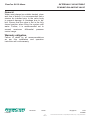
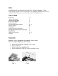
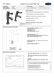
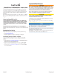
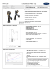
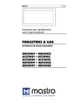
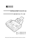
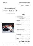
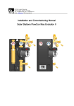
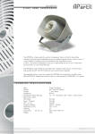
FlowCon SH 15-40mm
EXTERNALLY ADJUSTABLE
DYNAMIC BALANCING VALVE
INSTALLATION AND OPERATION INSTRUCTION
FlowCon SH 15-40mm, 1/2”-1 1/2”
Install the FlowCon SH valve either in
the supply or return pipe work for the unit.
It is recommended that a strainer be installed
prior to the valve body to prevent damage
or blockage due to debris. INSTALL THE
VALVE HOUSING WITH THE FLOW
DIRECTIONAL ARROW POINTING IN
THE CORRECT DIRECTION.
The valve body is available with double union
end connections, i.e. figure 1.
Two types of end connections are available
for use with the union nut:
Threaded (male or female):
The thread standard is ISO 228, which is a
straight metric thread (compatible with BS2779) or NPT threading standard, depending
on the end connections ordered. The threads
on both the connection and piping should
be cleaned carefully. As these models are
union end connected, the union nuts and
the end connections should be removed for
installation.
For all threaded connections please clear
threads on both valve and piping of debris.
Sealant such as pipe dope or teflon tape is
recommended. WHEN USING HEMP AS
PIPE SEALANT, ENSURE NO STRANDS
ARE LEFT IN THE VALVE OR PIPING.
Soldered end (sweat):
REMOVE THE END CONNECTIONS FROM
THE HOUSING BEFORE SOLDERING. THIS
ENSURES THAT THE O-RINGS AND
INTERNAL PARTS ARE NOT DAMAGED
BY HEAT.
Valve bodies are as standard supplied
with body tappings plugged.
Alternatively, the valve body can be ordered
with pressure/temperature fittings (p/t plugs)
for the body tappings. Before finger mounting the p/t plugs in the body tappings,
please seal the threads of the p/t plugs.
(DO NOT OVER TIGHTEN).
Figure 1
O-rings are supplied with the valve
body and used to seal the connections.
It is recommended to grease the o-rings
with a silicone grease before installation.
IMPORTANT: Never use mineral oil or petrol
based grease or oil on the o-rings. Please
make sure these are in place in the
o-ring grooves in the inlet and outlet of the
valve body, when installing the housing and
REMEMBER TO TIGHTEN THE UNION
NUTS TO ENSURE SEALING.
Denmark
Dubai
1A95000
-1-
DN
15/20/25
Singapore
USA
10/2008
FlowCon International assumes no responsibility for mistakes, if any, in any printed material.
FlowCon SH 15-40mm
EXTERNALLY ADJUSTABLE
DYNAMIC BALANCING VALVE
General.
Water must always be suitable treated, clean
and free of debris. It is recommended that a
strainer be installed prior to the valve body
to prevent damage or blockage due to debris. Ensure that the valve is not in the fully
closed position when filling the system with
water. Further, it is recommended not to
exceed maximum differential pressure
control range.
Warranty obligation.
Failure to abide by all recommendations
as per this installation and operation
instruction will void warranty.
Denmark
Dubai
1A95000
-2-
Singapore
USA
10/2008
FlowCon International assumes no responsibility for mistakes, if any, in any printed material.
FlowCon SH 15-40mm
EXTERNALLY ADJUSTABLE
DYNAMIC BALANCING VALVE
Flow rate setting, SH1 and SH2:
Flow rate
Valve size: DN15-DN25 · 1/2”-1”
Valve size: DN25-DN40 · 1”-1 1/2”
33-300 kPaD · 4.8-44 psid
33-300 kPaD · 4.8-44 psid
SH.1.1
l/sec
0.075
0.090
0.105
0.120
0.135
0.15
0.17
0.18
0.20
0.21
0.23
0.25
0.26
0.28
0.29
0.31
0.32
0.34
0.35
0.37
0.38
0.39
0.41
0.42
0.44
0.45
0.46
0.47
0.49
0.50
0.51
0.52
0.53
0.54
0.55
0.56
0.57
0.58
0.60
0.61
0.62
0.63
0.64
0.64
0.65
0.66
0.67
0.68
0.68
0.69
0.70
l/hr
270
324
378
432
486
540
598
655
713
770
828
886
943
1001
1058
1116
1166
1217
1267
1318
1368
1418
1469
1519
1570
1620
1663
1706
1750
1793
1836
1872
1908
1944
1980
2016
2059
2102
2146
2189
2232
2261
2290
2318
2347
2376
2405
2434
2462
2491
2520
Setting
SH.2.1
GPM
l/sec
l/hr
GPM
1.2
1.4
1.7
1.9
2.1
2.4
2.6
2.9
3.1
3.4
3.6
3.9
4.2
4.4
4.7
4.9
5.1
5.4
5.6
5.8
6.0
6.2
6.5
6.7
6.9
7.1
7.3
7.5
7.7
7.9
8.1
8.2
8.4
8.6
8.7
8.9
9.1
9.3
9.4
9.6
9.8
10.0
10.1
10.2
10.3
10.5
10.6
10.7
10.8
11.0
11.1
0.11
0.15
0.18
0.22
0.25
0.29
0.34
0.39
0.44
0.49
0.54
0.59
0.64
0.69
0.74
0.79
0.84
0.89
0.94
0.99
1.04
1.07
1.10
1.13
1.16
1.19
1.22
1.25
1.28
1.31
1.34
1.37
1.40
1.43
1.46
1.49
1.51
1.53
1.56
1.58
1.60
1.62
1.65
1.67
1.70
1.72
1.74
1.76
1.79
1.81
1.83
1.85
1.88
1.90
1.93
1.95
396
526
655
785
914
1044
1224
1404
1584
1764
1944
2124
2304
2484
2664
2844
3024
3204
3384
3564
3744
3852
3960
4068
4176
4284
4392
4500
4608
4716
4824
4932
5040
5148
5256
5364
5443
5522
5602
5681
5760
5846
5933
6019
6106
6192
6271
6350
6430
6509
6588
6674
6761
6847
6934
7020
1.7
2.3
2.9
3.5
4.0
4.6
5.4
6.2
7.0
7.8
8.6
9.4
10.1
10.9
11.7
12.5
13.3
14.1
14.9
15.7
16.5
17.0
17.4
17.9
18.4
18.9
19.3
19.8
20.3
20.8
21.2
21.7
22.2
22.7
23.1
23.6
24.0
24.3
24.7
25.0
25.4
25.7
26.1
26.5
26.9
27.3
27.6
28.0
28.3
28.7
29.0
29.4
29.8
30.1
30.5
30.9
Denmark
0.5
0.6
0.7
0.8
0.9
1.0
1.1
1.2
1.3
1.4
1.5
1.6
1.7
1.8
1.9
2.0
2.1
2.2
2.3
2.4
2.5
2.6
2.7
2.8
2.9
3.0
3.1
3.2
3.3
3.4
3.5
3.6
3.7
3.8
3.9
4.0
4.1
4.2
4.3
4.4
4.5
4.6
4.7
4.8
4.9
5.0
5.1
5.2
5.3
5.4
5.5
5.6
5.7
5.8
5.9
6.0
Dubai
1A95000
-3-
Use the special designed key
(FlowCon part no. ACC0001)
for micrometer setting.
A micrometer setting at 2.4 as
illustrated above corresponds
to a flow rate of:
0.29 l/sec
(for valve size DN15/20/25)
0.99 l/sec
(for valve size DN25/32/40).
Accuracy: Greatest of either
±5% of controlled flow rate or
±2% of maximum flow rate.
Singapore
USA
10/2008
FlowCon International assumes no responsibility for mistakes, if any, in any printed material.
FlowCon SH 15-40mm
EXTERNALLY ADJUSTABLE
DYNAMIC BALANCING VALVE
Assembly drawing FlowCon SH:
A1:
B:
C: D1:
D2:
E1:
Valve housing
Micrometer setting
Adjustment key
P/t plug (2 pcs.)
Plug and gasket (2 of each)
Union end connections.
C
Figure 2
E
E
B
A1
DN15/20
D1
D1
D2
Denmark
D2
Dubai
1A95000
-4-
Singapore
USA
10/2008
FlowCon International assumes no responsibility for mistakes, if any, in any printed material.