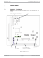
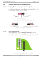
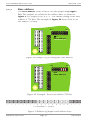
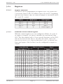
1
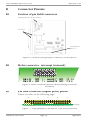
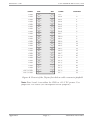
Meilhaus Electronic User Manual
ME-24 PC/104 1.0E
Embedded PC/104 TTL Digital I/O Board with three 8 bit
Ports
Impressum
User Manual ME-24 PC/104
Revision 1.0E
Date: 2008-06-17
Meilhaus Electronic GmbH
Fischerstrasse 2
82178 Puchheim/Germany
www.meilhaus.com
© Copyright 2008 Meilhaus Electronic GmbH
All rights reserved. No part of this publication may be reproduced
or distributed in any form whether photocopied, printed, put
on microfilm or be stored in any electronic media without the
expressed written consent of Meilhaus Electronic GmbH..
Important note:
The information contained in this manual has been reviewed with
great care and is believed to be complete and accurate. Meilhaus
Electronic assumes no responsibility for its use, any infringements
of patents or other rights of third parties which may result from
use of this manual or the product. Meilhaus Electronic assumes no
responsibility for any problems or damage which may result from
errors or omissions. Specifications and instructions are subject to
change without notice.
All trademarks acknowledged.
Revision 1.0E
User manual ME-24 PC/104
Contents
1 Introduction
1.1
1.2
1.3
1.4
5
Scope of Delivery
Features
System Requirements
Available Software
2 Installation
3 Hardware
7
9
3.1 Jumper Positions
3.2 Jumper Functions and Registers
3.2.1
3.2.2
3.2.3
3.2.4
5
5
6
6
Setting the connector pin 2 and 4 signal
External interrupt
Base address
Registers
9
10
10
10
12
13
Appendix
15
A
B
15
16
Specifications
Connector Pinouts
B1
B2
B3
C
Technical Questions
C1
C2
C3
Contents
Position of pin field/connectors
Molex connector - interrupt (external)
Pin field connector (digital ports) pinout
Fax hotline
Customer service address
Updates
Page 3
16
16
16
18
18
18
18
Meilhaus Electronic
Revision 1.0E
1
User manual ME-24 PC/104
Introduction
Dear customer,
Thank you for purchasing the ME-24 PC board! On purchase of
this board you have selected a high-quality technological product
that left our premises in perfect condition.
Please check that your delivery is complete and in good condition.
If any faults are obvious, please contact us immediately.
We recommend that you carefully read this manual before
installing the board - especially the installation chapter. This
also explains how the jumpers can be set for the various board
functions.
1.1
Scope of Delivery
It goes without saying that we make every effort to ensure that the
product package is complete. But to check whether your delivery
is complete, please check your package using the following list.
Your package should contain the following parts:
• TTL digital I/O board, ME-24 PC/104 type, for the ISA-based
embedded PC/104 form factor.
• Manual in PDF file format on the ME-Power-CD (optional
printed version).
• Molex mating connector for interrupt (external).
1.2
Features
The ME-24 has 24 TTL digital I/O channels. The ME-24 is an
ISA-based PC/104 board. The channels are grouped in three 8 bit
wide TTL ports. Each port can be configured as input or output
via software. With its extended temperature range and an
additional, external interrupt input, the ME-24 is the ideal solution
for industrial embedded systems.
Introduction
Page 5
Meilhaus Electronic
User manual ME-24 PC/104
Revision 1.0E
• Three 8 bit TTL digital I/O ports.
• Wide range of base addresses (base addresse selected via
jumper).
• Additional, external interrupt in put.
• Extended temperature range -40...+85°C.
• For the ISA-based PC/104 form factor.
1.3
System Requirements
The ME-24 will be used with a PC/104 stack with Intel® processor
or compatible.
1.4
Available Software
The ME-24 can directly be programmed on register level with
common programming languages/environments and operating
systems.
Meilhaus Electronic
Page 6
Introduction
Revision 1.0E
2
User manual ME-24 PC/104
Installation
When installing the board in a PC/104 stack do not use
inappropriate force. It should be possible to insert the board into
other PC/104 modules without a great deal of effort. Please note
the relevant regulations of the PC/104 standard for assembly.
Caution!
Risk of destroying highly sensitive components through
electrostatic discharge! Therefore, make sure you dissipate your
body‘s charge before installing the board, for example, by touching
a blank casing element on your computer.
Installation
Page 7
Meilhaus Electronic
Revision 1.0E
User manual ME-24 PC/104
3
Hardware
3.1
Jumper Positions
Figure 1 shows the jumper positions. They are referred to as ST1
to ST4.
Molex connector for external interrupt
ST4
A03
A04
A05
A06
A07
A08
A09
A10
A11
123
15
14
12
11
10
9
7
6
5
4
3
ST2
(IRQ)
1 2 3
ST2
(base address)}
50-pin flat ribbon cable
connector for I/O channels
ST1 (function of
pin2 and 4)
Figure 1: Jumper positions:
Hardware
Page 9
Meilhaus Electronic
User manual ME-24 PC/104
Revision 1.0E
3.2
Jumper Functions and Registers
3.2.1
Setting the connector pin 2 and 4 signal
With jumper ST1 you can set the signal available at the pins 2 and
4 of the 50-pin flat ribbon cable connector. The signal at pin 2 and
4 can either be GND or +12 V PC power.
1
2
3
ST1
GND
+12 V
Connector pin 2 and 4
Figure 2a: Jumper ST1 for pin 2 and 4 signal
1
2
3
1
2
3
ST1
ST1
Pin 2 and 4 to GND
Pin 2 and 4 output +12 V PC power
Figure 2b: Settings for jumper ST1
3.2.2
External interrupt
Jumper ST2 is used to set the interrupt (external). You can
select IRQ 3 - 7, 9 - 12, 14, 15 (see figure 2a). The default setting
for IRQ external is 7. The example below (see figure 2b) shows
how to set IRQ 9.
15
3
ST2
IRQ external
Figure 3a: Jumper ST2 sets the interrupt line
Meilhaus Electronic
Page 10
Hardware
Revision 1.0E
User manual ME-24 PC/104
15
3
ST2
IRQ external
Figure 3b: Example - IRQ 9 for external interrupt
Hardware
Page 11
Meilhaus Electronic
User manual ME-24 PC/104
3.2.3
Revision 1.0E
Base address
The base address of the board is set with jumper ST3 (figure
3a). The jumpers are related to the address lines as shown in
figure 4. If a jumper is set, it is “1”. The default setting of the base
address is 750 Hex. The example in figure 3b shows how to set
the address 700 Hex:
A3
A11
ST3
Base address
Figure 4a: Jumper ST3 for setting the base address
A3
A11
ST3
Base address
Figure 4b: Example - how to set address 700 Hex
A19 A18 A17 A16 A15 A14 A13 A12 A11 A10 A9
0
0
0
0
0
0
0
0
0
1
1
A8
A7
A6
A5
A4
A3
A2
A1
A0
1
0
0
0
0
0
0
0
0
=> 11100000000 => 700 Hex
Figure 5: Relation of jumpers and address lines
Meilhaus Electronic
Page 12
Hardware
Revision 1.0E
User manual ME-24 PC/104
3.2.4
Registers
3.2.4.1
Register functions
The ME-24 can be programmed on register level. Die board uses
4 successive bytes in the I/O address space of your PC, beginning
with the base address (BA) set with the jumper as described above
(R = read, W = write):
Offset
BA + 4
BA + 5
BA + 6
BA + 7
3.2.4.2
8 bit register
Port A
Port B
Port C
Control register
Functions of the control register
With the control register you can configurate all lines of a port to
be inputs or outputs. The ME-24 emulates the well known chip
8255. The bits marked with “x” have special functions on the 8255,
but are not used on the ME-24. The have the status “don’t care”
and can be set to 0 or 1 with no difference. Port C is divided, the
lower and upper 4 bits (or lines) can be configured as inputs or
outputs:
x
x
x
x
x
x
x
x
x
x
x
x
x
x
x
x
Hardware
Read/write
R/W
R/W
R/W
W
Controll word
(base address + 7)
x x 0 0 x 0
x x 0 0 x 0
x x 0 1 x 0
x x 0 1 x 0
x x 0 0 x 1
x x 0 0 x 1
x x 0 1 x 1
x x 0 1 x 1
x x 1 0 x 0
x x 1 0 x 0
x x 1 1 x 0
x x 1 1 x 0
x x 1 0 x 1
x x 1 0 x 1
x x 1 1 x 1
x x 1 1 x 1
0
1
0
1
0
1
0
1
0
1
0
1
0
1
0
1
Port A
Port B
Output
Output
Output
Output
Output
Output
Output
Output
Input
Input
Input
Input
Input
Input
Input
Input
Output
Output
Output
Output
Input
Input
Input
Input
Output
Output
Output
Output
Input
Input
Input
Input
Page 13
Port C
Upper
Lower
Output
Output
Output
Input
Input
Output
Input
Input
Output
Output
Output
Input
Input
Output
Input
Input
Output
Output
Output
Input
Input
Output
Input
Input
Output
Output
Output
Input
Input
Output
Input
Input
Meilhaus Electronic
Revision 1.0E
User manual ME-24 PC/104
Appendix
A
Specifications
PC/104 interface
Bus interface
Base addresse
Interrupt
Digital I/O
Lines, ports
Level
External interrupt
General Data
Power consumption
Size
24 I/O lines grouped in three 8 bit wide,
bidirectional ports. Each port programmable
as input or output
Output level: UOL max. 0.5 V at 24 mA
UOH min. 2.4 V at -24 mA
Input level:
UIL max. 0.8 V at VCC = 5 V
UIH min. 2 V at VCC = 5 V
Input current: ±1 µA
Directly sent to system, if enabled.
Level: TTL, see digital I/O channels
Temperature range
Humidity
40 mA (no load)
(mm) 90 x 96 (board only), 105 x 96 x 24
(board incl. connectors)
PC/104 bus connector and 1x flat ribbon
cable connector, 10-pin Molex for interrupt
(external, Molex mating connector included)
-40…+85°C
20…55% (non condensing)
CE certification
EC directive
Emission
Immunity
89/336/EMC
EN 55022
EN 50082-2
Connectors
Appendix
ISA-16 bit-based PC/104 embedded bus
Jumper selectable in a wide range, the
jumpers correspond to the address lines
A3…A11
External interrupt input, jumper selectable
3…7, 9…12, 14, 15
Page 15
Meilhaus Electronic
User manual ME-24 PC/104
Revision 1.0E
B
Connector Pinouts
B1
Position of pin field/connectors
Interrupt (external) - Molex connector
PC/104 bus
Pin field for the
ports A - C
Figure 6: Position of the pin field connectors on the ME-24
B2
Molex connector - interrupt (external)
1 2 3 4 5 6 7 8 9 10
1
2
IRQ In 1 3
IRQ In 2 4
GND
GND
5
6
reserved
reserved
7
8
GND
GND
9 n. c.
10 n. c.
Figure 6: Molex connector pinout (Molex mating connector
included)
B3
Pin field connector (digital ports) pinout
Pinout see table on the following page!
49 47 45 43 41 39 37 35 33 31 29 27 25 23 21 19 17 15 13 11 9 7 5 3 1
Leiterplatte
50 48 46 44 42 40 38 36 34 32 30 28 26 24 22 20 18 16 14 12 10 8 6 4 2
Figure 7: 50-pin pinfield of the ME-24, view from front side
Meilhaus Electronic
Page 16
Appendix
Revision 1.0E
User manual ME-24 PC/104
Name
GND
GND
GND
GND
GND
GND
GND
GND
GND
GND
GND
GND
GND
GND
GND
GND
GND
GND
GND
GND
GND
GND
GND
+12 V/GND
+12 V/GND
Pin
50
48
46
44
42
40
38
36
34
32
30
28
26
24
22
20
18
16
14
12
10
8
6
4
2
Pin
49
47
45
43
41
39
37
35
33
31
29
27
25
23
21
19
17
15
13
11
9
7
5
3
1
Name
+5V
PA 0
PA 1
PA 2
PA 3
PA 4
PA 5
PA 6
PA 7
PB 0
PB 1
PB 2
PB 3
PB 4
PB 5
PB 6
PB 7
PC 0
PC 1
PC 2
PC 3
PC 4
PC 5
PC 6
PC 7
Channel
0
1
2
3
4
5
6
7
8
9
10
11
12
13
14
15
16
17
18
19
20
21
22
23
Figure 8: Pinout of the 50-pin flat ribbon cable connector/pinfield
Note: Pins 2 and 4 can either be GND or +12 V PC power. Use
jumper ST1 to select (see description of the jumpers).
Appendix
Page 17
Meilhaus Electronic
User manual ME-24 PC/104
Revision 1.0E
C
Technical Questions
C1
Fax hotline
If you have technical questions or problems relating to the board, please
send a detailed description of the problem to our hotline:
Fax hotline:
within Germany:
from abroad:
(089) 89 01 66-28
++49 - 89 - 89 01 66-28
Email hotline:
[email protected]
C2
Customer service address
We hope that you will never need this part of the manual. If your
board has a technical defect, please contact us at:
Meilhaus Electronic GmbH
Abteilung Reparaturen
Fischerstrasse 2
D-82178 Puchheim, Germany
If you want to return your board for repair, please enclose
a detailed description of the error including details of your
computer/system and the software used! The simplest method is to
use our RMA procedure which you will find online at
www.meilhaus.com/en/service/rma-procedure/
C3
Updates
The current drivers for Meilhaus Electronic boards and our
manuals in PDF format are available from www.meilhaus.de
Meilhaus Electronic
Page 18
Appendix
Revision 1.0E
User manual ME-24 PC/104
Index
Symbols
8255 13
A
10
Jumper Positions 9
L
Appendix 15
B
Level 15
M
Base address 12
C
Molex connector 16
P
Connectors 15
Connector Pinouts 16
Controll word 13
control register 13
Customer service address 18
PC/104 interface 15
Port A 13
Port B 13
Port C 13
Position of pin field/connectors
16
D
Digital I/O 15
R
Registers 13
Register functions 13
RMA procedure 18
E
Email hotline 18
External interrupt 10
S
F
Scope of Delivery 5
Setting the connector pin 2 and 4
signals 10
Size 15
Specifications 15
System Requirements 6
Fax-Hotline 18
Features 5
Functions of the control register
13
H
Hardware 9
T
Technical Questions 18
Temperature range 15
I
Installation 7
interrupt 10
IRQ 10
U
Updates 18
J
jumper 9, 10, 12
Jumper Functions and Registers
Appendix
Page 19
Meilhaus Electronic