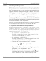
1
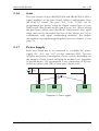
Meilhaus Electronic Manual
ME-MultiSig
1.5E
(ME-MUX32, ME-DEMUX32, ME-SIG32)
Analog Multiplexing/Demultiplexing System
with optional Signal Conditioning Modules
up to 8192 Channels
Imprint
Manual ME-MUX32, ME-DEMUX32, ME-SIG32
Revision 1.5E
Revised: 22. June 2005
Meilhaus Electronic GmbH
Fischerstraße 2
D-82178 Puchheim/Munich
Germany
http://www.meilhaus.com
© Copyright 2005 Meilhaus Electronic GmbH
All rights reserved. No part of this publication may be reproduced or distributed
in any form whether photocopied, printed, put on microfilm or be stored in any
electronic media without the expressed written consent of Meilhaus Electronic
GmbH.
Important note:
The information contained in this manual has been reviewed with great care and
is believed to be complete and accurate. Meilhaus Electronic assumes no responsibility for its use, any infringements of patents or other rights of third parties
which may result from use of this manual or the product. Meilhaus Electronic assumes no responsibility for any problems or damage which may result from errors
or omissions. Specifications and instructions are subject to change without notice.
Borland Delphi is a trademark of Borland International Inc.
Turbo/Borland C is a trademark of Borland International Inc.
Visual C++ and Visual Basic are trademarks of the Microsoft Corporation.
VEE Pro and VEE OneLab are trademarks of Agilent Technologies.
ME-VEC and ME-FoXX are trademarks of Meilhaus Electronic.
Other company names and product names found in the text of this manual are
also trademarks of the companies involved.
Manual ME-MultiSig
Rev. 1.5E
Table of Contents
1
Introduction ....................................................................................... 5
1.1 Package Contents ....................................................................... 5
1.2 Features....................................................................................... 6
1.3
1.4
2
Supported PC Boards ............................................................... 8
Model Overview ....................................................................... 9
Hardware ........................................................................................... 10
2.1 General Notes .......................................................................... 10
2.2 Pullup/Pulldown Resistors ...................................................... 10
2.3
2.4
2.5
Model ”Multiplexer” ................................................................ 12
2.3.1 Multiplexer Master Board (ME-MUX32-M) ........................ 12
2.3.2 Multiplexer Slave Board (ME-MUX32-S) ............................ 13
2.3.3 Standard System Expansion ................................................. 14
2.3.4 Full System Expansion .......................................................... 15
2.3.5 Jumper Settings ..................................................................... 17
2.3.6 Gain ..................................................................................... 19
2.3.7 Power Supply ....................................................................... 19
2.3.8 Operating Mode ”Single-MUX”............................................. 20
2.3.8.1 Block Diagram ”Single-MUX” (Master Board)...... 21
2.3.8.2 Block Diagram ”Single-MUX” (Slave Board) ........ 22
2.3.9 Operating Mode ”Multi-MUX” .............................................. 23
2.3.9.1 Block Diagram ”Multi-MUX” (Master Board) ....... 24
2.3.9.2 Block Diagram ”Multi-MUX” (Slave Board).......... 25
Model ”Demultiplexer” ............................................................ 26
2.4.1 Demultiplexer Base Board (ME-DEMUX32) ...................... 26
2.4.2 Operating Mode ”Demux” .................................................... 27
2.4.3 Block Diagram ”Demux” ...................................................... 28
Model ”Signal Conditioning”................................................... 29
2.5.1 Signal Conditioning Base Board (ME-SIG32) ...................... 29
2.5.2 Operating Mode ”Signal Conditioning”................................ 30
2.5.3 Block Diagram ”Signal Conditioning”................................. 31
Meilhaus Electronic
Page 3
Table of Contents
Rev. 1.5E
2.6
3
Manual ME-MultiSig
Plug-On Modules ..................................................................... 32
2.6.1 Calculating the measured values.......................................... 32
2.6.2 Module ME-Proto ................................................................. 34
2.6.3 Module ME-Diff16 ................................................................ 35
2.6.4 Module ME-Current16 ....................................................... 36
2.6.5 Module ME-RTD8
............................................................ 37
2.6.5.1 2-Wire Connectivity .............................................. 38
2.6.5.2 3-Wire Connectivity .............................................. 38
2.6.5.3 4-Wire Connectivity .............................................. 39
2.6.5.4 Calculating the Temperature ................................ 40
2.6.6 Modul ME-TE8 ................................................................... 42
2.6.6.1 Basics of Thermocouples ..................................... 43
2.6.6.2 Linearity ................................................................. 44
2.6.6.3 Limiting Deviation ................................................ 45
2.6.6.4 Calculating the Temperature ................................ 46
Programming..................................................................................... 49
3.1 Control Signals Overview ..................................................... 50
3.2 Gain Setting ............................................................................. 51
3.3
3.4
Base Board Identification ..................................................... 52
General Reset .......................................................................... 53
3.5
Multiplexing ........................................................................... 54
3.5.1 Operating Mode ”Single-Mux” .................................... 54
3.5.2 Operating Mode ”Multi-Mux” ...................................... 56
Demultiplexing ........................................................................ 58
Signal Conditioning ................................................................ 59
3.6
3.7
Appendix.................................................................................................. 61
A
B
C
D
E
Specifications............................................................................ 61
Pinouts ...................................................................................... 66
B1
78-pin D-Sub Male Connector ST9........................................ 66
B2
78-pin D-Sub Male Connector ST10...................................... 67
B3
78-pin D-Sub Female Connector ST11.................................. 68
Technical Questions ................................................................. 69
C1
Hotline .................................................................................... 69
C2
Service address ....................................................................... 69
Bibliography ............................................................................. 70
Index ......................................................................................... 71
Table of Contents
Page 4
Meilhaus Electronic
Manual ME-MultiSig
1
Rev. 1.5E
Introduction
Valued customer,
Thank you for purchasing an innovative high technology product
that left our premises in a fully functional and new condition.
Please take the time to examine the contents of the package for
any loss or damage that may have occurred during shipping. If
there are any parts missing or if an item is damaged, please contact Meilhaus Electronic immediately.
1.1
Package Contents
We take great care to make sure that the package is complete in
every way. We do ask that you take the time to examine the contents of the box. Your box should consist of:
• Base board(s) depending on model and level of expansion:
-
Analog multiplexer board(s) as master (ME-MUX32-M) and
optional slave(s) (ME-MUX32-S),
-
or demultiplexer board (ME-DEMUX32),
-
or signal conditioning board (ME-SIG32).
• Two plug-on bridge modules per base board for operation
without signal conditioning modules (except ME-SIG32).
• One 40-pin flat ribbon cable per slave board (for master-toslave and/or slave-to-slave connection); 5 jumpers.
• Optional: Plug-On modules for signal conditioning.
• Screw terminal connectors for analog inputs and power
supply.
• ME-Power-CD with user manual in PDF format for Acrobat
Reader (optional printed manual).
• 78-pin D-sub connector for ST11 (not for ME-MUX32-S).
Meilhaus Electronic
Page 5
Introduction
Rev. 1.5E
1.2
Manual ME-MultiSig
Features
Diagram 1: Analog multiplexing system
The analog multiplexing and demultiplexing system expands
your multifunctional PC I/O DAQ board, converting it into a
versatile multi-channel DAQ system. The following models resp.
expansion levels are available:
• Analog multiplexing up to 256 resp. 8192 channels with or
without signalconditioning (also timer controlled*).
• Analog demultiplexing up to 32 channels.
• Pure signal conditioning (also timer controlled*).
The system consists of at least one master base board with 32
channels. You can expand the system on max. 256 channels,
using up to 7 slave base boards. The multiplexer is controlled by
the multi I/O PC board‘s digital I/O lines. Each base board has
two groups of 16 measurement channels. Each channel group
has variable gain, which can be configured via software for the
gain factors 1, 10 and 100. The analog input channels can either
be multiplexed into one A/D channel (”Single-MUX” mode) or
can be multiplexed per group of 16 channels into the A/D
channels 0…15 (”Multi-MUX” operation).
*in connection with matching multi-I/O boards. Ask our sales department!
Introduction
Page 6
Meilhaus Electronic
Manual ME-MultiSig
Rev. 1.5E
Additional digital I/O boards and special cables are required for
full system expansion, where up to 8192 channels can be
multiplexed. For example you are using a digital I/O board with
64 outputs (e. g. ME-1000) for every set of 1024 channels an
additional plug-in board is required.
Plug-On modules for signal conditioning can be added at any
time. At the moment modules for differential acquisition of
voltage or current, modules for resistance temperature detectors
(RTDs) and a prototyping/breadboard module are available.
The base board ME-SIG32 is especially designed for pure signal
conditioning on up to 16 or 32 channels (depending on the
channel number of the multi I/O board). This model does not
have multiplexing or programmable gain. The ME-SIG32 can also
be used for data acquisition under timer control*. The same plugon modules are used as for the ME-MUX boards (at least one
plug-on module is required for operation. Plug-On modules are
not included with the base board).
The model ME-DEMUX32 is designed to demultiplex one D/A
channel into max. 32 output channels (you can build and add
your own signal conditioning plug-on modules based on the
prototyping module).
Each base board version (except the ME-SIG32) has its own
power section with electrical isolation, which has to be externally
supplied with 24 V DC.
The system can be mounted to DIN-rails.
*in connection with matching multi-I/O boards. Ask our sales department!
Meilhaus Electronic
Page 7
Introduction
Rev. 1.5E
1.3
Manual ME-MultiSig
Supported PC Boards
The following table shows the A/D, D/A and multi I/O boards
supported by the analog (de-)multiplexing system (Note:
depending on board type and channel number not all base
boards are supported):
Board type
ST9/10
Remark
ME-2000
ST9
16 A/D channels, no demultiplexing
ME-2600/3000
ST9
16 A/D channels, demultiplexing supported
ME-4610
ST10
16 A/D channels, no demultiplexing
ME-4650
ST10
16 A/D channels, no demultiplexing
ME-4660(i)*
ST10
16 A/D channels, demultiplexing supported;
notice the note for opto-isolated versions*!
ME-4670(i)*
ST10
32 A/D channels, demultiplexing supported;
notice the note for opto-isolated versions*!
ME-4680(i/is)*
ST10
32 A/D channels, demultiplexing supported,
multiplexing controlled by timer; notice the note
for opto-isolated versions*!
* This note concerns the use of opto-isolated versions of the ME-4600 series
(„i“-versions) in combination with the base boards ME-MUX32-M and
ME-MUX32-S. Because of the opto-isolation port B is fixed as an input port.
This results in the following limitations:
• the gain factor is preset to V=1 (V=10, V=100 not adjustable)
• the reset bit can not be used
• the address LED can not be controlled
When using a „i“ version you can avoid these limitations in combination with
an adapter board of type ME-AA4-3i.
Table 1: Supported ME boards
Supported boards from other suppliers:
Board type
ST9/10
Remark
Eagle PC30F/G
ST9
16 A/D channels, no demultiplexing
(special cable required)
Adlink PCI-9111/9112
ST9
16 A/D channels, demultiplexing possible;
(set of adaptors and 2nd slot required)
Measurement Computing
ST9
16 A/D channels, no demultiplexing;
(set of adaptors and 2nd slot required)
ST9
16 A/D channels, demultiplexing possible;
(set of adaptors and 2nd slot required)
CIO-DAS-08
Measurement Computing
CIO-DAS-1602/16
Table 2: Supported boards from other suppliers
Introduction
Page 8
Meilhaus Electronic
Manual ME-MultiSig
Rev. 1.5E
Board type
ST9/10
Remark
National Instruments
PCI-6025E
ST9
16 A/D channels, demultiplexing possible;
(special cable required)
UEI PD2-MF-xxx
ST9
16 A/D channels, demultiplexing possible;
(set of adaptors and 2nd slot required)
Table 2: Supported boards from other suppliers
1.4
Model Overview
Model
Description
ME-MUX32-M
Multiplexer base board (master) with 32 inputs
(with programmable gain)
ME-MUX32-S
Multiplexer base board (slave) with 32 inputs (with
programmable gain)
ME-DEMUX32
Demultiplexer base board with 32 outputs (without
gain)
ME-SIG32
Base board for signal conditioning on up to
32 inputs without multiplexing and gain
ME-DIFF16
Signal conditioning module with 16 differential
voltage inputs; models available with the input
ranges 10V, 20V, 50V (Ri = 3,75MΩ) or 50V (Ri =
50MΩ)
ME-Current16
Signal conditioning module with 16 current inputs
(0..20mA)
ME-RTD8
Signal conditioning module for 8 RTDs with 2-, 3- or
4-wire connectivity; versions for: Pt100, Pt500 or
Pt1000
ME-TE8
Signal conditioning module for 8 thermocouples of
type J, K, T, E, R, S, B, N
ME-Proto
Prototyping/breadboard module for custom specific
signal conditioning
Table 3: Hardware overview
Meilhaus Electronic
Page 9
Introduction
Rev. 1.5E
Manual ME-MultiSig
2
Hardware
2.1
General Notes
!
Attention: Make sure that no contact with voltage carrying parts
can happen by the wiring of the board. The external connections
to the board should only be made or removed in a powered
down state. Make sure to follow the guide lines for electrostatic
sensitive devices.
If you do not use any signal conditioning modules, you have to
plug on one bridge module per group between ST5 and 6
(group A) or ST7 and 8 (group B).
Inputs of the base boards and plug-on modules that are not used
should always be connected to signal GND.
2.2
Pullup/Pulldown Resistors
After power-up the digital ports of most of the boards are
configured as input ports i. e. tristate. To force the digital lines
0…11 into a defined state they are equipped with plugable
pulldown (default) resp. pullup resistors (see also chap. 2.2 on
page 10). This will set all base boards into their basic status (see
chap. 3.4).
As a rule the digital ports are configured as inputs after powerup, i. e. the pins are tristate. However to get a defined state after
power-up pullup resp. pulldown resistors are provided for the
base boards ME-MUX32-M and ME-DEMUX32 (not necessary for
ME-MUX32-S and ME-SIG32). They are realized as resistor arrays
(RN1, RN2) with sockets. For a pulldown configuration the common pin of the array (marked with a dot as a rule) has to be plugged into the socket pin marked with a „-“ sign. For pullup
configuration the common pin of the array has to be plugged into
the socket pin marked with a „+“ sign (see diagram 2). Depending on the combination of PC DAQ board and base board the
resistor arrays have to be plugged in the right way. Doing this take notice of the following table:
Hardware
Page 10
Meilhaus Electronic
Manual ME-MultiSig
Rev. 1.5E
Board Type
Base Board
ST9/10
RN1
RN2
ME-2000/2600/3000
ME-MUX32-M
ST9
Pulldown
Pulldown
ME-DEMUX32
ST9
Pulldown
--
ME-4600 Series (with- ME-MUX32-M
out opto-isolation)
ME-DEMUX32
ST10
Pulldown
Pulldown
ST10
Pulldown
--
ME-MUX32-M
ST10
Pullup
Pulldown
ME-DEMUX32
ST10
Pullup
--
ME-MUX32-M
ST10
Pullup
Pullup
ME-DEMUX32
ST10
Pullup
--
ME-4600i Series
(with opto-isolation*)
ME-4600i Series
(with opto-isolation
and ME-AA4-3i*)
*see note in table 1 on page 8.
Table 4: Resistor arrays
1
-5V
+15V
Positioning of the resistor arrays:
RN2
(D11..8)
Pullup
Pulldown
RN1
(D7..0)
ST11
ST9
ST10
Diagram 2: Resistor arrays
Meilhaus Electronic
Page 11
Hardware
Hardware
ST1
ST3
Page 12
CH0
MUX C
Channel group A
(16 inputs)
ST5
Soldering bridge area
CH0..15
ST6
MUX A
Signal
GND
CH15
R57 R58
ST11
DAQ board
(ME-4000 series)
ST10
(ME-2x00/3000)
ST9
CH0
+24V
0V
AdressLED
ST12
PE
ME-MUX32-M
-15V
+15V
Remaining DAQ board
signals
Channel group B
(16 inputs)
ST7
Soldering bridge area
CH16..31
ST8
MUX B
Signal
GND
CH15
ST2
ST4
Rev. 1.5E
Manual ME-MultiSig
2.3
Model ”Multiplexer”
2.3.1
Multiplexer Master Board (ME-MUX32-M)
internal bus
Diagram 3: Multiplexer master board (ME-MUX32-M)
Meilhaus Electronic
internal bus
Meilhaus Electronic
CH0
J1
Page 13
Channel group A
(16 inputs)
ST5
Soldering bridge area
CH0..15
ST6
MUX A
Signal
GND
CH15
R57 R58
-15V
+15V
ME-MUX32-S
Address LED
1
2
4
ADR
ST12
CH0
+24V
J1
Channel group B
(16 inputs)
ST7
Soldering bridge area
CH16..31
ST8
MUX B
ST2
Signal
GND
CH15
J2
ST4
2.3.2
ST1
ST3
PE
Manual ME-MultiSig
Rev. 1.5E
Multiplexer Slave Board (ME-MUX32-S)
internal bus
Diagram 4: Multiplexer slave board (ME-MUX32-S)
Hardware
internal bus
Rev. 1.5E
2.3.3
Manual ME-MultiSig
Standard System Expansion
Standard system expansion means, that one master board
(ME-MUX32-M) is directly connected to one of the supported PC
DAQ boards (see page 8). Connect your Meilhaus boards using
a 1:1 cable (ME AK-D78) to ST9 (ME-2000/2600/3000) resp. ST10
(ME-4600 series*). If you use PC DAQ boards from other
manufacturers special cables are required (see also table 2). You
can connect up to 7 slave boards (ME-MUX32-S) with a 40-pin
flat ribbon cable. Just connect the master board‘s ST4 with the
first slave board‘s ST3 etc. Each slave board you add will expand
your system with 32 channels. On the whole you can multiplex
256 channel into one single-ended A/D channel (input range:
±10 V) of your DAQ board. The channel number can be selected
by a soldering bridge, see chapter 2.3.8 and following. Every base
board is divided into two groups (A, B) each with 16 input
channel.
DAQ board
Master
A
16 inputs
A
16 inputs
B
16 inputs
Slave 7
B
16 inputs
A
16 inputs
A
16 inputs
Slave 1
B
16 inputs
Slave 6
B
16 inputs
A
16 inputs
A
16 inputs
Slave 2
B
16 inputs
Slave 5
B
16 inputs
A
Slave 3
16 inputs
A
16 inputs
Slave 4
16 inputs
B
B
16 inputs
Diagram 5: ME-MUX standard system expansion with 7 slaves
As an option, each group can be ”armed” with a signal
conditioning module for differential measurement of voltage or
current, for resistance temperature detectors (RTDs) or with a
prototyping/breadboard module (detailed description see
chapter ”Plug-On Modules ”on page 32). A 1:1 bridge module for
each group is included.
*see note on page 8!
Hardware
Page 14
Meilhaus Electronic
Manual ME-MultiSig
Rev. 1.5E
You can select the operation modes ”Single-MUX” or ”MultiMUX” (see chapter 2.3.8 and following). Depending on the
operating mode the master board‘s soldering bridge area has to
be configured properly (standard setting is ”Single-MUX”). If you
are using slave boards, please also read chapter 2.3.5 Jumper
Settings.
2.3.4
Full System Expansion
Full system expansion means, that up to 8192 analog inputs can
be multiplexed into 32 single-ended A/D channels of a DAQ
board (256 inputs each into one channel).
For control we recommend digital I/O boards of the type
ME-1000 providing 64 digital I/Os. For every set of 1024 channels
an additional ME-1000/64 is required. For 2048 channels you will
need a ME-1001 additionally. For 3072 channels you will need an
additional ME-1000/64 and for 4096 channels one more ME-1001
etc. Moreover you will need special cables (see diagram 6). Each
MUX chain has one master board and up to 7 slave boards. The
structure of a single chain is the same as for standard system
expansion in ”Single-MUX” mode.
Meilhaus Electronic
Page 15
Hardware
Rev. 1.5E
Manual ME-MultiSig
Multiplexer Full System Expansion:
DAQ board
One special adaptor per ME-MUX chain
(ME AS-D78M/BNC)
78-pin D-sub male to BNC
1
2
3
4
5
6
7
8
9
10
11
12
13
14
15
Standard BNC cable
for analog signal
0
ME-MUX chain 1 (1x master and 7x slave):
8 x 32 = 256 analog inputs
ME-MUX chain 2 (1x master and 7x slave):
8 x 32 = 256 analog inputs
ME AB-BNC16
ME-MUX chain 16 = max. 4096 channels
Digital I/O board
ME-1000+ME-1001
(= ME-1000/128)
Digital I/O board
ME-1000+ME-1001
(= ME-1000/128)
4 x 12
4 x 12
Digital outputs
ME-MUX chain 32 = max. 8192 channels
Customer specific special cable
for digital control signals
4 x 12
4 x 12
Digital outputs
Diagram 6: Multiplexer full system expansion
Hardware
Page 16
Meilhaus Electronic
Manual ME-MultiSig
2.3.5
Rev. 1.5E
Jumper Settings
An internal bus system connects the master board with up to
7 slave boards, using a 40-wire flat ribbon cable. A unique base
address (1…7) has to be selected with the jumper ADR to address
the individual slave boards. The jumpers J1 and J2 patch the
analog channels of the slave boards to the internal bus. Always
set the jumpers of the slave boards as shown in diagram 7 and 8.
Master
Slave 1
Analog channel
S1A
S1B
S2A
S2B
S3A
S3B
S4A
S4B
S5A
S5B
S6A
S6B
S7A
S7B
No jumper settings required.
Base address is always "0"
J2
J1
Base address
1
2
4
Slave 2
Slave 3
Analog channel
Analog channel
S1A
S1B
S2A
S2B
S3A
S3B
S4A
S4B
S5A
S5B
S6A
S6B
S7A
S7B
S1A
S1B
S2A
S2B
S3A
S3B
S4A
S4B
S5A
S5B
S6A
S6B
S7A
S7B
J2
J1
Base address
1
2
4
ADR = "1"
J2
J1
Base address
ADR = "2"
1
2
4
ADR = "3"
Diagram 7: Jumper settings (master, slave 1-3)
Meilhaus Electronic
Page 17
Hardware
Rev. 1.5E
Manual ME-MultiSig
Jumper settings (continued)
Slave 4
Slave 5
Analog channel
Analog channel
S1A
S1B
S2A
S2B
S3A
S3B
S4A
S4B
S5A
S5B
S6A
S6B
S7A
S7B
S1A
S1B
S2A
S2B
S3A
S3B
S4A
S4B
S5A
S5B
S6A
S6B
S7A
S7B
J2
J1
Base address
1
2
4
J2
J1
Base address
1
2
4
ADR = "4"
Slave 6
Slave 7
Analog channel
Analog channel
S1A
S1B
S2A
S2B
S3A
S3B
S4A
S4B
S5A
S5B
S6A
S6B
S7A
S7B
S1A
S1B
S2A
S2B
S3A
S3B
S4A
S4B
S5A
S5B
S6A
S6B
S7A
S7B
J2
J1
Base address
1
2
4
ADR = "5"
J2
J1
Base address
ADR = "6"
1
2
4
ADR = "7"
Diagram 8: Jumper settings (slave 4-8)
Hardware
Page 18
Meilhaus Electronic
Manual ME-MultiSig
2.3.6
Rev. 1.5E
Gain
The base boards of type ME-MUX32-M and ME-MUX32-S offer a
signal amplifier on the base board, which is independent from
the DAQ PC board. The gain (V=1, V=10, V=100) can be
programmed per group, using the digital control lines of your
DAQ board. After power-up the gain is set to V=1. When setting
the gain factor, please note, that the PC DAQ board‘s max. input
range must not be exceeded (because of this always use V=1 in
combination with signal conditioning modules). For further
information on programming the gain factors see chapter. 3.2 on
page 51.
2.3.7
Power Supply
Each base board has to be connected to a suitable DC power
supply (18…36 V, typ. 24 V) via the connector ST12. You can
calculate the power consumption of your system, depending on
the number of base boards and plug-on modules (see appendix
A Specifications). We recommend a star connection of all base
boards to safety earth (PE) of your rack cabinet or PC.
+
+24V
–
+ –
+ –
+ –
PE
ST12
ST12
ST12
Diagram 9: Power supply
Meilhaus Electronic
Page 19
Hardware
Rev. 1.5E
2.3.8
Manual ME-MultiSig
Operating Mode ”Single-MUX”
The operating mode ”Single-MUX” allows you to multiplex up to
256 channels into one A/D channel of your PC DAQ board. For
this mode, you have to set the soldering bridge ”A” on the master
board for the one DAQ board channel you would like to use. See
also diagram 11 and 12.
Master board, Group A (A/D channel 0…15):
0
1
2
3
4
5
6
7
8
9
10 11 12 13 14 15
A
Master board, Group B (A/D channel 16…31):
16 17 18 19 20 21 22 23 24 25 26 27 28 29 30 31
Diagram 10: Soldering bridges ”Single-MUX” (Default: Chan. 0)
Note: The maximum possible channel number depends on the
number of A/D channels your PC DAQ board offers.
Take care that there is no soldering bridge set on slave boards!
Hardware
Page 20
Meilhaus Electronic
Manual ME-MultiSig
2.3.8.1
Rev. 1.5E
Block Diagram ”Single-MUX” (Master Board)
A/D or
multi I/O board
DAQ board A/D channel
(single-ended)
(preselected: Channel 0)
Master
78-pin D-sub male
MUX C
(ME-MUX32-M)
16-to-1
A
K0
Internal bus
K1..15
K16..31
MUX A
MUX B
16-to-1
16-to-1
Signal conditioning
Signal conditioning
plug-on module (optional)
plug-on modul (optional)
Channel group A
CH0
DAQ lines
CH15
Channel group B
Signal
GND
CH16
DAQ lines
CH31
Signal
GND
Diagram 11: Block diagram ”Single-MUX” (master board)
Meilhaus Electronic
Page 21
Hardware
Rev. 1.5E
2.3.8.2
Manual ME-MultiSig
Block Diagram ”Single-MUX” (Slave Board)
Optional:
Slave 1..7 (ME-MUX32-S)
K16..31
K0..15
Internal bus
MUX A
MUX B
16-to-1
16-to-1
Signal conditioning
Signal conditioning
plug-on module (optional)
plug-on module (optional)
Channel group A
CH0
DAQ lines
CH15
Channel group B
Signal
GND
CH16
DAQ lines
CH31
Signal
GND
Diagram 12: Block diagram ”Single-MUX” (slave board)
Hardware
Page 22
Meilhaus Electronic
Manual ME-MultiSig
2.3.9
Rev. 1.5E
Operating Mode ”Multi-MUX”
The operating mode ”Multi-MUX“ allows you to multiplex 16
channels groupwise into the PC DAQ board‘s A/D channels
0..15. For this mode you have to set the soldering bridge ”B” on
the master board for the channels 0…15 as shown in diagram 13.
This will be set…
• Master board, channel group A to PC board A/D channel 0,
Master board, channel group B to PC board A/D channel 1,
• Slave board 1, channel group A to PC board A/D channel 2,
Slave board 1, channel group B to PC board A/D channel 3,
… etc. (see also diagram 14 and 15)
Group A, master board (slave boards: no soldering bridges!):
0
1
B
2
B
3
B
4
B
B
5
B
6
B
7
B
8
B
9
B
10 11 12 13 14 15
B
B
B
B
B
B
Group B, master board (slave boards: no soldering bridges!):
16 17 18 19 20 21 22 23 24 25 26 27 28 29 30 31
Diagram 13: Soldering bridges ”Multi-MUX”
Meilhaus Electronic
Page 23
Hardware
Rev. 1.5E
Manual ME-MultiSig
2.3.9.1
Block Diagram ”Multi-MUX” (Master Board)
A/D or
multi I/O board
Each channel group is assigned to an
analog input channel (single-ended)
of the DAQ board (channel 0..15)
Master
78-pin D-sub male
(ME-MUX32-M)
B
Internal bus
K0..15
K16..31
MUX A
MUX B
16-to-1
16-to-1
Signal conditioning
Signal conditioning
plug-on module (optional)
plug-on module (optional)
Channel group A
CH0
DAQ lines
CH15
Channel group B
Signal
GND
CH16
DAQ lines
CH31
Signal
GND
Diagram 14: Block diagram ”Multi-MUX” (master board)
Hardware
Page 24
Meilhaus Electronic
Manual ME-MultiSig
2.3.9.2
Rev. 1.5E
Block Diagram ”Multi-MUX” (Slave Board)
Optional:
Slave 1..7 (ME-MUX32-S)
K16..31
K0..15
Internal bus
MUX A
MUX B
16-to-1
16-to-1
Signal conditioning
Signal conditioning
plug-on module (optional)
plug-on module (optional)
Channel group A
CH0
DAQ lines
CH15
Channel group B
Signal
GND
CH16
DAQ lines
CH31
Signal
GND
Diagram 15: Block diagram ”Multi-MUX” (slave board)
Meilhaus Electronic
Page 25
Hardware
Hardware
Page 26
ST1
CH0
DEMUX C
Signal
GND
CH15
J3
R57 R58
from DAQ board
(ME-4000 series)
ST10
(ME-2x00/3000)
ST9
ST11
ST12
PE
CH16
+24V
0V
Channel group B
(16 outputs)
ST7
Soldering bridge area
CH16..31
ST8
DEMUX B
Signal
GND
CH31
ST2
ME-DEMUX32
Channel group A
(16 outputs)
ST5
Soldering bridge area
CH0..15
ST6
DEMUX A
-15V
+15V
Remaining DAQ board
signals
Rev. 1.5E
Manual ME-MultiSig
2.4
Model ”Demultiplexer”
2.4.1
Demultiplexer Base Board (ME-DEMUX32)
Diagram 16: Demultiplexer base board (ME-DEMUX32)
Meilhaus Electronic
Manual ME-MultiSig
2.4.2
Rev. 1.5E
Operating Mode ”Demux”
This operating mode allows you to ”divide”/demultiplex one PC
DAQ board D/A channel into max. 32 output channels. The
demultiplexing board (ME-DEMUX32) is directly connected to
your D/A or multi I/O board (supported boards see page 8).
Connect your Meilhaus board using a 1:1 cable (ME AK-D78) to
ST9 (ME-2600/3000) resp. ST10 (ME-4600 series). If you use PC
DAQ boards from other manufacturers special cables are
required (see also table 2). The PC board‘s analog output channel
used for demultiplexing always has to be D/A channel 0 (or A).
Depending on the board model, connector ST9 or ST10 is used
and the soldering bridge J3 has to be set according to the picture
below (ME-2600/3000: connection ”D”; ME-4600 series:
connection ”E”):
D/A channel 0 from ST10 (pin 30)
e. g. ME-4600 series
D/A channel 0 from ST9 (pin 15)
e. g. ME-2600/3000
J3 D E
DEMUX
Diagram 17: Soldering bridge J3
Some board types (e.g. ME-2600/3000) may have a sense line
(e. g. D/A-Sense A) for each D/A channel. This sense line has to
be connected to the output of the first D/A channel (e. g. D/AOut A) on the demultiplexer board side. To do so, you can use
the D-Sub female connector ST11, for example. Please read the
chapter refering to the wiring of the D/A channels in your DAQ
board user manual.
Custom specific user signal conditioning modules based on the
prototyping module can be plugged on instead of the standard
bridge module at any time.
Configurations with up to 256 outputs are available on request.
Please contact our technical sales team at: [email protected].
Meilhaus Electronic
Page 27
Hardware
Rev. 1.5E
2.4.3
Manual ME-MultiSig
Block Diagram ”Demux”
D/A or
D/A channel 0
multi I/O board
78-pin D-sub maler
Demultiplexer
(ME-DEMUX32)
DEMUX C
1-to-2
CH16..31
CH0..15
DEMUX A
1-to-16
1-to-16
customer specific
customer specific
plug-on module (optional)
plug-on module (optional)
Channel group A
CH0
DEMUX B
Analog output
CH15
Channel group B
Signal
GND
CH16 Analog output
CH31
Signal
GND
Diagram 18: Block diagram ”Demux”
Hardware
Page 28
Meilhaus Electronic
Meilhaus Electronic
Page 29
ST1
CH0
Signal
GND
CH15
R57 R58
DAQ board
(ME-4000 series)
ST10
(ME-2x00/3000)
ST9
ST11
Remainings DAQ board
signals
ST12
CH16
Channel group B
(16 inputs)
ST7
Soldering bridge area
CH16..31
ST8
Signal
GND
CH31
ST2
ME-SIG32
Channel group A
(16 inputs)
ST5
Soldering bridge area
CH0..15
ST6
PE
+24V
0V
Manual ME-MultiSig
Rev. 1.5E
2.5
Model ”Signal Conditioning”
2.5.1
Signal Conditioning Base Board (ME-SIG32)
Diagram 19: Signal conditioning base board (ME-SIG32)
Hardware
Rev. 1.5E
2.5.2
Manual ME-MultiSig
Operating Mode ”Signal Conditioning”
For pure signal conditioning on up to 16 or 32 channels
(depending on the multi I/O board channel number) the base
board ME-SIG32 is used. This board does not have a multiplexing
and gain section, i. e. no digital control lines are required. The
base board is directly connected to one of the supported A/D or
multi I/O boards (see page 8). Connect your Meilhaus board
using a 1:1 cable (ME AK-D78) to ST9 (ME-2600/3000) resp. ST10
(ME-4600 series). If you use PC DAQ boards from other
manufacturers special cables are required (see also table 2).
Depending on the multi I/O board features, data acquisition
under timer control may be possible.
Signal conditioning plug-on modules are available for differential
acquisition of voltage or current, for resistance temperature
detectors (RTDs) and for prototyping (a detailed description of
the modules can be found in chapter ”Plug-On Modules” on
page 32). The plug-on modules are not included with the base
board (for 16 channels at least one module is required).
Custom specific signal conditioning modules based on the
prototyping/breadboard module can also be plugged on at any
time.
No jumpers or soldering bridges have to be set on the ME-SIG32.
Connect all inputs you will not use in your DAQ system to signal
GND (i.e. inputs of the base boards as well as inputs of the signal
conditioning modules).
Hardware
Page 30
Meilhaus Electronic
Manual ME-MultiSig
2.5.3
Rev. 1.5E
Block Diagram ”Signal Conditioning”
The measurement input channels are
connected 1:1 to the DAQ board A/D
channels (single-ended, channels 0..15
and/or 0..31) via signal conditioning
modules
A/D or
multi I/O board
78-pin D-sub male
Base board
signal conditioning
(ME-SIG32)
C
C
CH16..31
CH0..15
Signal conditioning
Signal conditioning
plug-on module (CH0..15)
plug-on module (CH16..31)
optional
Channel group A
CH0
DAQ lines
CH15
Channel group B
Signal
GND
CH16
DAQ lines
Signal
CH31 GND
Diagram 20: Block Diagram ”Signal Conditioning”
Meilhaus Electronic
Page 31
Hardware
Rev. 1.5E
2.6
Manual ME-MultiSig
Plug-On Modules
All base boards, except the ME-SIG32, are supplied with bridge
modules (i.e. no signal conditioning function). As an option up
to 2 plug-on modules for signal conditioning can be added per
base board of type ME-MUX32-M, ME-MUX32-S and ME-SIG32.
Using two different plug-on modules on one base board is also
possible. The power supply (+24V) is provided by the base
board. Supply conditioning is done directly on the module.
Important note: If plug-on modules are used, a gain setting of
V=1 should be used on the base board to avoid damage of your
DAQ board.
2.6.1
Calculating the measured values
The output voltage range UN of all modules towards the board is
standardized to ±10V. Adapt the input voltage range of your DAQ
board (as a rule ±10V).
• ME-Diff16: The voltage UM calculates as follows
(see diagram 21 and 23):
U FS [ V ]
U M = ---------------------- ⋅ U N [ V ]
10V
UFS should be the voltage difference (U+) - (U–) at full-scale
depending on the chosen module type (10V, 20V or 50V).
• ME-Current16: The current IM calculates as follows
(see diagram 21 and 24):
20mA
I M = --------------- ⋅ U N [ V ]
10V
IFS should be the current difference (I+) - (I–) at full-scale in
the range 0…20mA.
Hardware
Page 32
Meilhaus Electronic
Manual ME-MultiSig
-10V
Rev. 1.5E
UM [V]
IM [mA]
+UFS
+IFS = +20mA
0V
0V
+10V
UN [V]
-UFS
-10V
0mA
0V
+10V
UN [V]
-IFS = -20mA
Diagram 21: Characteristic curves ME-Diff16 (left),
ME-Current16 (right)
• ME-RTD8: For calculating the temperature values please note
chapter 2.6.5 from page 37 on.
• ME-TE8: For calculating the temperature values please note
chapter 2.6.5 from page 37 on.
Meilhaus Electronic
Page 33
Hardware
Rev. 1.5E
2.6.2
Manual ME-MultiSig
Module ME-Proto
Prototyping/breadboard module with an area of soldering holes.
Use this module to create your own signal conditioning circuitry.
Can be used on all base boards. Power supply comes from the
base board.
Signal GND
24V
O1…16 0V
ME-Proto
0V
24V
Signal GND
I1…16
Diagram 22: ME-Proto
Hardware
Page 34
Meilhaus Electronic
Manual ME-MultiSig
2.6.3
Rev. 1.5E
Module ME-Diff16
Plug-On module with 16 differential input channels. Depending
on the model (see coding on the module backside), the module
may have an input range of 10 V, 20 V or 50 V. The absolute
value of the voltage difference between the two inputs (U+) and
(U–) may not exceed the value of the specified input range. The
50 V input models are available with an input resistance of Ri=
3,75MΩ or Ri=50MΩ .
Signal GND
24V
0V
+15V
-15V
-15V
+15V
ME-Diff16
ST11
U+
STM1
ST9
(ME-2x00/3000)
U– 0 1 2 …
ST10
… 15
ST1
(ME-4000 series)
0…
Signal GND
(n.c.)
UM
Diagram 23: ME-Diff16
The output of the module is always a bipolar voltage value UN in
the range of ±10V (see curve in diagram 21). Signal GND is not
connected. The lines (U+) and (U–) of each measurement
channel are connected to the corresponding clamps on the
terminals ST1 and STM1 (see diagram 23). Input channels you
will not use should be „short-circuited“.
Meilhaus Electronic
Page 35
Hardware
Rev. 1.5E
2.6.4
Manual ME-MultiSig
Module ME-Current16
Plug-On module for measurement of current on 16 differential
channels. The input range is 0…20 mA. The absolute value of the
current difference between the two inputs (I+) and (I–) may not
exceed the range of 0…20 mA.
Signal GND
24V
0V
+15V
-15V
-15V
+15V
ME-Current16
ST11
I+
STM1
ST9
(ME-2x00/3000)
I–
0 1 2…
ST10
… 15
ST1
(ME-4000 series)
0…
Signal GND
(n.c.)
IM
Diagram 24: ME-Current16
The output of the module is always a bipolar voltage value UN in
the range of ±10V (see curve in diagram 21). Signal GND is not
connected. Connecting signal GND is not required. The lines of
each measurement channel are connected to the corresponding
clamps on the terminals ST1 and STM1 (see diagram 24). Input
channels you will not use have to be „short-circuited“.
Hardware
Page 36
Meilhaus Electronic
Manual ME-MultiSig
2.6.5
Rev. 1.5E
Module ME-RTD8
Plug-On module for temperature measurement with platinum
resistors (PTC) according to DIN EN 60751. Depending on the
model (see coding on the module backside), up to 8 sensors
Pt100 (0,4 Ω/°K), Pt500 (2,0 Ω/°K) or Pt1000 (4,0 Ω/°K) can be
connected. The temperature range is -200…+850°C. The
measurement method is differential, with 2-, 3- or 4-wire
connectivity. This helps to transmit the signal as clean as possible
to your PC.
Signal GND
24V
0V
+15V
-15V
-15V
+15V
ME-RTD8
ST11
U–
U+
STM1
GND
IOut
ST9
(ME-2x00/3000)
0
1
2
3
4
5
6
ST10
7
ST1
(ME-4000 series)
Signal GND (n.c.)
IM
see chapter "Calculation of Temperature"
Diagram 25: ME-RTD8
The output of the module is always a bipolar voltage value UN in
the range of ±10V (see curve in diagram 21). Signal GND is not
connected. The wires of the temperatur sensors are connected to
the corresponding clamps on the terminals ST1 and STM1 (sensor
connectivity see page 38 and following). The channels 0…7 of
each group will be used.
Unused input channels (U+) and (U–) on STM1 should be „shortcircuited“; do not connect IOut and GND!
Meilhaus Electronic
Page 37
Hardware
Rev. 1.5E
2.6.5.1
Manual ME-MultiSig
2-Wire Connectivity
The sensor is connected to the module ME-RTD8 using 2 wires
(see diagram 26). Like every electric conductor these wires have
a resistance, which is in series with the temperature sensor. This
means, that the resistance values are added, which will be
misinterpreted as a higher temperature. A compensation of this
error requires a lot of sophisticated adjustment. To describe the
adjustment methods would go beyond the scope of this manual.
[2]
IOut
IM
U+
2-wire connectivity
UM
U–
GND
Diagram 26: 2-wire connectivity
2.6.5.2
3-Wire Connectivity
3-wire connectivity (see diagram 27) is used to minimize the
influences of the wires‘ resistance and its relation to temperature.
An additional third wire leads to a sensor contact. This creates
two measurement circuits. One of them is used as a reference
(UR). Using 3-wire connectivity compensates the wires‘ resistance
as well as its relation to temperature. A further line compensation
is not required. [2]
IM
IOut
U+
3-wire connectivity
UM
UR
U–
GND
Diagram 27: 3-wire connectivity
Hardware
Page 38
Meilhaus Electronic
Manual ME-MultiSig
2.6.5.3
Rev. 1.5E
4-Wire Connectivity
4-wire connectivity is the best way to connect RTDs to the
ME-RTD8 module. Measurement data is neither affected by the
line resistance nor by its changes through temperature. Further
line compensation is not required. The wires supply the
temperature sensor with the measurement current IM. The
voltage at the sensor is measured at +U and -U. [2]
IM
IOut
U+
4-wire connectivity
UM
U–
GND
Diagram 28: 4-wire connectivity
Meilhaus Electronic
Page 39
Hardware
Rev. 1.5E
2.6.5.4
Manual ME-MultiSig
Calculating the Temperature
Note: If you are using base boards of type ME-MUX32-M/S
(operation mode „Single-Mux“) in combination with a board of
the ME-4600 series we recommend the function me4000MultiSigAIDigitToSize for simple calculation of the temperature.
Resistance temperature detectors (RTDs) change their resistance
depending on the temperature. For the acquisition of
temperatures the voltage drop created by a constant
measurement current is measured. A small measurement current
should be used to prevent the sensor from getting hot. The
ME-RTD8 module‘s typical constant measurement current
IM = 500 µA. We recommend to measure the actual constant
current of each channel with a high accuracy ampere meter
(accuracy better than 1 µA) at the beginning (see diagram 25:
example for channel 0) because of unavoidable component
tolerances. Note down the measurement value of each channel
and use it to calculate the resistance of the temperature sensor:
UM
R M = -------------IM ⋅ V
[formula 1]
RM: Calculated resistance of the temperature sensor.
UM: Voltage measured between U+ and U–.
IM: real constant measuring current (must be measured by the
user between IOut and GND - see above).
V: Gain factor depending on module type:
Pt100: V=40 Pt500: V=8 Pt1000: V=4.
R0 is the nominal value of the resistance at 0°C. The mean temperature coefficient (α) between 0°C and 100°C represents the
average change of resistance referred to the nominal value at 0°C.
Sensor type
Temperature coefficient α
Nominal value R0
Pt100
0.4Ω/K
100,000Ω
Pt500
2,0Ω/K
500,000Ω
Pt1000
4,0Ω/K
1000,000Ω
Table 5: Sensor characteristics
Hardware
Page 40
Meilhaus Electronic
Manual ME-MultiSig
Rev. 1.5E
For a Pt100 the nominal value is R0 = 100,000 Ω. It generates a
voltage drop of 50 mV, which is measured by the ME-RTD8
module with very high accuracy. [1]
For the calculation a difference has to be made between the
-200…0°C and the 0…+850°C range.
For the range -200…0°C a third degree polynomial is used:
R(t) = R0(1 + A x t + B x t2 +C x (t - 100°C) x t3) [formula 2]
For the range 0…850°C a second degree polynomial is used:
R(t) = R0(1 + A x t + B x t2) [formula 3]
…with the coefficients:
A = 3,9083 x 10⁻³ °C-1
B = -5,775 x 10-7 °C-2
C = -4,183 x 10-12 °C-4
The following formula describes the relation of the electric
resistance and the temperature for temperatures greater than 0°C:
2
–R0 × A + ( R0 × A ) – 4 × R0 × B × ( R0 – RM )
t = ----------------------------------------------------------------------------------------------------------------------2 × R0 × B
[formula 4]
RM: Calculated resistance in Ω (from formula 1)
t:
Temperature in °C
R0, A, B: Parameters according to DIN EN 60751 ITS 90
(see above)
Meilhaus Electronic
Page 41
Hardware
Rev. 1.5E
2.6.6
Manual ME-MultiSig
Modul ME-TE8
Plug-On module for temperature measurement with thermocouples of type J, T, K, E, N, S, R, B according to DIN EN 60584.
The sensor type used can be set by the jumpers JPx1…3 for each
channel separately (see diagram 29). For reference junction compensation a sensor is placed near connector STM1. The measurement is always in differential mode with 2-wire connectivity.
Signal GND
24V
0V
TE Type:
ME-TE8
Jumper…
JP1 JP2 JP3 JP4 JP5 JP6 JP7 JP8
123123123123123123123123
Jumper set
Type B, R, S, T:
JPx1
Type K, N:
JPx2 (default)
Type E, J:
JPx3
x = jumper number (1…8)
= channel number + 1
ST11
+8V
–8V
U–
U+
STM1
TR
0
ST9
(ME-2x00/3000)
1
2
3
4
5
6
7
ST10
(ME-4000 series)
ST1
Signal GND
T0
Diagram 29: ME-TE8
The wires of the thermocouples are applied to the clamps on
terminal STM1. The positive lines of each thermocouple will be
connected to the clamps „U+“ and the negative lines to the
clamps „U–“ (ST1 remains not connected). Unused input
channels (U+) and (U–) on STM1 should be „short-circuited“. On
demand the shield can be connected to Signal GND.
Hardware
Page 42
Meilhaus Electronic
Manual ME-MultiSig
Rev. 1.5E
The module uses the „Mux“ channels 0…7 for the thermocouples
and „Mux“ channel 8 for measuring the reference temperature TR
(at the terminal). For calculation of the temperature see chapter
2.6.6.4 on page 46.
2.6.6.1
Basics of Thermocouples
With thermocouples the electron flow in an electric conductor is
used when it is within a temperature gradient. Now the voltage
difference is measured, which depends of the temperature gap
and the properties of the conductor material in size and direction.
Between the both conductor edges a voltage potential will be extended which results from the temperature gradient along the
complete length of the conductor [3].
A disturbing effect occurs when connecting the wire edges to the
signal conditioning circuitry (e. g.: ME-TE8). First the thermocouple can only measure the temperature gap (∆T=T0-TR) between measuring junction and reference junction (terminal).
Second the standardization (DIN EN 60584) refers to a reference
temperature of 0°C. Because of the real reference temperature is
different of it (as a rule) it must be compensated (so called reference junction compensation).
U+
T0
TR
V UM
U–
Diagram 30: Reference junction compensation
If the reference temperature TR (at the terminal) is known, you
can calculate the temperature T0 at the measuring junction directly by the thermo-electric voltage measured. The thermo-electric
voltage generated by the reference temperature must be added
to the measured voltage and equals the thermo-electric voltage
refering to 0°C.
Meilhaus Electronic
Page 43
Hardware
Rev. 1.5E
Manual ME-MultiSig
Example: The temperature of the measuring junction should be
200°C, the temperature at the terminal 20°C (reference temperature) and the measured thermo-electric voltage 9mV. This corresponds with a temperature difference of 180°C. Because of the
temperature is referenced to 0°C as a rule the value must be corrected by 20°C up [3]. It is valid:
U0 =
UM(180°C)
(Thermo-electric
voltage refering
to 0°C)
(measured
voltage)
+
UR(20°C)
(Thermo-electric voltage
of reference junction
temperature)
Note: The voltage caused by the thermo-electric effect is very
low and is only a few microvolts per Kelvin. Generally thermocouples will not be used to measure temperatures in the range ot
-30…+50°C because of the difference to the reference temperature is to small in order to get an reliable measurement signal [3].
2.6.6.2
Linearity
The voltage generated by a thermocouple is not linear refering to
the temperature. Because of that the user must linearize the
values by software. In practice electromotive series (linearization
tables) are used, which were calculated based on second to
fourth order polynomials and are standardized in DIN EN 605841. They are all refering to a reference temperature of 0°C. As a
rule the real reference temperature is different from it. Therefore
the measured thermo-electric voltage must be corrected [3].
Example: Thermocouple type „J“ (Fe-CuNi), measured thermoelectric voltage UM=15,308mV, reference temperature TR=20°C.
• Version A (correct):
Reference temperature of 20°C equals: UR = 1,019 mV
U0 = UM + UR = 15,308mV + 1,019 mV = 16,327mV equals
a temperature at the measuring junction of 300°C.
• Version B (wrong):
Reference temperature of 15,308mV equals: ∆T = 282°C
T0 = ∆T + TR = 282°C + 20°C = 302°C
⇒ 300°C ≠ 302°C
Hardware
Page 44
Meilhaus Electronic
Manual ME-MultiSig
Rev. 1.5E
Because of the non-linearity of the voltage it would be wrong first
to determine the temperature which corresponds to the measured thermo-electric voltage and then to subtract the reference
temperature. From the thermo-electric voltage the voltage corresponding with the reference junction must be subtracted first [3].
2.6.6.3
Limiting Deviation
For thermocouples according to DIN EN 60584 three tolerance
classes have been specified. They are valid for thermocouple
wires with a diameter of 0,25 to 3 mm and concern delivery state.
The classes cannot consider aging effects, because it greatly depends on the environmental conditions. According to the tolerance class the following tolerance deviations are valid (for each the
greater value is valid) [3]:
TC Type
Class
J (Fe-CuNi)
CLass 1
CLass 2
CLass 3
-40…+750°C ±0,004 · t
-40…+750°C ±0,0075 · t
––
or ±1,5°C
or ±2,5°C
––
T (Cu-CuNi)
CLass 1
CLass 2
CLass 3
0…+350°C ±0,004 · t
-40…+350°C ±0,0075 · t
-200…+40°C ±0,015 · t
or ±0,5°C
or ±1,0°C
or ±1,0°C
K (NiCr-Ni) und
N (NiCrSi-NiSi)
CLass 1
CLass 2
CLass 3
-40…+1000°C ±0,004 · t
-40…+1200°C ±0,0075 · t
-200…+40°C ±0,015 · t
or ±1,5°C
or ±2,5°C
or ±2,5°C
E (NiCr-CuNi)
CLass 1
CLass 2
CLass 3
-40…+900°C ±0,004 · t
-40…+900°C ±0,0075 · t
-200…+40°C ±0,015 · t
or ±1,5°C
or ±2,5°C
or ±2,5°C
S (Pt10Rh-Pt) und
R (Pt13Rh-Pt)
CLass 1
or ±1,0°C
CLass 2
CLass 3
0…+1600°C ±(1+0,003 ·
(t-1100°C))
0…+1600°C ±0,0025 · t
––
CLass 1
CLass 2
CLass 3
600…+1700°C ±(0,0025 · t)
600…+1700°C ±0,005 · t
––
or ±1,5°C
or ±4,0°C
––
B (Pt30Rh-Pt6Rh)
Limiting Deviation
or ±1,5°C
––
Table 6: Limiting deviation according to SDIN EN 60584
Meilhaus Electronic
Page 45
Hardware
Rev. 1.5E
2.6.6.4
Manual ME-MultiSig
Calculating the Temperature
Notes: Electromotive series (linearization tables) can be found in
the specialist literature and from manufacturers like JUMO. Under
http://literatur.jumo.info you can download the German PDF document „Elektrische Temperaturmessung“ (FAS146) [3] for free.
Additional you can download a useful conversion program named „JUMOsens“ under http://download.jumo.info. It also exports electromotive series in CSV or Microsoft Excel format.
If you are using base boards of type ME-MUX32-M/S (operation
mode „Single-Mux“) in combination with a board of the ME-4600
series we recommend the function me4000MultiSigAIDigitToSize
for simple calculation of the temperature.
Basically the following order of operation is valid for calculation
of the temperature in combination with module ME-TE8:
A. Acquisition of the Reference Temperature TR
For measuring the reference temperature at the terminal a semiconductor temperature sensor with a linearization factor of
10 mV/°C is used. The accuracy within the operating temperature
range of the module (0…70°C) is ±3,5°C.
• In combination with ME-MUX32-M/S:
Read the voltage value UN from „Mux“ channel 8 of the
respective channel group. See page 54.
• In combination with ME-SIG32:
Read the voltage value UN from A/D channel 9 resp. 24 of
your data acquisition board. See page 59.
• Calculate the reference temperature TR as follows:
UN
- – 50
T R = ----------0, 04
[formula 5]
TR is valid for all channels of a module. UN bewegt sich im
Bereich 2V…4,8V (entspricht 0…70°C).
• For later calculation the thermo-electric voltage UR corresponding to the reference temperature must be determined in dependency of the thermocouple type used:
Hardware
Page 46
Meilhaus Electronic
Manual ME-MultiSig
Rev. 1.5E
Therefore search in the respective electromotive series the
temperature value TR and read the corresponding voltage
value (depending on table in mV or µV).
B. Acquisition of the Thermo-electric Voltage at the
Measuring Junction
• In combination with ME-MUX32-M/S:
Read the voltage value UN from the wanted „Mux“ channel
0…7 of the respective channel group. See page 54.
• In combination with ME-SIG32:
Read the voltage value UN from A/D channel 0…7 resp.
16…23 of your data acquisition board. See page 59.
• Divide UN by the relevant gain factor V (see table):
UM = UN/V
B, R, S, T
K, N
E, J
V = 270,270270270
V = 140,845070423
V = 107,526881720
C. Standardization to Reference Temperature 0°C
• Because of the standardized electromotive series refer to a
reference temperature of 0°C the voltage UR (see „A.“)
must be added to UM: U0 = UM + UR
• Search in the electromotive series of the thermocouple
used the voltage value next to U0 (depending on table in
mV or µV) and read the associated temperature value in
°C.
⇒ Now you have determined the temperature T0 at the thermocouple wanted. Repeat the steps „B“ and „C“ for the rest
of the channels.
Depending on the tolerance class of your thermocouple the limiting deviations according to DIN EN 60584 named in table 6 are
valid.
Meilhaus Electronic
Page 47
Hardware
Rev. 1.5E
Hardware
Manual ME-MultiSig
Page 48
Meilhaus Electronic
Manual ME-MultiSig
3
Rev. 1.5E
Programming
The PC DAQ board‘s digital ports are used to control the
(de)multiplexing and the gain settings. Depending on the base
board up to 12 digital output lines are necessary (for ME-SIG32
no specific programming is required). In combination with
Meilhaus boards of type ME-2000/2600/3000, their digital I/O
lines DIO_0…11 of port A control the base boards. Please use the
digital-I/O functions from the function library of your DAQ board
for writing the control words. When using opto-isolated versions
of the ME-4600 series please read the note on page 8.
After power-up the digital ports of most of the boards are
configured as input ports i. e. in high impedance state. To force
the digital lines 0…11 into a defined state they are equipped with
plugable pulldown (default) resp. pullup resistors (see also
chap. 2.2 on page 10). This will set all base boards into their
basic state (see chap. 3.4).
Note: If you are using base boards of type ME-MUX32-M/S
(operation mode „Single-Mux“) or of type ME-DEMUX32 in combination with a board of the ME-4600 series you can use the
„me4000MultiSig“ functions for fast programming and easy calculation of the values. The functions are included with the
function library of the ME-4000 driver.
Meilhaus Electronic
Page 49
Programming
Rev. 1.5E
Control Signals Overview
V=1
V=10
V=100
Reset (low active)
Configuration mode
3.1
Manual ME-MultiSig
Gain factor*
D10
0
0
1
D9
0
1
0
Write (take over on falling edge)
Channel group (A=1, B=0)*
Base board (0…7)
* Different functionality for
address LED control
(see chapter "Base Board
Identification")
R V V W x x x x ADR2…0 G
Operation mode
11 10 9
1 x
8
x x
7
6
5
4
3
2
1
0
CH_0…15
CH7…0
MUX C
„X“ means:
Bit not relevant here.
MUX A, B
Write (no falling edge may occur!)
Reset (must be "1")
Diagram 31: Control signals
Signal
CHx
ADRx
Description
ME-MUX32-M, ME-MUX32-S and ME-DEMUX32:
Addressing the channels for (de-)multiplexer operation.
(depending on model and operation mode: 0…255)
ME-MUX32-M and ME-MUX32-S:
Addressing the master (0) resp. the slave boards (1…7) for setting
the gain factor and switching the address LED.
G
ME-MUX32-M and ME-MUX32-S:
Selection of channel group (A, B) for gain setting.
W
ME-MUX32-M and ME-MUX32-S:
Data take-over on the falling edge of the write signal. Attention:
During a running multiplexer operation no falling edge may occur!
V
ME-MUX32-M and ME-MUX32-S:
Select gain factor and for switching the address LED.
R
ME-MUX32-M and ME-MUX32-S:
Reset signal sets all master and slave boards to gain V=1 and
switches off the address LED.
Table 7: Control signals
Programming
Page 50
Meilhaus Electronic
Manual ME-MultiSig
Rev. 1.5E
If you want to work with a gain factor of V=1 you can
continue with chapter 3.5 Multiplexing.
3.2
Gain Setting
The gain factor can be set individually for each channel group of
the base bords ME-MUX32-M and ME-MUX32-S. You can use the
control bits D10 and D9 to select the gain factors V=1 (default),
V=10 or V=100.
Take the following 2 steps per channel group:
1. Preparation: release the reset bit, set the gain factor, set the
write signal to „1“, address the base board (D3…1 binary
coded) and select the channel group.
2. „Take-over“: on the negative edge of the write signal the
setting will be taken over.
The following example shows, how to control channel group A
on the base board with the address 0 (master). The gain factor
V=10 will be set:
V=1
V=10
V=100
D10
0
0
1
D9
0
1
0
Channel group
(A=1, B=0)
Base board (0…7)
1. 1 0 1 1 x x x x 0 0 0 1 0B01hex
2. 1 0 1 0 x x x x 0 0 0 1 0A01hex
11 10 9
8
7
6
5
4
3
2
1
0
Diagram 32: Gain factor
Continue with measuring with the desired operation mode
„Single-Mux“ (see page 54) or „Multi-Mux“ (see page 56).
Meilhaus Electronic
Page 51
Programming
Rev. 1.5E
3.3
Manual ME-MultiSig
Base Board Identification
For maintenance or identification purposes the address LED of
the base boards ME-MUX32-M and ME-MUX32-S can be
activated. The control bits D10 and D9 must be set to ”1” for this.
Note, that this will leave the gain factor unchanged.
Switching on the LED:
1. Preparation: release the reset bit, set the bits D10 and D9 to
„1“, set the write signal to „1“, address the base board with
address 7 (for example) and set bit D0 to „1“.
2. „Take-over“: on the negative edge of the write signal the LED
will be switched on.
Set address LED
Base board (0…7)
1. 1 1 1 1 x x x x 1 1 1 1 0F0Fhex
2. 1 1 1 0 x x x x 1 1 1 1 0E0Fhex
11 10 9
8
7
6
5
4
3
2
1
0
Diagram 33: Switching on the address LED
Switching off the LED:
1. Preparation: release the reset bit, set the bits D10 and D9 to
„1“, set the write signal to „1“, address the base board with
address 7 (for example) and set bit D0 to „0“.
2. „Take-over“: on the negative edge of the write signal the LED
will be switched off.
Set address LED
Base board (0…7)
1. 1 1 1 1 x x x x 1 1 1 0 0F0Ehex
2. 1 1 1 0 x x x x 1 1 1 0 0E0Ehex
11 10 9
8
7
6
5
4
3
2
1
0
Diagram 34: Switching off the address LED
Programming
Page 52
Meilhaus Electronic
Manual ME-MultiSig
3.4
Rev. 1.5E
General Reset
Using the reset-bit you can reset all master and slave boards with
a single control word (0000hex).
Basic state:
• Gain of each group is set to V=1.
• All address LEDs are switched off.
Reset (low active)
0 0 0 0 0 0 0 0 0 0 0 0
11 10 9
8
7
6
5
4
3
2 1
0
Diagram 35: General reset
Meilhaus Electronic
Page 53
Programming
Rev. 1.5E
3.5
Manual ME-MultiSig
Multiplexing
For multiplexing a master board of type ME-MUX32-M and
optional slave boards (ME-MUX32-S) are required. The digital
lines D7…0 are used to control the multiplexers (binary coded).
MUX A and B are connected in parallel and are controlled with
D3…0, MUX C is controlled by D7…4 (only in operating mode
”Single-Mux”).
3.5.1
Operating Mode ”Single-Mux”
Basically the input channel (0…255) selected by the digital lines
will be routed to one specific A/D channel of the DAQ board.
The A/D channel can be defined by the user (see also chap. 2.3.8
on page 20). Useful control words: 0F00…0FFFhex.
Reset (must be "1")
Write*
MUX C
CH_0…15
CH7…0
1 x x x
11 10 9
8
MUX A, B
7
6
5
4
3
2 1
0
*During a running multiplexer operation no falling edge may occur!
Diagram 36: Multiplexer control for ”Single-MUX”
As a rule the multiplexing is done in a program loop. Beginning
with the master board‘s channel 0 of group A, all input channels
of a multiplexer chain (max. 256 channels) are multiplexed into
one A/D channel of the DAQ board.
Basically order of operation:
Loop: For i=0 to max. „channel number“ - 1 (FFhex)
Control word = i + F00hex (Reset and Write must be „1“)
Write control word to digital port
Aquire one value on A/D channel 0 of the DAQ board (if master is configured for channel 0)
increase i in steps of 1
End of loop
Programming
Page 54
Meilhaus Electronic
Manual ME-MultiSig
Rev. 1.5E
Block Diagram „Single-Mux“
A/D or
multi I/O board
DAQ board A/D channel
(single-ended)
(preselected: Channel 0)
Master
78-pin D-sub male
Optional:
Slave 1..7 (ME-MUX32-S)
MUX C
(ME-MUX32-M)
16-to-1
Internal bus
MUX A
16-to-1
16-to-1
MUX B
16-to-1
16-to-1
Signal conditioning
Signal conditioning
Signal conditioning
Signal conditioning
plug-on module (optional)
plug-on modul (optional)
plug-on module (optional)
plug-on module (optional)
Channel group A
CH0
MUX A
MUX B
DAQ lines
CH15
Channel group A
Channel group B
Signal
GND
CH16
DAQ lines
Signal
GND
CH31
CH0
DAQ lines
Channel group B
Signal
GND
CH15
CH16
DAQ lines
CH31
Signal
GND
Diagram 37: Block diagram „Single-Mux“
Block Diagram „Multi-Mux“
A/D or
multi I/O board
Each channel group is assigned to an analog input channel
(single-ended) of the DAQ board (channel 0..15)
Master
78-pin D-sub male
Optional:
Slave 1..7 (ME-MUX32-S)
(ME-MUX32-M)
Internal bus
MUX A
MUX B
16-to-1
16-to-1
MUX B
16-to-1
16-to-1
Signal conditioning
Signal conditioning
Signal conditioning
Signal conditioning
plug-on module (optional)
plug-on module (optional)
plug-on module (optional)
plug-on module (optional)
Channel group A
CH0
MUX A
DAQ lines
CH15
Channel group B
Signal
GND
CH16
DAQ lines
CH31
Channel group A
Signal
GND
CH0
DAQ lines
CH15
Channel group B
Signal
GND
CH16
DAQ lines
CH31
Signal
GND
Diagram 38: Block digram „Multi-Mux“
Meilhaus Electronic
Page 55
Programming
Rev. 1.5E
3.5.2
Manual ME-MultiSig
Operating Mode ”Multi-Mux”
The assignment of the 16 input channels of a group (max.
16 groups in one multiplexer chain) to the A/D channels of the
DAQ board is fixed (see also chap. 2.3.9 on page 23). I. e the
inputs of group A on the master board will be acquired by
channel 0 of the DAQ board. Depending on the level of
expansion this is continued up to group B of slave board 7,
whose inputs will be acquired by A/D channel 15. Note that all
groups within a multiplexer chain are switching synchron to the
channel number Kx selected by the digital I/O lines. Useful
control words: 0F00…0F0Fhex.
Reset (must be "1")
Write*
MUX A, B
1 x x x x x x x CH_0…15
CH3…0
11 10 9
8
7
6
5
4
3
2 1
0
*During a running multiplexer operation no falling edge may occur!
Diagram 39: Multiplexer setting for ”Multi-MUX” operation
As a rule the multiplexing is done in a program loop. Beginning
with channel 0 (Kx=0) the 16 input channels are routed in groups
to the assigned A/D channel of the DAQ board (see above). The
number of necessary A/D channels corresponds with the number
of groups in your multiplexer chain (depending on level of expansion up to 16). When using a suitable DAQ board it is also
possible to acquire (scan) the channels Kx of each group by timer
control. Then the input channels of the multiplexer boards will
be switched to the next channel (max. Kx=15) and a new scan
operation can be started.
(see also block diagram on next page)
Programming
Page 56
Meilhaus Electronic
Manual ME-MultiSig
Rev. 1.5E
Basically order of operation:
Loop: For i=0 to max. „channel number per group“ - 1 (0Fhex)
Control word = i + F00hex (Reset and Write must be „1“)
Write control word to digital port
Aquire A/D channel 0 to max. 15. Can also be done controlled by timer (scan).
increase i in steps of 1
End of loop
Meilhaus Electronic
Page 57
Programming
Rev. 1.5E
3.6
Manual ME-MultiSig
Demultiplexing
This operation mode requires a base board of type
ME-DEMUX32. First choose the demultiplexer´s output channel
(K0…31) by the digital lines. Useful control words are in the
range of: 00…1Fhex. Next output the voltage value wanted by
D/A-channel 0 of your D/A resp. multi-I/O board.
DEMUX C
x x
DEMUX A, B
x x x x x
11 10 9
8
7
6
5
CH4…0
4
3
2
1
0
Diagram 40: Controlling the demultiplexer
The bits D11…5 are not relevant in this operation mode.
As a rule demultiplexing is done in a program loop. Beginning
with channel 0 of the demultiplexer board, the voltage value to
be output will be „demultiplexed“ from the D/A- resp. multi-I/O
board to the outputs of the ME-DEMUX32.
Basically order of operation:
Loop: For i=0 to max. „channel number“ - 1 (1Fhex)
Control word = i
Write control word to digital port
Output voltage value to D/A channel 0
increase i in steps of 1
End of loop
(see also block diagram on next page)
Programming
Page 58
Meilhaus Electronic
Manual ME-MultiSig
Rev. 1.5E
Block Diagram „Demux“
D/A or
D/A channel 0
multi I/O board
78-pin D-sub maler
Demultiplexer
(ME-DEMUX32)
DEMUX C
1-to-2
CH16..31
CH0..15
DEMUX A
1-to-16
1-to-16
customer specific
customer specific
plug-on module (optional)
plug-on module (optional)
Channel group A
CH0
DEMUX B
Analog output
CH15
Channel group B
Signal
GND
CH16 Analog output
CH31
Signal
GND
Diagram 41: Block diagram „Demux“
3.7
Signal Conditioning
When using the base board ME-SIG32 no digital control lines are
required. Programming will be limited to the analog aquisition
with your PC DAQ board. The max. sampling rate depends on
the plug-on modules used (see specifications on page 61ff).
Meilhaus Electronic
Page 59
Programming
Rev. 1.5E
Programming
Manual ME-MultiSig
Page 60
Meilhaus Electronic
Manual ME-MultiSig
Rev. 1.5E
Appendix
A
Specifications
Base Board ME-MUX32-M (Master)
Analog input channels
Gain factors
Accuracy at V=1
Accuracy at V=10
Accuracy at V=100
Dynamic signals
Multiplexer switching time
Operating modes
Connector - DAQ board
Connector - power supply
Connector - signals
Master-slave connection
32 total in 2 groups (A, B) of 16 channels
each
V = 1, 10, 100
typ. ±0,15% at FS (±10 V)
typ. ±0,2% at FS (±1 V)
typ. ±0,5% at FS (±100 mV)
V=1: max. 400 kHz at ±10 V
V=10: max. 100 kHz at ±1 V
V=100: max. 40 kHz at ±100 mV
≤ 300 ns
”Single-MUX”: max. 256 inputs multiplexed into one A/D channel
”Multi-MUX”: the 16 channels of a group
multiplexed into separate A/D channels
78-pin D-sub male connector (ST9 or
ST10)
3 screw terminals (plugable) for power
supply
2 x 18pin terminal (plugable)
Internal bus via 40-pin flat ribbon cable
Base Board ME-MUX32-S (Slave)
Analog input channels
32 total in 2 groups (A, B) of 16 channels
each
Gain factors
V = 1, 10, 100
Accuracy at V=1
typ. ±0,15% at FS (±10 V)
Accuracy at V=10
typ. ±0,2% at FS (±1 V)
Accuracy at V=100
typ. ±0,5% at FS (±100 mV)
Dynamic signals
V=1: max. 400 kHz at ±10 V
V=10: max. 100 kHz at ±1 V
V=100: max. 40 kHz at ±100 mV
Multiplexer switching time ≤ 300 ns
Connector - power supply 3 screw terminals (plugable) for power
supply
Connector - signals
2 x 18pin terminal (plugable)
Master-slave connection
Internal bus via 40-pin flat ribbon cable
Meilhaus Electronic
Page 61
Specifications
Rev. 1.5E
Manual ME-MultiSig
Base Board ME-DEMUX32
Analog output channels
Dynamic signals
Current per channel
Forward resistance
Operating modes
Connector - DAQ board
Connector - power supply
Connector - signals
Multiplexer switching time
32 total in 2 groups (A, B) of 16 channels
each
max. 2 MHz at ±10 V
max. 25 mA
<100 Ω
D/A channel demultiplexed into 32 analog
outputs
78-pin D-sub male connector (ST9 or
ST10)
3 screw terminals (plugable) for power
supply
2 x 18pin terminal (plugable)
≤300 ns
Base Board ME-SIG32
Analog input channels
Connector - DAQ board
Connector - power supply
Connector - signals
Specifications
16 or 32 depending on PC DAQ board‘s
number of A/D channels
78-pin D-sub male connector (ST9 or
ST10)
3 screw terminals (plugable) for power
supply
2 x 18pin terminal (plugable)
Page 62
Meilhaus Electronic
Manual ME-MultiSig
Rev. 1.5E
Plug-On Module ME-Diff16
Measurement channels
ME-Diff16-10V
ME-Diff16-20V
ME-Diff16-50V-3,75MΩ
ME-Diff16-50V-50MΩ
Connectors
16 differential channels
input range: ±10 V
input resistance: >200 GΩ
accuracy: typ. 0,3%
dynamic signals: max. 15 kHz at ±10 V
input range: ±20 V
input resistance: >20 MΩ
accuracy: typ. 0,8%
dynamic signals: max. 2,5 kHz at ±10 V
input range: ±50 V
input resistance: 3,75 MΩ
accuracy: typ. 0,8%
dynamic signals: max. 2,5 kHz at ±10 V
input range: ±50 V
input resistance: 50 MΩ
accuracy: typ. 3,4%
dynamic signals: max. 1 kHz at ±50 V
18pin terminal (STMx) on the module plus
18pin terminal (STx) on the base board
Plug-On Module ME-Current16
Measurement channels
Input range
Input resistance
Accuracy
Connectors
Meilhaus Electronic
16 differential channels
0..20 mA
499 Ω/0,1%
typ. 0,15%
18pin terminal (STMx) on the module plus
18pin terminal (STx) on the base board
Page 63
Specifications
Rev. 1.5E
Manual ME-MultiSig
Plug-On Module ME-RTD8
Measurement channels
Connectivity
Gain factor
8 channels for PTC/RTD sensors
2-wire, 3-wire or 4-wire
fixed depending on module type:
Pt100: V=40
Pt500: V=8
Pt1000: V=4
Sensor type
fixed depending on module type:
Pt100: R0(0°C) = 100,000Ω (α=0,4Ω/K)
Pt500: R0(0°C) = 500,000Ω (α=2,0Ω/K)
Pt1000: R0(0°C) = 1000,000Ω (α=4,0Ω/K)
Temperature range
-200..+850°C
Constant measurement current
typ. 500 µA
Accuracy after determination of actual measurement current:
±1°C
Input resistance
>200 GΩ
Connectors
18pin terminal (STMx) on the module plus
18pin terminal (STx) on the base board
Plug-On Module ME-TE8
Measurement channels
8 channels for thermocouples according to
DIN EN 60584
Connectivity
2-wire
Connectors
18pin terminal (STMx) on the module
Sensor types
J, T, K, E, N, S, R, B (tpye selectable by
jumper for each channel)
Gain factors
B, R, S, T: V=270,270270270
K, N:
V=140,845070423
E, J:
V=107,526881720
Gain error
typ. ±0,01%
Linearization error
typ. 3ppm
Input offset voltage
typ. ±1µV
Input bias current
typ. 2,5pA
Sensor for reference junction compensation:
Type
Semiconductor sensor (V=4)
Linearity factor
+10,0mV/°C
Offset
+500mV
Accuracy
max. ±3,5°C
Specifications
Page 64
Meilhaus Electronic
Manual ME-MultiSig
Rev. 1.5E
General
Input range
Power consumption
18…36 V (typ. 24 V)
base board: typ. 60 mA
modules: typ. 60 mA
Size - base board
250 x 100 mm (L x W) (without card carrier)
Size - modules
72 x 87 mm (L x W)
Mounting
incl. card carrier for DIN rails
Height incl. card carrier, without modules and connectors:
67 mm
Height incl. card carrier, modules and connectors:
ca. 150 mm
Operating temperature
0…70°C
Storage temperature
0…50°C
Humidity
20…55% (non condensing)
CE Certification
EG guidelines
Emission
Noise immunity
Meilhaus Electronic
89/336/EMC
EN 55022
EN 50082-2
Page 65
Specifications
Rev. 1.5E
B
Manual ME-MultiSig
Pinouts
Connecting multi-I/O DAQ boards, depending on the model:
B1
78-pin D-Sub Male Connector ST9
Connector for boards of type ME-2000/2600/3000 and some
boards of other manufacturers (see table 2 on page 8).
Signal-GND
20
AD_0
AD_1
19
AD_3
18
AD_5
17
AD_7
16
DA_0
15
DA_2
14
AD_2
AD_4
AD_6
Signal-GND
DA_1
DA_3
PC_GND
13
PWM_OUT
n.c.
12
UP/DOWN_A
11
PC_GND
10
DIO_A1/DIO_1*
9
DIO_A3/DIO_3*
8
DIO_A5/DIO_5*
7
DIO_A7/DIO_7*
6
DIO_A9/DIO_9*
5
DIO_A11/DIO_11*
4
DIO_A13
3
DIO_A15
2
n.c.
1
GATE_A
CLK_A
DIO_A0/DIO_0*
DIO_A2/DIO_2*
DIO_A4/DIO_4*
DIO_A6/DIO_6*
DIO_A8/DIO_8*
DIO_A10/DIO_10*
DIO_A12
DIO_A14
Signal-GND
59
39
78
58
38
77
57
37
76
56
36
75
55
35
74
54
34
73
53
33
72
52
32
71
51
31
70
50
30
69
49
29
68
48
28
67
47
27
66
46
26
65
45
25
64
44
24
63
43
23
62
42
22
61
41
21
60
40
Signal-GND
AD_8
AD_9
AD_10
AD_11
AD_12
AD_13
AD_14
AD_15
Signal-GND
DA_Sense_0
DA_Sense_1
DA_Sense_2
DA_Sense_3
EXT_TRIG_DA
EXT_IRQ
EXT_TRIG_AD
GATE_B
UP/DOWN_B
CLK_B
n.c.
DIO_B0
DIO_B1
DIO_B2
DIO_B3
DIO_B4
DIO_B5
DIO_B6
DIO_B7
DIO_B8
DIO_B9
DIO_B10
DIO_B11
DIO_B12
DIO_B13
DIO_B14
DIO_B15
n.c.
Diagram 42: Pinout 78-pin D-sub male connector ST9
*Index corresponds with the bit number of the MultiSig control lines.
Pinouts
Page 66
Meilhaus Electronic
Manual ME-MultiSig
B2
Rev. 1.5E
78-pin D-Sub Male Connector ST10
Connector for boards of the ME-4600 series.
Signal-GND
20
AD_1
19
AD_3
18
AD_5
17
AD_7
16
AD_16
15
AD_0
AD_2
AD_4
AD_6
Signal-GND
AD_17
AD_18
14
AD_20
13
AD_19
AD_21
AD_22
12
PC_GND
11
DA_1
10
DIO_A1/DIO_1*
9
DIO_A3/DIO_3*
8
DIO_A5/DIO_5*
7
DIO_A7/DIO_7*
6
DIO_B1/DIO_9*
5
DIO_B3/DIO_11*
4
AD_23
DA_0
DIO_A0/DIO_0*
DIO_A2/DIO_2*
DIO_A4/DIO_4*
DIO_A6/DIO_6*
DIO_B0/DIO_8*
DIO_B2/DIO_10*
DIO_B4
DIO_B5
3
DIO_B7
2
n.c.
1
DIO_B6
Signal-GND
59
39
78
58
38
77
57
37
76
56
36
75
55
35
74
54
34
73
53
33
72
52
32
71
51
31
70
50
30
69
49
29
68
48
28
67
47
27
66
46
26
65
45
25
64
44
24
63
43
23
62
42
22
61
41
21
60
40
Signal-GND
AD_8
AD_9
AD_10
AD_11
AD_12
AD_13
AD_14
AD_15
Signal-GND
AD_24
AD_25
AD_26
AD_27
AD_28
AD_29
AD_30
AD_31
AD_TRIG_A+
AD_TRIG_ADA_2
DA_3
EXT_IRQ
AD_TRIG_D
DA_TRIG_0
DA_TRIG_1
DA_TRIG_2
DA_TRIG_3
PC_GND (DIO_GND)
GATE_0
OUT_0
CLK_0
GATE_1
OUT_1
CLK_1
GATE_2
OUT_2
CLK_2
PC_GND
Diagram 43: Pinout 78-pin D-sub male connector ST10
*Index corresponds with the bit number of the MultiSig control lines.
Description in brackets is valid in connection with optoisolated boards of the ME-4600 series.
Meilhaus Electronic
Page 67
Pinouts
Rev. 1.5E
B3
Manual ME-MultiSig
78-pin D-Sub Female Connector ST11
All lines (except of pin 1) are wired from ST9 resp. ST10 1:1 to
the D-Sub female connector ST11.
Signal-GND
59
39
78
58
38
77
57
37
76
56
36
75
55
Signal-GND
35
74
54
34
73
53
33
72
52
32
71
51
31
70
50
30
69
49
29
68
48
28
67
47
27
66
46
26
65
45
25
64
44
24
63
43
23
62
42
22
61
41
21
60
40
20
Signal-GND
19
18
17
16
Signal-GND
15
14
13
12
11
10
9
8
7
6
5
4
3
2
Signal-GND
1
n.c.
Diagram 44: Pinout 78-pin D-Sub female connector ST11
Pinouts
Page 68
Meilhaus Electronic
Manual ME-MultiSig
Rev. 1.5E
C
Technical Questions
C1
Hotline
If you should have any technical questions or problems with the
board , please send a fax to our hotline:
Fax hotline:
eMail:
++ 49 (0) 89/89 01 66 28
[email protected]
Please give a full description of the problems and as much
information as possible, including operating system information.
C2
Service address
We hope that your board will never need to be repaired. If this
should become necessary please contact us at the following
address:
Meilhaus Electronic GmbH
Service Department
Fischerstraße 2
D-82178 Puchheim/Germany
If you would like to send us a board for repair, please do not
forget to add a full description of the problem.
Meilhaus Electronic
Page 69
Technical Questions
Rev. 1.5E
D
Manual ME-MultiSig
Bibliography
(in German language)
[1] Texts and formulas in chapter 2.6.5 faithfully translated
according to:
„JUMO Typenblatt 90.6000“, page 1.
[2] D.Weber, „Elektrische Temperaturmessung - Mit Thermoelementen und Widerstandsthermometern“, 9th edition, February 2001
[3] Texts and tables in chapter 2.6.5 faithfully translated according to:
Matthias Nau, „Elektrische Temperaturmessung - Mit Thermoelementen und Widerstandsthermometern“, JUMO book
number: FAS 146, February 2003, ISBN 3-935742-06-1
[4] TC Meß- und Regeltechnik GmbH, „Handbuch zur Temperaturmessung mit Thermoelementen und Widerstandsthermometern“, 2004
[5] Gerd Scheller, „Messunsicherheit einer Temperaturmesskette
mit Beispielrechnungen“, JUMO book number: FAS 625, April
2003, ISBN: 3-935742-12-6
See also:
Literature from JUMO: http://literatur.jumo.info
Software from JUMO: http://download.jumo.info
Bibliography
Page 70
Meilhaus Electronic
Manual ME-MultiSig
E
Rev. 1.5E
Index
B
Multiplexing 54
Multi-Mux 56
Single-Mux 54
Reset-Bit 53
Signal Conditioning 59
PTC 37
Pullup/Pulldown Resistors 10
Base board identification 52
Bibliography 70
D
Demultiplexer Base Board 26
F
Features 6
Full System Expansion 15
R
G
RTDs 37
2-Wire Connectivity 38
3-Wire Connectivity 38
4-Wire Connectivity 39
Temperature Calculation 40
Gain Setting 51
General Notes 10
H
Hardware 10
I
S
Introduction 5
Service and Support 69
Signal Amplifier 19
Signal Conditioning Base Board 29
Slave Board 13
Specifications 61
Standard System Expansion 14
Supported PC Boards 8
J
Jumper Settings 17
M
Master Board 12
Multiplexer 12
O
Operating Mode
De-Mux 27
Multi-Mux 23
Signal Conditioning 30
Single-Mux 20
P
Pinouts 66
Plug-On Modules 32
ME-Current16 36
ME-Diff16 35
ME-Proto 34
ME-RTD8 37
ME-TE8 42
Power Supply 19
Programming 49
Demultiplexing 58
Meilhaus Electronic
T
Technical Questions 69
Thermocouples
Basics 43
Limiting Deviation 45
Linearity 44
Temperature Calculation 46
Thermocouple Types 42
Page 71
Index