1
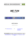
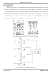
JANDS DD-8 O p t o - I s o l a t e d D M X S p l i t t e r Operating Manual Version 2.0 JANDS DD-8 DMX SPLITTER EMC COMPLIANCE This product is approved for use in Europe and Australia/New Zealand and conforms to the following standards: European Norms Australian / New Zealand Standards EN 50081-1 AS/NZS 4252.1 EN 50082-1 AS/NZS 4251.1 EN 60335-1 AS/NZS 3350.1 To ensure continued compliance with EMC Directive 89/336 and the Australian Radiocommunications Act 1992, use only high quality data cables with continuous shield, and connectors with conductive backshells. Examples of such cables are: DMX: Belden 8102 100% Aluminium foil screen, 65% Copper braid. JANDS ELECTRONICS PTY LTD 1997 All rights reserved DISCLAIMER Information contained in this manual is subject to change without notice and does not represent a commitment on the part of the vendor. JANDS ELECTRONICS P/L shall not be liable for any loss or damage whatsoever arising from the use of information or any error contained in this manual. It is recommended that all service and repairs on this product be carried out by JANDS ELECTRONICS P/L or it’s authorised service agents. JANDS lighting products must only be used for the purpose they were intended by the manufacturer and in conjunction with the user manual. JANDS ELECTRONICS P/L cannot accept any liability whatsoever for any loss or damage caused by service, maintenance or repair by unauthorised personnel, or by use other than that intended by the manufacturer. Manufactured in Australia by: JANDS ELECTRONICS PTY LTD (40 KENT RD) LOCKED BAG 15 MASCOT NSW 1460 AUSTRALIA ACN 001 187 837 PHONE: +61-2-9582-0909 FAX: +61-2-9582-0999 EMAIL: Internet: [email protected] Revision 2.0 - 5 July 1998 -2- OPERATING MANUAL JANDS DD-8 DMX SPLITTER Table of Contents Table of Contents .................................................................................... 3 1.0 Introduction........................................................................................ 4 2.0 Equipment Description ..................................................................... 5 2.1 Physical layout ................................................................................................................ 5 3.0 Getting Started .................................................................................. 6 3.1 Setting the input voltage.................................................................................................. 6 3.2 Connecting power ........................................................................................................... 6 3.3 Connecting DMX-512 input ............................................................................................ 6 3.4 Connecting DMX-512 outputs ........................................................................................ 6 3.5 Power-up sequence ......................................................................................................... 6 4.0 Operating Notes ................................................................................ 7 5.0 Technical Aspects ............................................................................. 8 5.1 Circuit Description .......................................................................................................... 8 5.2 Fault Finding Table........................................................................................................11 5.3 Miscellaneous Notes.......................................................................................................11 6.0 Installation.......................................................................................... 12 7.0 Maintenance....................................................................................... 12 8.0 Technical Specifications................................................................... 13 Appendix A Connector Pinouts ............................................................ 14 Revision 2.0 - 5 July 1998 -3- OPERATING MANUAL JANDS DD-8 DMX SPLITTER 1.0 Introduction The JANDS DD-8 is a high quality 8 channel opto-isolating data splitter specifically designed for distributing one DMX-512 input signal to eight destinations. It is designed to perform two functions - to isolate faults, and to provide signal amplification where long cable runs are used. When a fault occurs, it is possible to get high voltages in the DMX cabling. Such voltages can propagate along the cable and damage all equipment connected to that cable. The DD-8 is designed to sever the physical link between elements of the DMX system, thereby isolating faults on one line from the rest of the system. The DD-8 is fully protected against internal damage from most such faults. Since these faults can occur in all systems, the DD-8 is equally suitable for all touring, theatre, exhibition and trade show applications. In addition, including the DD-8 in a DMX system makes fault finding relatively simple. The DD-8 can also be used as a signal amplifier where extremely long cable runs are necessary, or can be used to drive more than the normal maximum of 32 devices from a console. It is recommended a DD-8 be used to isolate DMX segments that run to equipment that is powered from different supplies. Outdoor systems where the console runs from a separate supply to the dimmers are an example of such systems. The DD-8 is designed to run from most mains power systems. It will accept an input voltage from 90 to 130V, or 190 to 265V. The input voltage is set by the user at the back panel. The DD-8 is packaged in an all-steel enclosure and is designed to mount in a standard 19 inch rack. The DD-8 occupies one rack space. Revision 2.0 - 5 July 1998 -4- OPERATING MANUAL JANDS DD-8 DMX SPLITTER 2.0 Equipment Description 1 2 4 FRONT PANEL 3 5 BACK PANEL 2.1 6 Physical layout 1. DMX Input: A standard 5 pin male AXR connector for DMX-512 signal input. 2. DMX LED: This indicator shows the presence of DMX signal. 3. Power LED: This indicator shows when mains power is applied to the DD-8. 4. DMX Outputs: A standard 5 pin AXR connector outputs opto-isolated DMX-512 signal to the DMX-512 receivers. The same signal appears on all eight outputs. 5. Power input: An IEC type inlet socket connects mains power to the DD-8. 6. Fuse: The position of the fuse holder selects the mains input voltage. Refer to Section 3 for details on setting the correct mains input voltage. Revision 2.0 - 5 July 1998 -5- OPERATING MANUAL JANDS DD-8 DMX SPLITTER 3.0 Getting Started 3.1 Setting the input voltage Before applying any power it is important that the DD-8 be configured to match the incoming mains voltage. The fuse holder is marked with both “240V” and “110V” markings - the label that is the correct way up indicates which input voltage is selected. To change the input voltage, lever out the fuse holder with a flat blade screw driver and rotate it 180 degrees. Swap the fuses and re-insert the fuse holder. Note that the fuse holder is permanently attached to the socket assembly and can only be removed about 20mm. Note also that the rating of the fuse must be changed to match the input voltage. Refer to the specifications for the correct fuse rating. 3.2 Connecting power Connect a standard IEC plug and cable to the DD-8 inlet socket. When power is applied the red POWER LED will light. NOTE The DD-8 must be connected to a 3 pin earthed power source. Use of 2 pin (nonearthed) power sources will reduce the ability of the DD-8 to protect against high voltage shield faults. 3.3 Connecting DMX-512 input The DD-8 input signal should conform to the USITT DMX-512 (1990) specification. The DMX-512 input connects to the INPUT socket on the front panel. The green DMX LED will light if there is signal present. See Appendix A for connector wiring details. 3.4 Connecting DMX-512 outputs The DD-8 output signals are an amplified copy of the input signal. Connect the outputs to the DMX-512 receiving devices as required. See Appendix A for connector wiring details. 3.5 Power-up sequence When powering up, a system should be powered up in the order it appears in the DMX512 system, starting from the console and proceeding to any splitters or softpatches, and finally to the dimmers or fixtures. The DD-8 should be powered up in its appropriate position in the system. This procedure minimises the risk of producing the lighting equivalent of an audio “thump” and prevents damage to lamps, dimmers, and other controlled devices. Use the reverse procedure when powering down. Revision 2.0 - 5 July 1998 -6- OPERATING MANUAL JANDS DD-8 DMX SPLITTER 4.0 Operating Notes A DD-8 should be connected where its fault protection/isolation or fan out capability can be most effective. See Figure 4.1 below. Suggested positions include: 1. Between pieces of equipment that run from different power sources. Examples of different power sources include: • Stadium type shows where the dimmers are distributed in groups around the stadium and each group is run from a local sub-board, transformer, or sub station. In this case a separate DD-8 output should be used to drive separate dimmer groups via individual cables. If this is not practical then a DD-8 should be placed at each dimmer group, to isolate that group. • Outdoor shows where the console is run from a different power supply to the dimmers. In this case the DD-8 should be placed just before the input to the first receiving device on the line. 2. At the input to a multi-piece equipment rack. If it is necessary to have complete protection and isolation in a system then each receiving device must be connected to an individual DD-8 output. If 12 channel dimmers in racks of six are used, then one DD-8 per rack could isolate all of the dimmer inputs, provide an isolated output for the next rack’s DD-8, and still have one spare output. 3. To drive a DMX-512 control signal in multiple directions from a centre hub point. A DD-8 mounted in a truss can be used to provide drive signals for moving lights in separate segments of the truss. DMX-512 CONTROLLED DEVICES Fig. 4.1 Typical JANDS DD-8 system configuration Revision 2.0 - 5 July 1998 -7- OPERATING MANUAL JANDS DD-8 DMX SPLITTER 5.0 Technical Aspects 5.1 Circuit Description The DD-8 copies the incoming DMX-512 signal into eight identical opto-isolated outputs. A separate power supply is provided for the input and each output to maintain complete isolation. Refer to Figure 2.1 (over). The input signal is received by a standard RS485 line receiver (IC1) via protection components PTC1, PTC2, MOV1, MOV2. Note the input shield is lifted from chassis via a parallel RC network R1, C1. R4 terminates the incoming DMX line. The output of IC1 drives the opto-isolator LEDs. These LEDs are arranged in two series strings of four, and are driven via 20mA current sink transistors Q2 and Q3. The use of current sinks ensures power supply voltage fluctuations do not affect the opto drive current. The receiver output also drives the signal indicator LED L2 via positive edge detector network C8, R26, R8, D3, transistor driver Q1, and pulse lengthener C5. This circuit will respond to signals with high repetition rates, and may light in the presence of non DMX signals. Eight identical output circuits drive the DMX outputs. The opto-transistor and pull-up resistor R9 etc drive the DMX line driver directly. The line driver output is protected by PTC3, PTC4, MOV3, MOV4, etc. The output shields are tied hard to the DD-8 chassis. The DD-8 uses a custom-wound toroidal power transformer with nine separate but identical secondary windings. Each winding is used to provide an isolated linear power supply for one of the output circuits or the input circuit. A polyswitch protects each output from local overloads. The primary of the transformer is wound with a combined 240/110V winding, and the orientation of the mains fuse determines which winding is connected to the mains input. Note that when the mains voltage is changed, a fuse with the correct rating must be used. Revision 2.0 - 5 July 1998 -8- OPERATING MANUAL A B C Sec 9 Pri 120v PROTECTION DC SUPPLY 0v LED SIGNAL LED POWER A OPTO ISOLATOR POWER INLET T500mA 240V T1A 120V E N Sec 1 OUTPUT 1 PROTECTION DC SUPPLY 2 OPTO ISOLATOR 1 4/ The eight DMX output shields (pin 1) are connected directly to chassis. 3/ The DMX input shield (pin 1) is floated from earth by a 47K 1W resistor and 47nF RF bypass capacitor. 2 2/ The DMX signal pins (pins 2 & 3) are protected against continuous differential and common-mode overvoltages of up to 250 volts AC. 1/ Voltage selection is at rear fuseholder. Use M205 T500mA fuse for 220 - 240 volts, or M205 T1A fuse for 100 - 120 volts. NOTES: DMX INPUT TRANSFMR 120/240V 47nF D 47K 1 240v Sec 2 OUTPUT 2 PROTECTION DC SUPPLY File: PROTECTION Number: 3 DD8BLOK0 BLOCK DIAGRAM Date: 5-May-2000 Revision:G. HAINES Sec 8 4 4 Sheet 1 of 2 Drawn By: OUTPUT 8 PROTECTION DC SUPPLY Jands Electronics P/L 40 Kent Rd Mascot NSW 2020 Australia Ph (02) 9582-0909 OPTO ISOLATOR DD8 ISOLATEDDMX SPLITTER OUTPUT 3 H:\Lab\Dd8\Dd8blok0.sc1 Size: A4 Title OPTO ISOLATOR Sec 3 DC SUPPLY 3 A B C D A B C D 1W 47K R1 1 5pin Male AXR SH 1 - 2 + 3 DMX Input AXR1 E N L 47nF C1 MOV1 MOV2 2 7 PTC2 A870 6 1.5KE12CA 100R R4 RXE030 P1 2 A870 PTC1 C6 100nF 9x9v outputs T1 1.5KE12CA 250mA F1 Mains Input 240/110 fuse switchable 1 IC1 75176 5 8 DB101 DB1 4 1 2 3 C3 Vin 2K2 R25 2K2 R3 100nF C4 470uF 470uF C2 1 LM7805CK REG1 GND 3 3 3 10uF C7 2 1nF C8 BAV21 D2 BAV21 10K R26 BC337 Q2 R6 33R R7 33R BAV21 D3 2K2 R8 BC337 4 OPTO2 Q3 RED OPTO6 D1 R2 L2 C5 5 +5V 10uF C11 2 2 3 6N137 OPTO1 7,8 5 6 1K5 R9 GREEN SIGNAL BC337 Q1 1K 10uF 3 4 1 2 IC2 5 8 75176 6 7 MOV4 1.5KE12CA 1.5KE12CA File: Size: Number: dmxd3.sch 6 H:\Lab\Dd8\Dmxd3.sch A3 DD8 DMX ISOLATOR Title 7 Jands Electronics P/L 40 Kent Rd Mascot NSW 2020 Australia Revision: 3 Ph (02) 9582-0909 Date: 5-May-2000 Time: 10:52:32 Sheet 2 of 2 A870 PTC3 A870 PTC4 MOV3 REG2,3,4,5,6,7,8,9 DB2,3,4,5,6,7,8,9 OPTO1,2,3,4,5,6,7,8 IC2,3,4,5,6,7,8,9 7 Note: For models with serial numbers below D98xxx OPTO1 thru 8 = 6N135. R9 thru R16 selected during test for minimum skew (less than 200nsec). 100nF Vin C9 OPTO3 OPTO5 470uF 100nF 1 LM7805CK REG2 x8 channels R9,R10,R11,R12,R13,R14,R15,R16 C9,C13,C17,C21,C25,C29,C33,C37 C11,C15,C19,C23,C27,C31,C35,C39 C12,C16,C20,C24,C28,C32,C36,C40 C10,C14,C18,C22,C26,C30,C34,C38 MOV3,4,5,6,7,8,9,10,11,12,13,14,15,16,17,18 PTC3,4,5,6,7,8,9,10,11,12,13,14,15,16,17,18 P2,3,4,5,6,7,8,9 6 PWR OPTO4 C12 C10 DB101 DB2 5 L1 1K R5 OPTO7 OPTO8 +5V RXE030 P2 T1A 4 GND 3 5pin AXR FEMALE 8 1 SH 2 - DMX OUTPUT AXR2 3 + Drawn By: 8 A B C D JANDS DD-8 DMX SPLITTER 5.2 Fault Finding Table Fault Symptom Possible Cause Remedy No power indication Blown Fuse Replace fuse Mains disconnected Reconnect Ambient temperature too high Reduce ambient temperature Input cable fault Replace cable DMX source fault Repair source Faulty output cabling Replace cable Faulty receiving equipment Replace faulty receiver Control channels incorrect Check source patch settings No DMX signal indication No DMX output - One output Check receiver address settings No DMX output - All outputs Ambient temperature too high Reduce ambient temperature Faulty DD-8 output Swap cabling to another output Faulty input cabling Replace cable DMX source fault Repair source Ambient temperature too high Reduce ambient temperature Control channels incorrect Check source patch settings Check receiver address settings 5.3 Miscellaneous Notes • The protection circuitry will protect the DD-8 DMX line receiver/drivers against damage from most faults. However it is possible that extremely high fault voltages or spikes may damage the circuitry. If damage does occur it is important to re-route or repair the DMX cables as appropriate before repowering the unit. Note that the protection circuitry may take up to a minute to reset after a fault has occurred. • The internal linear power supplies are protected from faults by polyswitches. These devices become more sensitive to overload at elevated temperatures, and when tripped the unit should be switched off to enable them to reset. Allow one minute for these devices to reset once the power has been removed. • The DD-8 must be connected to a 3-pin earthed power source. Use of two pin power sources will reduce the ability of the DD-8 to protect against high voltage shield faults. Revision 2.0 - 5 July 1998 - 12 - OPERATING MANUAL JANDS DD-8 DMX SPLITTER 6.0 Installation The DD-8 is designed for mounting in standard 19 inch equipment racks. Adequate ventilation should be provided around the top of the chassis, however no blank spaces are required above or below the DD-8 specifically for ventilation of this device. Note that such spaces may be necessary to prevent the ambient temperature from rising above the maximum if other heat producing devices are mounted in the same rack. No rear mounting is necessary due to the low weight of the unit. 7.0 Maintenance WARNING DO NOT ALLOW THE ENTRY OF LIQUIDS OF ANY SORT INTO THE DD-8. With care, the DD-8 will require little maintenance. If the lexan panels require cleaning, wipe with a mild detergent on a damp soft cloth. DO NOT spray liquids onto the panels. DO NOT use solvents for cleaning the panels. Revision 2.0 - 5 July 1998 - 13 - OPERATING MANUAL JANDS DD-8 DMX SPLITTER 8.0 Technical Specifications JANDS DD-8 DMX SPLITTER SPECIFICATIONS Mains Supply: 90-130V AC, 190-265V AC, 47-53Hz, fully earthed Fuse: 110V - 1A, 240V-0.5A , M205 delay type Power consumption: 50VA maximum Operating Temperature: 45°C maximum ambient Inputs: 1 DMX Termination: 100 Ohm Outputs: 8 Isolation - input to any output: 500VAC Isolation - between outputs: 500VAC Protection - between input pins: 250VAC Protection - from input to earth: 250VAC Protection - between output pins: 250VAC Protection - from output to earth: 250VAC Construction: Zinc plated all-steel chassis Dimensions: D: 120mm Weight: 3kg Physical protection rating: IP20 Rack mounting requirements: 1 x 19” rack space / standard spacing for mounting holes W: 480mm H: 44mm No ventilation requirements No blank spaces required between units Power inlet at rear left (looking from front of unit) Power access required to replace mains fuse Revision 2.0 - 5 July 1998 - 14 - OPERATING MANUAL JANDS DD-8 DMX SPLITTER Appendix A Connector Pinouts DMX connector pin-outs 5 PIN No CONNECTION (DMX IN) CONNECTION (DMX OUTPUT) 1 RC NETWORK TO CHASSIS CHASSIS 2 IN- OUT- 3 IN+ OUT+ 4 NC NC 5 NC NC 1 4 3 2 OUTPUT DMX CONNECTOR 5 1 2 3 4 INPUT DMX CONNECTOR X MANUAL ENDS WXW Revision 2.0 - 5 July 1998 - 15 - OPERATING MANUAL JANDS DD-8 DMX SPLITTER 40 KENT RD MASCOT NSW 2020 PH: +61-2-9582-0909 FAX: +61-2-9582-0999 email: [email protected] Revision 2.0 - 5 July 1998 - 16 - OPERATING MANUAL