1
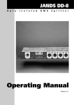
MODULE ET-MINI SMCC-547
ET-MINI SMCC-547
Module ET-MINI SMCC-547 which is STEPPING MOTOR uses fine STEPPING about 18° per each step.
This Module uses Transistor BC547 to be driver and uses LED to display operation of sending Logic “1” when Logic
“1” is controlling each phase. LED will be in status ON to display which phase is running. User must continuously send
Logic one phase by one phase and can start sending at any phase. There’s Pin INA, INB, INC and IND in this Module
for interfacing with I/O Pin of MCU and it makes MCU can send Logic “1” to control Step of phase rotation as one
phase by one phase. Its pin position’s arrangement is shown as in the picture below. In the Vcc part, it uses 5V power
supply and if using 3.3V MCU, must have OPTO to transform Logic from 3V into 5V.
C o n n e c to r S T E P P IN G M O T O R
6
STEPPING
MOTOR
P3(Brown)
Com+5V (Red)
P2(Yellow)
GND
IND
INC
INB
ETT
MiNi IO
INA
D
P4(Gray)
C
Com+5V (Red)
VCC
vcc
ET-MINI
SMCC-547
47K
1K
GND
IND
INC
INB
INA
B
47K
1K
560
BC547
47K
1K
P1(Back)
560
BC547
BC547
BC547
A
560
4001
560
47K
1K
4001
4001
4001
SMCC-PM20S-020
INPUT
Picture displays structure of ET-MINI SMCC-547 and Port Pin position.
+5V
560
P h a s e 1 (B a c k )
1K
1N4001
IN A
47K
+5V
560
P h a s e 2 ( Y e llo w )
1N4001
IN B
47K
+5V
C o m m o n (R e d )
+5V
560
P h a s e 3 (B ro w n )
Connect with STEPPING MOTOR
1K
1K
1N4001
IN C
47K
+5V
560
P h a s e 4 (G ra y )
IN D
47K
1N4001
1K
Picture displays circuit of ET-MINI SMCC-547.
ETT CO.,LTD
-1-
WWW.ETT.CO.TH
MODULE ET-MINI DC-MOTOR
ET-MINI DC-MOTOR
Module ET-MINI DC-MOTOR which is DC Motor 5V can control left and right rotate directions and can read
rotate cycle by using Opto as Sensor. The feature of using connectors and sending Logic to control rotation are shown in
the picture below. Function of IN1 connector and IN2 connector are directional controller and function of EN connector
is Enable. It runs with Logic “1”. OPA and OPB Connector send Signal Logic “1” into MCU when fan blade of DC
Motor touches Opto Sensor. If nothing touches Sensor of OPA and OPB connector, it will display as “0”. It is suitable
for reading Motor’s rotate cycle and user can select to read default values of OPA connector or OPB connector.
Table of Control DC-MOTOR
5
1
4
Q4815
10K
10K
L
150
0
1
0
1
0
GND
100uF
+ MTR -
EN
+
GND
OPB
OPA
IN2
EN
IN1
+vcc
FRB
IN1
+VCC
4001
1
1
OPB
6
EN IN1 IN2 EN IN1 IN2 EN IN1 IN2
DC-MOTOR DRIVE
ET-MINI DC-MOTOR
STOP
LEFT(L)
OPA
560
RIGHT(R)
150
IN2
L293D
560
ETT
Mini IO
Control DC MOTOR
R
MOTOR PLATE
8
x
x
Con.DC-Motor
ETT
Mini IO
+ MTR -
Picture displays structure of ET-MINI DC-MOTOR and Port Pin position.
M
-
+
5V
DC. Motor
EN
EN
Enable1
IN1
IN1
IN1
560
Left
IN2
16 Vcc
IN4
1
15
2
OUT1 3
GND
4
GND
5
OUT2
6
IN2
7
Vs
8
13
12
GND
9
Right
GND
OUT3
11
10
560
OUT4
14
IN3
Enable2
L293D
IN2
FRB
1N4001
+
-
100uF
5V
8
5V
150
Q4815
10k
1
7
2
6
3
5
4
OPA
OPA
5V
10k
5V
150
OPB
OPB
Picture displays circuit of ET-MINI DC-MOTOR.
ETT CO.,LTD
-1-
WWW.ETT.CO.TH
MODULE ET-MINI KEY 4x4
ET-MINI KEY 4x4
Module ET-MINI KEY 4x4 which is Matrix Keyboard 4x4 has 8 PIN to interface with Microcontroller. PIN1PIN4 (Column) is INPUT and MCU reads codes through key pressing and PIN5-PIN8 (ROW) is OUTPUT and MCU
sends Logic “0” to scan key in each row. MCU operation is reading status Logic of Key in each unit through PIN1PIN4. If any key is not pressed, status Logic is “1” but if any key is pressed, status Logic is “0”. Before reading status
Logic in each unit, MCU always sends Logic “0” into each key’s ROW (PIN5-PIN8). Picture below displays PIN
position and circuit.
9
0
A
B
C
D
E
F
ET-MINI
KEY4x4
NC
8
VCC
7
Pin8
6
Pin7
5
Pin6
4
Pin5
3
Pin4
2
Pin3
1
Pin2
8
Pin1
10k
ETT
Mini IO
Picture displays structure of ET-MINI KEY 4x4 and Port PIN position.
+Vcc :3V-5V
10K x 4
1
2
3
4
5
6
7
8
9
0
A
B
C
D
E
F
PIN8
PIN7
PIN6
PIN5
PIN1
PIN2
PIN3
PIN4
Picture displays circuit of ET-MINI KEY 4x4.
ETT CO.,LTD
-1-
WWW.ETT.CO.TH
MODULE ET-MINI PWR5
ET-MINI PWR5
Module ET-MINI PWR5 which is 1A Switching Regulate +5V has LED display status operation of Module.
Using this Module, must interface 7V-12V DC Output adapter with Jack connector as in the picture below. If Module
runs as normally, LED will displays as red color and then user can interface cable with OUTPUT 10 PIN Connector at
position of +VCC(+5V) and GND(0). It uses 5V OUTPUT power supply.
GND(0V)
+VCC(+5V)
1
GND(0V)
+VCC(+5V)
LM2575
LM2575-5
FR106
+
+
100uH
100uF/16V
100uF/50V
Ground Connector (0V)
FER
+5V
ET-MINI PWR5
+VCC (5V) Connector
SWITCHING REGuLATE +5V/1A
7-12VDC
+
560
+
-
W04-M
ETT
Mini IO
VIN 7-12VDC
Picture displays structure of ET-MINI PWR5 and OUTPUT Connector.
Vin
Output
GND
Feedback
ON/OFF
LM2575
1 2 3 45
+VCC(+5V)
FEEDBACK 4
+
-
7-12VDC
Bridge Diode
+
+
100uF/50V
-
1
Vin
OUTPUT
GND ON/OFF
5
3
2
FER
100uH
FR106
+
100uF/16V -
0.1u
560
Picture displays circuit of ET-MINI PWR5.
ETT CO.,LTD
-1-
WWW.ETT.CO.TH
MODULE ET-MINI SEG-A
ET-MINI SEG-A
Module ET-MINI SEG-A which is Common Anode 7-SEGMENT is interfaced with Resistor completely. So,
user can interface signal from I/O Pin of MCU with Connector below of MCU and pin position’s arrangement on
Module is shown in the picture below. Using this Module, must interface Common Pin with Vdd and must interface adp Pin with 8 Pin Port I/o of MCU. If sending Logic “0” to which Segment, that Segment will be in status ON and if
displaying number, must decode and decide to send Logic “0” to which Bit. It is easier to decode if user interfaces I/O
of MCU as same as 7-Segment’s pin arrangement.
TOS5161B
ET-MINI
ET-MINI SEG-A
SEG-A
560
560
9
10
560
560
1
2
a c e g vcc
1
2
4
b d f dp nc
560
560
560
560
9
10
COMMON ANODE
Picture above
Picture below (not use 10 Pin)
Picture displays structure of ET-MINI SEG-A and Port Pin position.
560 X 8
1.a
2.b
3.c
4.d
5.e
6.f
7.g
8.dp
Vdd
DPY_7-Seg_DP
a
DPY
b
a
c
d f g b
e
c
e
f
g
d dp
dp
Vdd
gf
ab
ed
c dp
Vdd
9.Vdd
Pin Position of 7-Segment
Picture displays circuit of ET-MINI SEG-A.
ETT CO.,LTD
-1-
WWW.ETT.CO.TH
MODULE ET-MINI SEG-K
ET-MINI SEG-K
Module ET-MINI SEG-K which is Common Cathode 7-SEGMENT is interfaced with Resistor completely. So,
user can interface signal from I/O Pin of MCU with Connector below of Module and pin position’s arrangement on
Module is shown in the picture below. Using this Module, must interface Common Pin with Ground and interface a-dp
Pin with 8 Pin Port I/O of MCU. If sending Logic “1” to which Segment, that Segment will be in status ON and if
displaying number, must decode and decide to send Logic “1” to which Bit. It is easier to decode if user interfaces I/O
of MCU as same as 7-Segment’s pin arrangement.
ET-MINI SEG-K
TOS5161A
560
560
560
560
9
10
1
2
560
560
a c e g nc
1
2
5
560
560
9
10
b d f dp gnd
COMMON CATHODE
Picture above
Picture below (not use 9 Pin)
Picture displays structure of ET-MINI SEG-K and Port Pin position.
560 X 8
1.a
2.b
3.c
4.d
5.e
6.f
7.g
8.dp
DPY_7-Seg_DP
GND
a
DPY
b
a
c
d f g b
e
e
c
f
g
d dp
dp
GND
gf
ab
ed
c dp
GND
10.GND
Pin position of 7-Segment
Picture displays circuit of ET-MINI SEG-K.
ETT CO.,LTD
-1-
WWW.ETT.CO.TH
MODULE ET-MINI 232-TTL2
ET-MINI 232-TTL2
Module ET-MINI 232-TTL2 which is RS232 Communication Line Driver uses 5V power supply. It transforms TTL signal of
MCU into RS232(±12V). There’s 2 channels for using. Firstly, Connector on Input side, must interface Tx PIN and Rx PIN with Tx PIN
and Rx PIN of MCU respectively. User must interface Tx PIN and Rx PIN in the same channel (Tx0:Rx0, Tx1:Rx1). In the part of +VCC
PIN and GND PIN, must interface with power supply of MCU. Secondly, Connector on Output side, uses the same channel as Input side
and then interfaces Rx PIN with Tx PIN and interfaces Tx PIN with Rx PIN of communicate device. Finally, interfaces GND PIN with
GND PIN of communicate device but in the part of +VCC, does not interface its.
RS232-0
RS232-1
RS232-0
0.1
RS232-1
GND
TX1
RX1
TX0
+
RX0
+
+VCC
+
+VCC
RXD1
TXD1
GND
+VCC
RXD0
TXD0
GND
+VCC
RXD
TXD
GND
+VCC
RXD
TXD
GND
2
+
Connector on side of Output CH0 and CH1
MAX232
TTL +5V RS232-LINE DRIVER
ET-MINI 232-TTL2
GND
TX1
RX1
TX0
RX0
+VCC
Connector on Input side
ETT
Mini IO
Picture displays structure of ET-MINI 232-TTL2 and Port PIN position.
+VCC=5V
16 VCC
+
10uF
10uF
2
6
RS232-0
VCC
RXD0
TXD0
GND
+
C1+ 1
V+
V-
C1- 3
4
C2+
10uF
10uF
15 GND
13 R1I
14 T1O
8 R2I
7 T2O
+
C2- 5
12
R1O
11
T1I
9
R2O
10
T2I
+
RX0
TX0
RX1
TX1
MAX232
RS232-1
VCC
RXD1
TXD1
GND
Picture displays circuit of ET-MINI 232-TTL2.
ETT CO.,LTD
-1-
WWW.ETT.CO.TH
MODULE ET-MINI 232-TTL3
ET-MINI 232-TTL3
Module ET-MINI 232-TTL3 which is RS232 Communication Line Driver uses 3V-5V power supply. It
transforms TTL signal of MCU into RS232(±12V). There’s 2 channels for using. Firstly, Connector on Input side, must
interface Tx PIN and Rx PIN with Tx PIN and Rx PIN of MCU respectively. User must interface Tx PIN and Rx PIN in
the same channel (Tx0:Rx0, Tx1:Rx1). In the part of +VCC PIN and GND PIN, must interface with power supply of
MCU. Secondly, Connector on Output side, uses the same channel as Input side and then interfaces Rx PIN with Tx PIN
and interfaces Tx PIN with Rx PIN of communicate device. Finally, interfaces GND PIN with GND PIN of
communicate device but in the part of +VCC, does not interface its.
RS232-1
RS232-0
0.1
0.1
GND
TX1
RX1
TX0
RX0
0.1
0.1
RS232-0
Connector on side of Output CH0 and CH1
+VCC
0.1
RS232-1
+VCC
RXD1
TXD1
GND
+VCC
RXD0
TXD0
GND
+VCC
RXD
TXD
GND
+VCC
RXD
TXD
GND
4
ADM3232
ADM3232
TTL +3V/5V RS232-LINE DRIVER
ET-MINI 232-TTL3
GND
TX1
RX1
TX0
RX0
+VCC
ETT
Mini IO
Connector on Input side
Picture displays structure of ET-MINI 232-TTL3 and Port PIN position.
+VCC=3V-5V
16 VCC
C1+ 1
0.1uF
0.1uF
2
6
V+
V-
C1- 3
4
C2+
0.1uF
0.1uF
RS232-1
VCC
RXD1
TXD1
GND
15 GND
13 R1I
14 T1O
8 R2I
7 T2O
RS232-0
ETT CO.,LTD
VCC
RXD0
TXD0
GND
C2- 5
12
R1O
11
T1I
9
R2O
10
T2I
RX1
TX1
RX0
TX0
ADM3232
Picture displays circuit of ET-MINI 232-TTL3.
-1-
WWW.ETT.CO.TH
MODULE ET-MINI 74HC595
ET-MINI 74HC595
Module ET-MINI 74HC595 is 8 Bit Serial-IN, Serial or Parallel-OUT Shift Register. It can test MCU’s SPI
communication and its features of Module and Connector display in picture below. When using SPI communication, we
use DIN Connector to receive Serial data from MCU (interfaced with MOSI of MCU). LATCH Connector is interfaced
with I/O PIN of MCU. It runs at edge rising time of Clock (from 0 to 1)and it delivers Parallel data through 10 PIN
Connector in Output Logic side of Module. CLOCK Connector runs at edge rising time and interfaces with SCLK PIN
of MCU(SPI). Signal CLOCK that is received from MCU, we use its for Shift 8 Bit data that is entered per time. DOUT
Connector is Output PIN for sending Serial data and 10 PIN Connector is Output PIN for sending Parallel data.
[2]
[0]
[5]
[3]
[1]
OUTPUT LOGIC
[4]
[7]
[G]
0.1
Data Parallel Output Connector
GND
DOUT
CLOCK
LATCH
DIN
+VCC
SPI/Serial to Parallel 8-BIT
GND
DOUT
CLOCK
LATCH
DIN
+VCC
ET-MINI
74HC595
[6]
[V]
8
[1]
[3]
[5]
[7]
[G]
OUTPUT LOGIC
[0]
[2]
[4]
[6]
[V]
74HC595
ETT
Mini IO
Connectoron Input Side
Picture displays structure of ET-MINI 74HC595 and Port Pin position.
+VCC=5V
OUTPUT LOGIC
OUT0
OUT1
OUT2
OUT3
OUT4
OUT5
OUT6
OUT7
3 Q3
4 Q4
VCC 16
15
Q0
14
DS
OE 13
5 Q5
6 Q6
ST_CP 12
SH_CP 11
1 Q1
2 Q2
7
8
DIN
LATCH
CLOCK
10
Q7
MR
GND
Q7’ 9
DOUT
74HC595
Picture displays circuit of ET-MINI 74HC595.
ETT CO.,LTD
-1-
WWW.ETT.CO.TH
MODULE ET-MINI DS1307
SDA
SCL
INT
SDA
SCL
INT
ET-MINI DS1307
Module ET-MINI DS1307 which is Real Time Clock (RTC) I2C displays Time Base such as Clock, Timer, and
Calendar. There’s SDA Connector and SCL Connecter for interfacing with SDA PIN and SCL PIN of MCU
respectively and for external INT Connector interfaces with MCU when uses Interrupt. It uses VDC 3V-5V power
supply and this I2C No. has Control Byte “1101000X”. Moreover, there’s battery box to back UP Time Base correctly
when Module is not supplied power.
Using this Module, firstly, Set Jumper SDA, SCL and INT and place on ENA side as in the picture. It interfaces
R Pull Up with all 3 PIN of I2C. If interface R Pull Up with 3 PIN of I2C. If R Pull Up is interfaced in Line SDA and
SCL from external or is interfaced from other Module, must Set Jumper of all 3 PIN and place on DIS side because it
does not interface R Pull Up once.
DIS/ENA
3V
DIS/ENA
1
SDA
SCL
INT
DS1307
1101000x
0.1
Set Jumper when not interface with R Pull Up
GND
SDA
SCL
INT
+VCC
DIS/ENA
10K
10K
10K
BAT 3V
+
I2C/RTC DS1307
32.768KHz
ET-MINI
DS1307
GND
SDA
SCL
INT
+vcc
Set Jumper when interface with R Pull Up
ETT
Mini IO
Picture displays structure of ET-MINI DS1307 and Port PIN position.
DIS/ENA
SDA
SCL
INT
+VC C =5V
8
7
1
2
SDA
SCL
SQW/OUT
VCC
10K x 3
6
SD A
SC L
IN T
5
4
GND
3
Vbat
X2
X1
DS1307
3V
32.768KH z
Picture displays circuit of ET-MINI DS1307.
ETT CO.,LTD
-1-
WWW.ETT.CO.TH
MODULE ET-MINI PCF8583
ET-MINI PCF8583
Module ET-MINI PCF8583 which is Real Time Clock (RTC) I2C displays Time Base such as Clock, Timer,
and Calendar. Moreover, it can adapt to be Counter for external Clock. There’s 2 Modes that are Mode RTC and Mode
Counter. When using Mode RTC, there’s C adjustment for Frequency Crystal. It makes Crystal create frequency
correctly and get accurate Time Base. There’s battery box to back up I2C because it makes Time Base can run
continuously, otherwise there’s no power supply into Module. When using Mode Counter(CNT), there’s pulse
Connector that can input Pulse signal from external generator into I2C. Moreover, there’s SW COUNT that can create
pulse signal by self.
Control Byte of I2C Module is assigned as 101000[1]x. Interface SDA Connector and SCL Connector with
SDA PIN and SCL PIN of MCU respectively. In case of not use INT Connector, it is not necessary to interface its but in
case of using this connector, must interface INT connector with PIN of MCU that is assigned to receive INT signal. In
part of +VCC PIN and GND PIN interface with power supply of MCU instantly.
3
DIS/ENA 10K 101000[1]x
SDA
10K
SCL
0-30pF
INT
3V
10K
GND
SDA
ET-MINI
PCF8583
1N60
CNT
10K
I2C RTC/PCF8583
GND
SDA
SCL
INT
+VCC
0.1
SW COUNT
SCL
RTC
1N60
INT
EXT
PULSE
32.7KHz
+VCC
0.1
VBAT
+
PCF
8583
ETT
Mini IO
Pin Connector’s arrangement On Input side.
Picture displays structure of ET-MINI PCF8583 and Port PIN position.
Using this I2C Module, there’s 2 points to Set Jumper. Firstly, it is at Jumper DIS/ENA point, must Set Jumper
SDA, SCL and INT on ENA side. It interfaces R Pull Up with I2C PIN of SDA, SCL and INT. In case of interface R
Pull Up from external or other Module I2C in Line of SDA and SCL, it is not necessary to interface R Pull Up once.
User only Set Jumper all 3 of them on DIS side and R Pull Up will be taken off as in the picture below.
ETT CO.,LTD
-1-
WWW.ETT.CO.TH
MODULE ET-MINI PCF8583
SDA
SCL
INT
SDA
SCL
INT
DIS/ENA
DIS/ENA
Set Jumper when interface with R Pull Up
Set Jumper when not interface with R Pull Up
Secondly, it is at RTC/CNT point. It chooses mode operation of I2C. In case of using Mode RTC, must Set
Jumper on RTC side. It interfaces Crystal Pin with OSCI Pin. In case of using Mode Counter, must Set Jumper on CNT
side. It interfaces Pin that receives Pulse signal from external and from SW Counter with OSCI Pin of I2C as in the
picture below.
RTC
RTC
CNT
Set Jumper when using I2C to be RTC
CNT
Set Jumper when using I2C to be to be Counter
SDA
SCL
INT
+VCC=3V-5V
DIS/ENA
10K x 3
1
SDA
SCL
INT
7
SDA
SCL
INT
5
6
PCF8583P
2
3
4
VSS
8
A0
VBAT
+3V
OSCO
+
-
101000[1]x
OSCI
VDD
1N60x2
EXE
PULSE
+Vcc=3V-5V
32.768KHz
0-30pF
RTC
CNT
SW. Counter
10K
0.1u
Picture displays circuit of ET-MINI PCF8583.
ETT CO.,LTD
-2-
WWW.ETT.CO.TH
MODULE ET-MINI PCF8574
ET-MINI PCF8574
Module ET-MINI PCF8574 is 8 Bit I2C Port I/O expansion for Microcontroller. There’s 2 Module No. and both
Module No.PCF8574 and Module No.PCF8574A are replaceable. Both of them have the same specifications but some
Control Byte are only differently. Using this Module, interface SDA Connector and SCL Connector of Module with
SDA PIN and SCL PIN of MCU respectively. In part of +VCC and GND can interface with power supply of MCU
instantly. This I2C No. uses 2.6V-6.0V power supply. It is not necessary to interface INT PIN, in case of not using its.
Port on Output side of I2C must interface with 10 PIN Connector and feature of PIN arrangement is displayed in picture
below. It can interface to control I/O device that uses less power supply such as LED.
[6]
[4]
[2]
[0]
[G]
[7]
[5]
[3]
[1]
OUTPUT LOGIC
[V]
2
[1]
[3]
[5]
[7]
[G]
10 PIN Connector arrangement on Output side
PCF8574
GND
SDA
SCL
INT
I2C INPUT/OUTPUT
ET-MINI PCF8574
GND
SDA
SCL
INT
A0
A1
A2
+vcc
LO / HI
+vcc
0.1
10K
10K
10K
ET-MINI
PCF8574
OUTPUT LOGIC
[0]
[2]
[4]
[6]
[V]
DIS/ENA
SDA
10K
SCL
10K
INT
10K
PCF8574 = ID:0100[A]X
PCF8574A = ID:0111[A]X
ETT
Mini IO
Pin Connector arrangement on Input side
Picture displays structure of ET-MINI PCF8574 and Port PIN position.
Using this I2C Module, there’s 2 points to Set Jumper. Firstly, it is at Jumper ENA/DIS point, must Set Jumper
SDA, SCL and INT on END side. It interfaces R Pull Up with I2C PIN of SDA, SCL and INT. In case of interface R
Pull Up from external or other Module I2C in Line of SDA and SCL, it is not necessary to interface R Pull Up once.
User only Set Jumper all 3 of them on DIS side and R Pull Up will be taken off as in the picture below.
DIS/ENA
DIS/ENA
SDA
SCL
INT
SDA
SCL
INT
Set Jumper when interface with R Pull Up
ETT CO.,LTD
Set Jumper when not interface with R Pull Up
-1-
WWW.ETT.CO.TH
MODULE ET-MINI PCF8574
Secondly, it is at LO/HI point. It chooses position address for I2C and user can Set Jumper as required. Then
combine default value of position address and Control Byte of I2C together because it can control I2C No. correctly. If
Set Jumper on Lo side, Address PIN is “0”, and if Set Jumper on HI side, Address PIN is “1” as an example in the
picture.
LO / HI
LO / HI
A0
A1
A2
A0
A1
A2
Set Jumper A0,A1,A2 = 000
Set Jumper A0,A1,A2 = 111
DIS/ENA
SDA
SCL
INT
10Kx3
INT
SCL
SDA
9
P4
10
P5
11
P6
12
P7
13
INT
14
SCL
15
SDA
16
VDD
VSS
8
6 P2
7 P3
4 P0
5 P1
1 A0
2
A1
3 A2
PCF8574/AP
10Kx3
OUT7
OUT6
OUT5
OUT4
OUT3
OUT2
OUT1
OUT0
OUTPUT LOGIC
PCF8574 = ID:0100[A]X
PCF8574A = ID:0111[A]X
+VCC=5V
LO/HI
A0
A1
A2
Picture displays circuit of ET-MINI PCF8574/AP.
ETT CO.,LTD
-2-
WWW.ETT.CO.TH
MODULE ET-MINI 24xx
ET-MINI 24xx
Module ET-MINI 24xx which is I2C E2PROM 24xx family collects data. There’s 4 Modules, so user can
communicate which Module. Each Module has different address and shows on board, so user must select correct
address for using Module.
Using this Module, must select Set Jumper SDA and SCL to place in ENA side and then interface R Pull UP
with SDA PIN and SCL of I2C. If R Pull UP is interfaced from external in Line of SDA and SCL or from other Module
I2C, it is not necessary to interface R Pull Up once. In this case, only interface both Set Jumper to place in DIS side for
taking off R Pull Up from SDA PIN and SCL of I2C in Module.
In part of Module Connector, interface SDA Connector with SDA PIN of MCU and also interface SCL
Connector with SCL PIN of MCU and then user can read and write this E2Prom No. In this case, user must have
knowledge of using this E2Prom No. because can control its writing and reading correctly.
ENA / DIS
SDA
10K
10K
SCL
ENA / DIS
10
1010100x
1010101x
0.1
0.1
24xx
SDA
24xx
SCL
1010111x
1010110x
0.1
0.1
24xx
24xx
Picture displays Set Jumper when it does not interface with R Pull Up.
I2C-Serial EEPROM
GND
SDA
SCL
+vcc
ET-MINI
24xx
ENA / DIS
ETT
Mini IO
SDA
GND
SDA
SCL
+VCC
SCL
Picture displays Set Jumper when it interfaces with R Pull Up.
Picture displays position of Module Connection.
Picture displays structure of ET-MINI 24xx, Port Pin position and Set Jumper.
ETT CO.,LTD
-1-
WWW.ETT.CO.TH
MODULE ET-MINI 24xx
10K
+vcc = 5V
+vcc = 5V
ENA/DIS
SDA
SCL
10K
5
24xx
VSS
4
SDA
3
SCL
2
A2
1
6
5
ID:1010101x
6
SDA
WP
7
SCL
8
A1
4
VSS
3
A2
2
A1
A0
1
VCC
5
A0
6
24xx
ID:1010100x
7
SDA
WP
8
SCL
VCC
+Vcc=5V
SCL
SDA
SDA
VCC
WP
6
5
8
7
A0
2
A1
1
ID:1010110x
4
VSS
3
A2
2
A1
A0
1
24xx
3
4
VSS
24xx
A2
WP
7
SCL
VCC
8
ID:1010111x
+vcc=5V
+vcc = 5V
Picture displays circuit of ET-MINI 24xx.
ETT CO.,LTD
-2-
WWW.ETT.CO.TH
MODULE ET-MINI 422/485
ET-MINI 422/485
Module ET-MINI 422/485 which is Line Driver transform TTL Signal of CPU into Balance Line for
sending/receiving signal in the same Balance Line. This Module can use as RS232 and RS485 communication. In case
of using RS232 communication, it uses 2 IC Line Drivers and in case of using RS485 Communication, it uses 1 IC Line
Driver. It usually communicate in Network type and method for using Module is ;
1. Using RS422 Communication : Connector on Input side of Module, must interface RX Connector and TX connector
with RX PIN and TX PIN of MCU respectively and then interface +5V power supply. Then Set Jumper near IC Line
Driver and place on RS422 side and FULL side as in the picture. In this case, we do not use DIR Connector.
RS422
HALF
RS485
FULL
Picture displays Set Jumper when using RS422 Communication.
For Connector on Output side of Module, must interface with RS422 communicative device. It uses 4 cables
and then interface T(+) PIN and T(-) PIN of Module with R(+) PIN and R(-) PIN of communicative device respectively.
After that interface R(+) PIN and R(-) PIN of Module with T(+) PIN and T(-) PIN of communicative device
respectively.
2. Using RS485 Communication : Connector on Input side of Module, must interface RX Connector and TX connector
with RX PIN and TX PIN of MCU respectively and then interface +5V power supply. In this case, we use DIR
Connector by interfacing its with I/O PIN of MCU, after that MCU sends Logic to control sending/receiving interval of
IC Line Driver. If DIR Pin is Logic “1”, IC Line Driver will be sender and if DIR Pin is Logic “0”, IC Line Driver will
be recipient. Then Set Jumper near IC Line Driver and place on RS485 side and HALF side as in the picture below.
RS422
HALF
RS485
FULL
Picture displays Set Jumper when using RS485 Communication.
For Connector on Output side of Module, must interface with RS485 communicative device. It uses 2
cables and then interface T(+) PIN and T(-) PIN of Module with T(+) PIN and T(-) PIN of communicative device.
Using this method, must control one communication is sender and other one communication is recipient but one
communication can not be both sender and recipient in the same time. In this case, we do not use R(+) PIN and R(-) PIN
of Module.
Jumper RZ, RH, RL and TZ, TH, TL, we Set them for interfacing R Pull UP with Line on Output side. It
makes RS422 and RS485 Communication can send/receive signal a longer distance. The feature of Set Jumper is in the
picture below.
ETT CO.,LTD
-1-
WWW.ETT.CO.TH
MODULE ET-MINI 422/485
RZ
RH
RL
TZ
TH
TL
Picture displays Set Jumper to interface R Pull Up because it makes communication a longer distance.
RX422
TX422
RS485
T(+)T(-) R(+)R(-)
5
RX422
Connector on Output side
GND
RX
TX
DIR
+VCC
1K
120
1K
0.1
RX422
75176
RS485 HALF
FULL
GND
RX
TX
DIR
+VCC
ET-MINI
422/485
RZ
RH
RL
1K
120
1K
0.1
RS485
TX422
RS422
TTL +5V RS422/485 LINE DRIVER
TZ
TH
TL
TX422
RX/485
75176
T (+ ) T (-)R (+ ) R (-)
Connector on Input side
ETT
Mini IO
Picture displays structure of ET-MINI 422/485 and Port Pin position.
1K
TL
1K
RS485
TX422
VCC = 5V
1
RS422
3
RS485
4
TX
VCC
R
RE
DE
D
SN75176
2
DIR
VCC = 5V
B
A
GND
120
8
TH
VCC
TZ
7
T(+)
6
5
T(-)
HALF
R(+)
VCC = 5V
RX
1
FULL
NC
4 D
SN75176
R
2 RE
3 DE
VCC 8
B 7
A
GND
RX422
R(-)
6
5
1K
RL
1K
120
RH
VCC
RZ
Picture displays circuit of ET-MINI 422/485.
ETT CO.,LTD
-2-
WWW.ETT.CO.TH
MODULE ET-MINI 3T05 TTL
GND
OUT7
OUT5
+VOUT
OUT6
9
OUT4
OUT2
GND
+VOUT
OUT0
OUTPUT
OUT3
OUT1
ET-MINI 3T05 TTL
Module ET-MINI 3T05 TTL which is OPTO to transform level of Logic from 3V into 5V or from 5 V into 3V
has 8 channels. It uses with MCU that uses 3.3V power supply to drive or load with 5V power supply. All 8 channels of
this Module can use as 2 types; only Input or only Output but can not use as both Input/Output in the same time. Its
proceedings are ;
1). It is external INPUT for receiving signal Logic 5V into MCU that can receive Logic 3.3V, interface 5V
power supply with +VIN Connector and Ground with GND of Module respectively and then interface Input [0..7] with
connector for sending signal into MCU. In Output part of Module, interface 3.3V power supply with +VOUT Connector
and Ground with GND of Module respectively and then interface Output [0…7] Connector with I/O Pin of MCU.
2). It is OUTPUT for sending signal Logic 3.3V from MCU to control external device that can receive Logic
5V, interface 3.3V power supply with +VIN Connector and Ground of MCU with GND of Module respectively and
then interface Input [0..7] with I/O Pin of MCU. In Output part of Module, interface external 5V power supply with
+VOUT Connector and external Ground with GND of Module respectively and then interface Output [0…7] Connector
with controller device.
IN7
IN6
OUT6
OUT7
GND
GND
1K
PC817
560
IN7
1K
PC817
560
IN6
GND
IN5
IN4
1K
PC817
560
IN3
IN4
IN5
IN3
IN2
1K
PC817
560
IN2
IN1
IN0
1K
PC817
560
+VOUT
OUT0
OUT1
OUT2
OUT3
OUT4
OUT5
1K
PC817
560
IN0
IN1
1K
PC817
560
INPUT
+VIN
ET-MINI
3T05 TTL
GND
+VIN
01 23 45 67
Connector in side of OUTPUT
+VIN
1K
PC817
560
01 23 4 567
Connector in size of INPUT
Picture displays structure of ET-MINI 3TO5 TTL and Port PIN position .
ETT CO.,LTD
-1-
WWW.ETT.CO.TH
MODULE ET-MINI 3T05 TTL
+VOUT
+VIN
560 x8
PC817
1k x8
IN0
OUT0
IN1
OUT1
IN2
OUT2
IN3
OUT3
IN4
OUT4
IN5
OUT5
IN6
OUT6
IN7
OUT7
Picture displays circuit of ET-MINI 3TO5 TTL.
ETT CO.,LTD
-2-
WWW.ETT.CO.TH
User Manual For ET-MINI AUDIO OUT
ET-MINI AUDIO OUT
It is a mini amplifier with speaker that receives Input
as Analog audio signal type and sends audio signal out through
speaker. Moreover, there is Stereo Jack that can be interfaced
with headphone or external amplifier.
Specifications of Board ET-MINI AUDIO OUT
• Mini Speaker Model PB-2015
• Receive signal as Analog Input
• Auto-cut audio of speaker PB-2015 on board when Stereo
Jack is inserted.
• IC LM386 is designed to be circuit amplifier
- 1-
www.ett.co.th
User Manual For ET-MINI LOGIC LEVEL SHIFTER
ET-MINI LOGIC LEVEL SHIFTER
The connection Logic Voltage between 3.3V and 5V
ET-MINI LOGIC LEVEL SHIFTER is a circuit for connection
signal Logic between +5V device and 3.3V device (or 3V) by
using IC Buffer 74LXX245. Specifications of this IC run with
Voltage 3.3V but it can support Voltage Input up to 5V, so we
can use it to be Buffer of Voltage from 3.3V to 5V.
Specifications of ET-MINI LOGIC LEVEL SHIFTER
•
•
•
•
Can send signal Logic 5V to be signal Logic 3.3V
8 Channels for connection
Can configure directions of signal
IC Regulator 3.3V/500mA for supplying power into 3.3V
device
- 1-
www.ett.co.th
User Manual For ET-MINI LOGIC LEVEL SHIFTER
**NOTE**
Regulator 3.3V/500mA is provided internal circuit, so
we only supply power into Connector 5+5V and Voltage 3.3V
at Connector 3V3 can supply power into external devices.
If external device has already had 3.3V power supply, we
must interface GND only and should not interface external
Voltage with +3V3 internal board because circuit maybe
damaged.
Applications
We can divide it into groups of application as follows;
1. Connection as only one direction type from 5V device into
3.3V device.
We must set Jumper DIR on the position A-TO-B, Logic
5V must be interfaced on A side and Logic 3.3V must be
interfaced on B side. Signal Logic 5V on A side is sent
through Buffer to be Logic 3.3V on B side.
- 2-
www.ett.co.th
User Manual For ET-MINI LOGIC LEVEL SHIFTER
2. Connection as only one direction type from 3.3V device
into 5V device.
We must set Jumper DIR on the position B-TO-A, Logic
5V must be interfaced on A side and Logic 3.3V must be
interfaced on B side. Signal Logic 3.3V on B side is sent
through Buffer to be Logic of device on A side. Voltage
that is sent into A device is 3.3V and it is enough for A
device to know Logic “1” and “0”.
+3V3
B-TO-A
A-TO-B
+3V3
Device 5V (A)
VCC
Din0
Din1
Din2
Din3
Din4
Din5
Din6
Din7
GND
DIR
+5V
+5V
A0
A1
A2
A3
A4
A5
A6
A7
GND
1
2
3
4
5
6
7
8
9
10
DIR
VCC
20
A0
A1
A2
A3
A4
A5
A6
A7
E
19
B0
B1
B2
B3
B4
B5
B6
B7
18
17
16
15
14
13
12
11
+3V3
Device 3.3V (B)
+3V3
B0
B1
B2
B3
B4
B5
B6
B7
GND
VCC
Dout0
Dout1
Dout2
Dout3
Dout4
Dout5
Dout6
Dout7
GND
GND
- 3-
www.ett.co.th
User Manual For ET-MINI LOGIC LEVEL SHIFTER
3.
Connection as bi-direction type between
3.3V device and 5V device.
From the circuit above, it is the connection signal Logic
between 5V device and 3V device. We must interface signal Pin
Output of A device with signal Pin Input of B device and then
interface signal Pin Output of B device with signal Pin Input
of A device. To configure directions of IC 74LXX245 must n=be
configured all 8 bit and we can configure in each bit, so if
we must connect signal of both sender and receptor (both 3.3V
device and 5V device), we must configure DIR to be A-TO-B as
in the example circuit above.
Example: The connection signal between Microcontroller (5V
device) and SD/MMC CARD (3V device) by using ET-MINI SD/MMC in
SPI MODE.
- 4-
www.ett.co.th
User Manual For ET-MINI LOGIC LEVEL SHIFTER
SD/MMC
SOCKET
74LXX245
- 5-
www.ett.co.th
User Manual For ET-MINI SD/MMC
ET-MINI SD/MMC
The connection SD/MMC MEMORY CARD
ET-MINI SD/MMC is a device for connection components with
SD/MMC memory Card; for example, the connection between
Microcontroller and Memory Card (SD/MMC). This set contains
Socket for inserting Memory Card such as SD and MMC and it
provides external signal Pin at Connector Pin, so it is quite
convenient to apply. Moreover, there are many circuits such as
Circuit Card Detect, Circuit Pull-Up and etc.
Specifications of ET-MINI SD/MMC
• Support Memory Card as SD type and MMC type
• Can select Enable/ Disable for Circuit Pull-Up
• Can display status of inserting Card or CARD DETECT by
using LED and send signal OUTPUT through Pin signal CD.
There is specification as follows;
CD = 1; It means that there is no Card.
CD = 0; It means that there is Card.
• Can display status of Switch Write Protection on SD/MMC
Card and send signal OUTPUT through signal Pin WP as
follows;
WP = 1; It is OFF position of Switch Write
Protection.
WR = 0; It is ON position of Switch Write Protection.
- 1-
www.ett.co.th
User Manual For ET-MINI SD/MMC
Example: The connection signal between Microcontroller (5V
device) and SD/MMC CARD (3V device) by using ET-MINI LOGIC
LEVEL and ET-MINI SD/MMC in SPI Mode.
- 2-
www.ett.co.th
User Manual For ET-MINI SD/MMC
SD/MMC
SOCKET
74LXX245
Details of Signal Pin SD CARD
There are 2 proceedings to connect SD CARD; SD MODE type
and SPI MODE type as the details in the table below.
-
Details of signal Pin when it is connected as SD MODE
type.
- 3-
www.ett.co.th
User Manual For ET-MINI SD/MMC
-
Details of signal Pin when it is connected as SPI MODE
type.
Details of Signal Pin MMC CARD
There
are
2
proceedings
to
connect
MMC
CARD;
MultiMediaCard MODE and SPI MODE as the details in the table
below;
-
Details of signal Pin when it is connected as
Multimedia Card Mode type.
-
Details of signal Pin when it is connected as SPI Mode
type.
- 4-
www.ett.co.th
User Manual For ET-MINI SD/MMC
- 5-
www.ett.co.th
User Manual For ET-MINI MP3
ET-MINI MP3
Board ET-MINI MP3 is a MP3 Decoder to convert signal into
voice. ETT uses IC VLSI No.VS1002D to decode file MP3 and to
be the permanent IC on board. VS1002D is the IC MP3 Decoder
that is one of the highest quality and the easiest
application. It can decode File MP3 and File WAVE instantly
and there is Analog OUTPUT to be Stereo audio type, so we can
connect
it
with
headphone
or
amplifier
instantly.
Additionally, we can connect with Microcontroller easily by
using SPI Serial Port standard. So, we can apply ET-MINI MP3
with Microcontrollers as desired.
The structural feature of Board ET-MINI MP3 is just a
part of basic circuit VS1002D because it is not applied to be
processed MP3 Player or connect with any version of Board
Microcontroller but Board ET-MINI MP3 can apply with other
project works independently.
Concept of circuit is designed
to connect VS1002D with necessary components such as circuit
amplifier with Jack Stereo, it is quite convenient to connect
with headphone or amplifier; and circuit Pre-Amplifier to
receive signal from Microphone as Condenser type and including
to circuit Crystal Oscillator Generator. Circuit VS1002D is
arranged to be ready to active but there is no signal
controller only. In the part of signal controller, there is
Connector to connect with external microcontroller easily.
ETT CO.,LTD
-1-
WWW.ETT.CO.TH
User Manual For ET-MINI MP3
Specifications of Board ET-MINI MP3
• IC MP3 Decoder of VLSI No.VS1002D
• Be able to decode File MPEG that accesses decoder as MPEG
1.0 & 2.0 Audio layer III (CBR + VBR) and including of
WAV and PCM
• Be able to access decode audio signal from Microphone to
be standard ADPCM data
• Support Streaming Data for File MP3 or WAVE.
• Be able adjust Bass Control
• Active with signal Clock 12.288 MHz and can use X2 Mode
internal PLL
• There is circuit to convert data into high quality of DAC
voice with stereo Amplifier. We can connect Audio Out
with amplifier or standard stereo headphone that has
Impedance value about 30Ω instantly. Connector Audio Out
of Board uses high quality Jack Stereo that can be
interfaced with headphone or amplifier of computer PC
instantly.
• Active with DC Voltage from 2.5V to 3.6V with LED to
display status of Power and Zener Diode to protect over
voltage
• Support connection between signal and Microcontroller
through SPI Serial Port
• Be able to modify operation of board to be MP3 player as
Standalone type without using the any controller from
Microcontroller (see more information from “Application
Note” of VLSI)
• Board size 4.4 x 5.6 cm.
Applications for Board ET-MINI MP3
We can apply Board ET-MINI MP3 for many types, especially
the
connection
with
Microcontroller.
We
can
configure
preferred conditions by self from program controller that is
developed. We can apply it by using memories components such
as SD/MMC or others to save File data for sending into VS1002D
to decode and convert into voice. In this case, we do not
mention about the memory management and File systems, so user
must study and learn more information by self.
The well-known and easiest proceeding to connect Board
ET-MINI MP3 with Microcontroller is connecting with SPI Serial
Port. If Microcontroller is active with power supply from
+2.5V to +3.3V, we can connect signal between Microcontroller
ETT CO.,LTD
-2-
WWW.ETT.CO.TH
User Manual For ET-MINI MP3
and IC VS10002D of Board ET-MINI MP3 instantly; on the other
hand, if Board Microcontroller is active with power supply
+5V, we must find circuit to convert Logic +5V into Logic
+3.3V first. ETT designs Board “ET-MINI LOGIC LEVEL SHIFTER”
to support this application as shown in the diagram below.
Figure displays the connection between board ET-MINI MP3 and
Microcontroller that uses +5V Power Supply.
ETT CO.,LTD
-3-
WWW.ETT.CO.TH
1
2
3
4
10nF
10nF
27
L
R
27
G
AUDIO OUT
27
D
D
10nF
+3V3
+3V3
+3V3
1K
VS1002D
+3V3
+3V3
LEFT
RIGHT
GBUF
46
39
42
1K
DGND1
DGND2
DGND3
DGND4
DGND5
1
2
+3V3
XCS#
SCLK
SI
BSYNC
RES#
SO
DREQ
RX
TX
xCS
SCLK
SI
BSYNC/xDCS
xRESET
SO
DREQ
RX
TX
AVDD3
AVDD2
AVDD1
RCAP
45
43
38
44
100K * 4
33pF
XTALO
AGND4
AGND3
AGND2
AGND1
1M
12.288 MHz
47
41
40
37
33pF
Title
A
Size
A4
Date:
File:
1
2
B
1K
17
18
GPIO0
GPIO1
GPIO2
GPIO3
TEST
GPIO0
GPIO1
GPIO2/DCLK
GPIO3/SDATA
MICROPHONE
-
1K
0.1uF
32
33
34
9
10
XTALI
0.1uF
+
1 uF
+3V3
B
10 uF
PWR
23
28
29
13
3
30
8
26
27
C
1 uF
MICP
MICN
100pF
10K * 3
100K * 2
4
16
20
21
22
10uF
560
47uF
DVDD1
DVDD2
DVDD3
10uF
ZENER 3V3
C
6
14
19
3
A
ET-MINI MP3
Number
Revision
WWW.ETT.CO.TH
1.0
21-Jun-2006
Sheet 1 of 1
D:\My Circuit\MINI-MP3\MINI-MP3.Ddb Drawn By: Eakachai Makarn
4
An Example Connection ET-MINI MP3 with MCS51 (ET-BASE51 AC3)
An Example Connection ET-MINI MP3 with MCS51
This
example
displays
using
Port
SPI
of
MCS51
No.AT89C51AC3 to connect and command IC VS1002D that is a MP3
Decoder. The sample program will mention about proceeding to
connect and command IC VS1002D to play music and voice only.
We do not mention about the File systems management, so user
must learn more how to read file data and send it into MP3
Decoder to convert into voice by self; for example, the
proceeding to use Memory’s types as SD/MMC memory or others.
In this case, we use Board Microcontroller MCS51 version
ET-BASE51 AC3 to control operation of MP3 Decoder and use
Board ET-MINI MP3. Remember, Board Microcontroller version ETBASE51 AC3 actives with Voltage +5V; on the other hand, ETMINI MP3 actives with Voltage +3V3, so IC VS1002D that is a
MP3 Decoder in Board ET-MINI MP3 can not connect with signal
Logic TTL with +5V signal level. So, we can not connect signal
from both boards directly, we must find device to convert
signal +5V into +3V3. In this case, we use ET-MINI LOGIC LEVEL
SHIFTER for connection both boards. Additionally, it is
necessary to use these devices as follows;
1. Board Microcontroller MCS51 version ET-BASE51 AC3
2. Board ET-MINI LOGIC LEVEL SHIFTER to convert signal
Logic 5V into 3.3V
3. Board MP3 Decoder version ET-MINI MP3
4. +5V Adapter to supply power into Board ET-BASE51 AC3
In this case, we use 3 small File Wave that are not
higher than 48 Kbytes totally and we use File Wave Format that
we can hear it counting number from “0” to “2” in English
version to store in Flash memory of AT89C51AC3 as Table type.
Next, we must refer to memory position that stores the file
and we must send it to MP3 Decoder to convert into voice as
byte by byte respectively until it is completely. In this
example, it converts File into data as Byte type and it is
arranged as Table type in Flash memory. If it is C Language,
it declares variable as Array type and saves it in Flash
memory of CPU because it is more convenient to open file. This
sample is written by C Language and uses Keil-C51 to interpret
commands. Remember, C Language Program (Keil-C51) is used for
Complier; if it just Demo Version, it can not interpret Source
Code in this sample program because there is some restriction
for using Program Keil-C51 Demo version that is not able to
Complier Source Code higher than 2KByte. However, ETT provides
Hex File that has already interpreted completely, so user can
download “MCS51_MP3_PLAY_WAVE.HEX” into CPU instantly. This
file is saved in Folder named “FINAL_HEX_TEST” to download
ETT CO.,LTD
-1-
WWW.ETT.CO.TH
An Example Connection ET-MINI MP3 with MCS51 (ET-BASE51 AC3)
into CPU of Board ET-BASE51 AC3 and can test it instantly. If
everything is correct without any error after downloaded
completely, when we press RESET and connect headphone or
amplifier of computer PC with Board ET-MINI MP3 completely, we
will hear counting number from 0 to 2 in English version and
it will be repeated continuously.
The connection signal between boards
ET-BASE51 AC3
(MCS51)
[+5V]
Board ET-MINI LOGIC
(DIR = A-TO-B)
[+5V] → [+3V3]
→
Board ET-MINI MP3
(VS1002D)
[+3V3]
→
[P4.0(Out)]
→
[A0]
→
[B0]
→
[RES#]
[P4.1(In)]
←
[B1]
←
[A1]
←
[DREQ]
[P4.2(MISO)]
←
[B2]
←
[A2]
←
[SO]
[P4.3(SCK)]
→
[A3]
→
[B3]
→
[SCLK]
[P4.4(MOSI)]
→
[A4]
→
[B4]
→
[SI]
[P3.4(Out)]
→
[A5]
→
[B5]
→
[XCS#]
[P3.5(Out)]
→
[A6]
→
[B6]
→
[BSYNC]
[GND]
↔
[GND] ↔
[GND]
↔
[GND]
show the directions and signal to connect MCS51 and MINI-MP3
ETT CO.,LTD
-2-
WWW.ETT.CO.TH
An example Connection ET-MINI MP3 by AVR (ET-BASE AVR ATMEGA64)
An example Connection ET-MINI MP3 by AVR
This example displays using Port SPI of AVR No.ATMEGA64
to connect and command IC VS1002D that is a MP3 Decoder. The
sample program will mention about proceeding to connect and
command IC VS1002D to play music and voice only. We do not
mention about the File systems management, so user must learn
more how to read file data and send it into MP3 decoder to
convert into voice by self; for example, the proceeding to use
Memory’s types as SD/MMC memory or others.
In this case, we use Board Microcontroller AVR version
ET-BASE AVR ATMEGA64 to control operation of MP3 Decoder and
use Board ET-MINI MP3. Remember, Board Microcontroller version
ET-BASE AVR ATMEGA64 runs with Voltage +5V; on the other hand,
ET-MINI MP3 runs with Voltage +3V3, so IC VS1002D that is a
MP3 Decoder in Board ET-MINI MP3 can not connect with signal
Logic TTL with +5V signal level. So, we can not connect signal
from both boards directly, we must find device to convert
signal +5V into +3V3. In this case, we use ET-MINI LOGIC LEVEL
SHIFTER for connection both boards. Additionally, it is
necessary to use these devices as follows;
1. Board Microcontroller AVR version ET-BASE AVR ATMEGA64
2. Board to convert signal Logic 5V into 3.3V
3. Board MP3 Decoder version ET-MINI MP3
4. +5V Adapter to supply power into Board ET-BASE AVR
In this case, we use 3 small File Wave that are not
higher than 48 Kbytes totally. For this example, we use File
Wave Format that we can hear it counting number from “0” to
“2” in English version to store in Flash memory of ATMEGA64 as
Table type. Next, we must refer to memory position that stores
the file and we must send it to MP3 Decoder to convert into
voice as byte by byte respectively until it is completely. In
this example, it converts File into data as Byte type and it
is arranged as table type in Flash memory. If it is C
Language, it declares variable as Array type and saves it in
Flash memory of CPU because it is more convenient to open
file. This sample is written by C Language and uses Code
Vision AVR to interpret commands. Remember, C Language Program
(Code Vision AVR) is used for Complier if it just Demo
Version, it can not interpret Source Code in this sample
program because there is some restriction for using Program
Code Vision AVR version Demo that is not able to Complier
Source Code higher than 2KByte. However, ETT provides Hex File
that has already interpreted completely, so user can download
into CPU instantly (ATMEGA64_MP3_PLAY_WAVE.HEX). This file is
ETT CO.,LTD
-1-
WWW.ETT.CO.TH
An example Connection ET-MINI MP3 by AVR (ET-BASE AVR ATMEGA64)
saved in Folder named “FINAL_HEX_TEST” to download into CPU of
Board ET-BASE AVR ATMEGA64 and can test it instantly. If
everything is correct without any error after downloaded
completely, when we press RESET and connect headphone or
amplifier of computer PC with Board ET-MINI MP3 completely, we
will hear counting number in English version from 0 to 2 and
it will be repeated continuously.
The connection signal between boards
ET-BASE AVR
(ATMEGA64)
[+5V]
ET-MINI LOGIC LEVEL
(DIR = A-TO-B)
[+5V] → [+3V3]
→
ET-MINI MP3
(VS1002D)
[+3V3]
→
[PB5(Out)]
→
[A0]
→
[B0]
→
[RES#]
[PB4(In)]
←
[B1]
←
[A1]
←
[DREQ]
[PB3(MISO)]
←
[B2]
←
[A2]
←
[SO]
[PB1(SCK)]
→
[A3]
→
[B3]
→
[SCLK]
[PB2(MOSI)]
→
[A4]
→
[B4]
→
[SI]
[PB0(SS#)]
→
[A5]
→
[B5]
→
[XCS#]
[PB6(Out)]
→
[A6]
→
[B6]
→
[BSYNC]
[GND]
↔
[GND] ↔
[GND]
↔
[GND]
show the directions and signal to connect MEGA64 and MINI-MP3
ETT CO.,LTD
-2-
WWW.ETT.CO.TH
An Example Connection ET-MINI MP3 by LPC2138/LPC2148
An Example Connection ET-MINI MP3 by ARM7
We will mention about an example using Port SPI of
LPC2138/LPC2148 for connection IC VS1002D that is MP3 Decoder. The
sample program will mention about proceeding to connect and command
IC VS1002D to play music and voice only. We do not mention about
the File systems management, so user must learn more how to read
file data and send it into MP3 decoder to convert into voice by
self; for example, the proceeding to use Memory’s types as SD/MMC
memory or others.
For this example, we use 11 small Wave File type and the
memory of each file is not higher than 16 KB. We can hear it
counting number from “0” to “10” and is saved in Flash memory of
LPC2138/LPC2148. Next, we must refer to memory position that stores
the file and we must send it to MP3 Decoder to convert into voice.
In the first time, we intend to arrange File as Array table type
and include them together in Code program because it is quite
convenient to open file. Remember, C Language Program (Keil-C51)
that is used for Complier is just Demo Version, so there is some
restriction that does not Compiler Source Code is higher than
16KByte. Therefore, we should solve this problem by dividing Code
program and Audio file first, so each file is not higher than
16KByte. After Files are interpreted into HEX completely, we must
combine Code program and Audio File together. Structure of Memory
space for saving Code program and code of Audio file are configured
as follows;
Memory Position (Code)
0x00000 - 0x03FFF (16KB)
0x04000 - 0x07FFF (16KB)
0x08000 - 0x0BFFF (16KB)
0x0C000 - 0x0FFFF (16KB)
0x10000 - 0x13FFF (16KB)
0x14000 - 0x17FFF (16KB)
0x18000 - 0x1BFFF (16KB)
0x1C000 - 0x1FFFF (16KB)
0x20000 - 0x23FFF (16KB)
0x24000 - 0x27FFF (16KB)
0x28000 - 0x2BFFF (16KB)
0x2C000 - 0x2FFFF (16KB)
Application
Monitor Code Program
Voice “Zero” (0f.wav)
Voice “One” (1f.wav)
Voice “Two” (2f.wav)
Voice “Three” (3f.wav)
Voice “Four” (4f.wav)
Voice “Five” (5f.wav)
Voice “Six” (6f.wav)
Voice “Seven” (7f.wav)
Voice “Eight” (8f.wav)
Voice “Nine” (9f.wav)
Voice “Ten” (10f.wav)
Table shows the memory management for LPC2138/LPC2148
There are many proceedings to convert audio file into
HEX; for example, using program Utility of EPROM programmer to
open audio file as Binary File type and save in the Buffer of
program. Next, we must save file that is converted into Hex
ETT CO.,LTD
-1-
WWW.ETT.CO.TH
An Example Connection ET-MINI MP3 by LPC2138/LPC2148
file completely and we must configure Offset position value
for storing data as 0x4000 up as shown in the table above. In
this case, we will mention about using program Utility named
“BIN2HEX” that is downloaded from Website of Keil and we can
download this program free without any charge. Program BIN2HEX
is a program that runs as Command Line and user can study
User’s Manual of program from HELP of program. While we
running Program on Dos Prompt, program will display the
proceeding. However, we create Batch File named “VOIC.BAT” to
convert audio file into HEX File follow by the position
address that is configured as in the table above, so it is
quite convenient for user to apply. It is saved in Folder
named “AudioData” that is overlapped internal Folder of C
Language Source Code. Details of Batch File are described as
follows;
ECHO OFF
ECHO Generating VOICE.HEX with Wave Files...
DEL VOICE.HEX
BIN2HEX /L16384 /O16384 /4 /T /Q 0f.wav VOICE.HEX
BIN2HEX /L16384 /O32768 /4 /A /T /Q 1f.wav VOICE.HEX
BIN2HEX /L16384 /O49152 /4 /A /T /Q 2f.wav VOICE.HEX
BIN2HEX /L16384 /O65536 /4 /A /T /Q 3f.wav VOICE.HEX
BIN2HEX /L16384 /O81920 /4 /A /T /Q 4f.wav VOICE.HEX
BIN2HEX /L16384 /O98304 /4 /A /T /Q 5f.wav VOICE.HEX
BIN2HEX /L16384 /O114688 /4 /A /T /Q 6f.wav VOICE.HEX
BIN2HEX /L16384 /O131072 /4 /A /T /Q 7f.wav VOICE.HEX
BIN2HEX /L16384 /O147456 /4 /A /T /Q 8f.wav VOICE.HEX
BIN2HEX /L16384 /O163840 /4 /A /T /Q 9f.wav VOICE.HEX
BIN2HEX /L16384 /O180224 /4 /A /Q 10f.wav VOICE.HEX
Figure displays commands in Batch File to interpret audio file
into HEX.
When we open Batch File, we will get file named “VOICE.HEX”
that is a part of 11 audio files and each file is arranged in
memory as 16KB respectively as shown in the table above.
ETT CO.,LTD
-2-
WWW.ETT.CO.TH
An Example Connection ET-MINI MP3 by LPC2138/LPC2148
When we get both HEX files; Code Program (it is interpreted by
Keil-CARM) and HEX File that is voice that is interpreted by Batch
file (VOICE.BAT). Next step is downloading both Hex files into CPU
by using program LPC2000 from Philips. In this case, there are two
proceedings to do as follows;
1. Command to download Hex file as file by file. When we open Hex
File that is audio file, must select type of delete memory as
Enter Device that command to delete all memory and then command
to download audio file first. Next, open HEX File of Source Code
but we must select type of delete memory as Select Sectors type
and must configure position Sector to be 0..3 and then command
to download as in the picture below.
↓
ETT CO.,LTD
-3-
WWW.ETT.CO.TH
An Example Connection ET-MINI MP3 by LPC2138/LPC2148
2. Must combine both 2 Hex Files into only one file and then
command to download only one time as follows;
a. Open Hex file of Source Code that is interpreted by
Keil-CARM of Program Text Editor such as Notepad. Then
command to delete the last line that is the end of
file Intel HEX (End of HEX Record). The feature of the
last line is shown as in the picture below.
:00000001FF
b. Open HEX File of audio file that is interpreted by
Batch File (VOIC.BAT). Next, copy all data in HEX file
to place at the end of HEX File of Source Code and
then save HEX File of Source Code that is combined
together.
c. Command to download HEX File that is combined together
into board.
***NOTE***
For HEX File named that is combined together is
“LPC2148_MP3_PLAY_WAVE.HEX”
and
“LPC2138_MP3_PLAY_WAVE.HEX”
and is saved in Folder name “FINAL_HEX_TEST. This folder is
overlapped internal Folder of C Language Source Code and Hex
File that is in the same Folder of Source Code is Hex File of
Source Code that does not combine with audio file. We can take
Hex File in Folder named FINAL_HEX_TEST to download and test
instantly. If everything is correct without any error after
downloaded completely, when we press RESET and connect with
headphone or amplifier of computer PC, we will hear the
counting number from 0 to 10 in English version and it will be
repeated continuously.
ETT CO.,LTD
-4-
WWW.ETT.CO.TH
An Example Connection ET-MINI MP3 by LPC2138/LPC2148
The connection signal between boards
Board CP-JR ARM7 LPC2138
CP-JR ARM7 USB-LPC2148
[+3V3]
[GPIO0.2(Input)]
[GPIO0.3(Output)]
[GPIO0.4(SPI0-SCLK)]
[GPIO0.5(SPI0-MISO)]
[GPIO0.6(SPI0-MOSI)]
[GPIO0.7(Output)]
[GPIO0.8(Output)]
[GND]
Board ET-MINI MP3
(VS1002D)
↔
←
→
→
←
→
→
→
↔
[+3V3]
[DREQ]
[RES#]
[SCLK]
[SO]
[SI]
[XCS#]
[BSYNC]
[GND]
Shows directions and signal of connection between ARM7 and MINI-MP3
ETT CO.,LTD
-5-
WWW.ETT.CO.TH