1
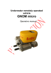
UNDERWATER REMOTELY OPERATED
VEHICLE FOR INSPECTIONS
(microROV “GNOM”)
2008
-1-
Warning!!!
Voltage on a cable is 180VDC!
Do not tuch the cable in a water during operation!
If any damages happened on a shield of cable it must
be repaired or changed !
Attention! AC power maximum 240V!
Table of contents
1. Description.
1.1
Purpose...............................................................3
1.2
Main features.......................................................3
1.3
Design…..…..........................................................4
1.4
Specifications.......................................................6
2. User's manual for operation..........................................7
3. Engineer's mode..........................................................13
4. Appendix
-2-
1. Description
1.1 What is GNOM.
Remotely operated underwater vehicle GNOM is intended for inspection of underwater wrecks
and other objects by videocamera.
The modern computer and telecommunication technologies are used in the device, and made it
easy in handling, compact, light and inexpensive.
These solutions allowed to use thin (only 3 mm diameter) and flexible communication cable for
transmission data, power and video signals to/from vehicle. The special Kevlar threads have
been used to improve the cable's tensile strength. Because of this fact, the device keeps the
highest degree of stabilization what is very important for inspections. The vehicle has a good
maneuverability and can easily turn on the spot.
High-effective electric motors with magnetic couplings and hi-tech electronics are used in the
vehicle, provide the fast speed of the GNOM with low power consumption.
One of the most important features of this device is a possibility to operate it from PC and via
Lan/Internet.
The GNOM, in essence, an underwater helicopter with the video-camera which moves in any
direction according to the operator's instructions.
1.2
Main features:
•
•
•
•
•
•
•
•
•
•
•
•
•
Color High Resolution video-camera with tilt servo and digital zoom
4 thrusters, adjustable speed
Slow/fast mode, tilting vehicle mode
LEDs lights
Flexible thin cable
Device is fitted out with the depth gauge, autodepth mode
Heading (compass), autoheading
Videotext overlays with graphics
On screen menus
Easy game joystick control
Digital data channel
PC interface, Lan/Internet web video/control
All packed in 2 cases, hand carried
-3-
3. Operation.
Put the vehicle into the water. To start operation press key MODE (for Logitech Cordless
Action™ Controller) or “X” and MODE (for Logitech Cordless Precision™ Controller) on a
joystick.
All control functions are described on a console draw (see below).
To move vehicle Forward/Back and turn Left/Right use right joystick.
To move vehicle Up/Down use left joystick.
For Tilt vehicle up/down click left joystick and hold it then move.
Arrows on a screen overlay show direction of vehicle and speed in %.
To switch and adjust lights use pads R1/R2. For version with grabber press and hold X and
use R1/R2.
To fix vehicle on a depth you need use Autodepth key, you can change depth from left joystick,
autodepth holds vehicle on a current depth.
Jump mode allows to push vehicle slightly for distance 10-30cm then stop. Select this mode by
key O on a joystick. Message Jump mode is indicated on an overlay. To jump forward/back use
arrows Up/Down. Also to turn vehicle slightly use Left/Right arrows.
Slow mode (50% power) is good for surveys with no currents. To enter it click right joystick.
"POWER 50%" is indicated on a overlay. To exit press it again. You can see "POWER 100%"
is indicated.
Jump/Tilt mode (pad O, word “tilt” is indicated on a screen ).
For tilting cam up/down use L1/L2 pads.
You can make picture larger by Zoom function. It is a digital Zoom means digital processing of
the image to do it larger (3 times max).
To select Tilt/Jump mode press key O on a joystick. See overlay word "Tilt". Then press L1
and arrow Up/Down together to make object larger/smaller.
Compass. You can see on an overlay direction of movement (rectangular) and azimuth
indication in grad. Compass shows correct value when vehicle runs. If vehicle stops value can be
not correct because of influence of magnets of motors and couplings.
Autoheading controls from the «Start» key.
Depth gauge. Indication of depth is on an overlay (down) in meters. Accuracy of gauge is less
than 10% in a shallow depth (0-5m) and becomes better till 0.5% in a max depth. Use
calibration procedure to correct it.
Voltage. In a right down corner of overlay the batery voltage is indicated. Normally system
works correctly if voltage more 11V, then you hear Beep signal of low charge. But you can
continue operation you should decrease power of thrusters and continue operation further.
-4-
2.2. Keys and buttons at the control panel
Jump Mode – jump
movement,
Tilt Mode – camera zoom/pan
Cam up/down - L1/L2
Cam center - L1+L2
Grabber grips - R1/R2
lights ON/OFF - (X+R1+R2)
adjust lights - X+R1 or X+R2
Screen overerlays
Autodepth on/off
Select cams/
lasers on/off
Switch Tilt/Jump
Fix vertical
speed
Autoheading
on/off
Up/Down
Click and hold – tilt ROV
Forward/Back
Turn Left/Right
Click - Slow speed
-5-
2.3. Overlays
N
!
Light: 100%
Jump Forward/Back: 5
Jump Right/Left: 5
150 °
W
E
direction
and value
of heading
Current camera. Disappears.
S
Autohead 150
Value of
jump/thrusters'
maximum speed.
Disappears.
Main camera
Auto stable depth
50
72
Autohead on
51
Direction and speed
of the thrusters'
rotation. Disappears
with the thrusters'
stop.
Autodepth: 10.0 m
Depth: 10.4 m
12.1В
Battery
voltage
Mode 1
N
Jump Forward/Back: 5
Jump Right/Left: 5
W
150°
S
Depth: 10.4 m
Mode 2
-6-
E
Mode 3 is only the video-image with no overlay.
2.4. Calibration.
To enter this mode you should be in start mode (message WELCOME is indicated). To calibrate
depth sensor and compass you should press key X and hold it for 7-8 sec only while message
WELCOME is indicated. Message "Calibration mode" appears. To select function you should
use left arrows.
-
To calibrate depth sensor you should set 0m when GNOM is on a surface. To finish
calibration press Enter (right key O). We recommend to set depth 0 in 5 minutes after
power ON.
To return from calibration menu set the cursor to word Exit and press Enter.
8. Finishing of operation.
To finish operation switch power OFF then disconnect cables and pull it into the reel.
Please avoid nods and twisting of cable.
WARNINGS!!!
clean propellers and shafts of motors and wash the
vehicle in a fresh water.
Use silicon oil spray for lubrication shafts of props every time after
diving. Oil must penetrate inside of conus heads of motors.
After operation please
-7-
2.5. Operation with 2 cameras.
If you have standard version with 4 thrusters and want to use 2 cameras you should remove
rear thruster, install 2nd camera (connectors described below) and change floatation.
For this you should do the following:
- remove floatation (one screw above ),
- look at draw with connectors,
- unscrew rear thruster from back roof,
- unplug it’s cable from socket,
- unplug additional empty socket,
- camera has cables marked S and V,
plug it according the draw,
- set the camera up or down and screw it,
- take new floatation and screw it the same like the old one.
- enter Engineer mode,
- select "Cameras" and set 2,
- select "Tale thruster" and set N/A.
- exit Engineer mode.
- to switch cameras from joystick use key "Select".
2.6. Lights.
GNOM has ultrabright adjustable LEDs lights: 14 LEDs on a front of each thruster. You can
control it by keys R1/R2. To switch lights ON full power (100%) – press R1 and R2 together.
To adjust use keys R1/R2. Power of lights is indicated on a screen overlay.
2.7. Float.
The float of the vehicle is fixed initially as a bit positive in fresh water. You can change it. To
make it more neutral or negative you should open plastic pipes (feet) and fit metal pieces
inside.
-8-
2.8. Engineer mode
Press simultaneously and hold 5 sec.
To enter this mode hold the X, L1, L2, R1, R2 together for 5 sec while WELCOME is displayed
on screen, then you will see words “Engineer mode”.
In this mode Up/Down arrows (located on the left) move cursor, and the "O" key operates like
Enter key on PC. To change the direction of the thruster you should move cursor to "Front
drive", "Tail drive", "Left drive", "Right drive" to select direction. Press "O" key to fix a change.
Note: "Tail drive" has three values: "Normal", "Reverse" and special "N/A" – for devices without
rear motor. Be sure do not set "N/A" mode if you have rear motor.
To change configuration of system (if you add or remove some parts) you should do the
following:
For lasers or additional lights set 1 cam+lasers.
For 2 cameras set 2 cam.
For 1 cam set 1 cam.
Some new external devices (sonar, grabber, sensors, etc.) can be added in future and included
to this menu.
For operations with new horizontal powerful thrusters is necessary to set
max power 80%. In this mode power is limited only if operator switch all 4 thrusters
together more than 80% of power.
For this you should set “safe mode truth” in this menu.
To return press pad "O".
-9-