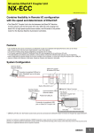
1
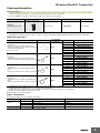
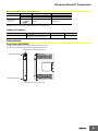
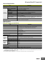
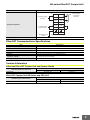
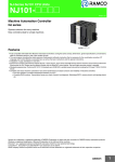
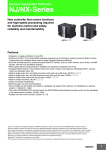
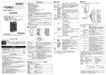
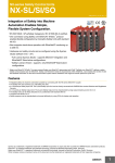
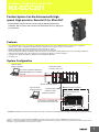
NX-series EtherCAT Coupler Unit
NX-ECC201
CSM_NX-series EtherCAT Coupler Unit_DS_EA
Flexible System Can Be Achieved with Highspeed, High-precision Remote I/O for EtherCAT
• The EtherCAT Interface Unit to connect with the Machine Automation
Controller. NX-I/O series with screwless terminal blocks for easy wiring can
be connected.
Features
• Up to 63 NX-IO Units can be connected to one EtherCAT Coupler Unit. This offers flexible and space-saving system configuration.*1
• A single slave enables configuration with different types of I/O Units, which can save nodes to be connected.
• I/O control and safety control can be integrated by connecting Units for safety.*2
• Distributed Clock (DC) that achieves high synchronisation accuracy is supported.
• Smooth start-up just by setting node addresses with rotary switch or with tool software. Setting method can be chosen according to application.
• Setting can be made with only a slave by directly connecting Sysmac Studio to the built-in USB port.
*1 Input per slave: Maximum 1024 bytes, Output per slave: Maximum 1024 bytes
*2 Available soon
System Configuration
Sysmac Studio
Support Software
EtherCAT master*
NJ-series CPU Unit
Connection to peripheral USB port or
built-in EtherNet/IP port on NJ-series
CPU Unit
Built-in EtherCAT port
Sysmac Studio
Support Software
●EtherCAT Slave Terminal
Communications cable
Ethernet cables
Peripheral USB port.
NX Series
EtherCAT Coupler Unit
NX-ECC201
Connection to peripheral USB
port on EtherCAT Coupler Unit
NX Units
End Cover
* OMRON CJ1W-NC@81/@82 Position Control Units cannot be connected to the EtherCAT Slave Terminal even though they support EtherCAT.
Sysmac® is a trademark or registered trademark of OMRON Corporation in Japan and other countries for OMRON factory automation products.
EtherCAT® is a registered trademark of Beckhoff Automation GmbH for their patented technology. Other company names and product names in this document are the
trademarks or registered trademarks of their respective companies.
1
NX-series EtherCAT Coupler Unit
Ordering Information
International Standards
• The standards are abbreviated as follows: U: UL, U1: UL(Class I Division 2 Products for Hazardous Locations), C: CSA, UC: cULus, UC1: cULus (Class I Division
2 Products for Hazardous Locations), CU: cUL, N: NK, L: Lloyd, CE: EC Directives, and KC: KC Registration.
• Contact your OMRON representative for further details and applicable conditions for these standards.
Unit type
Product Name
Current consumption
Model
Standards
EtherCAT Coupler Unit
NX Series
EtherCAT Coupler Unit
1.45 W or lower
NX-ECC201
UC1, CE, KC
Recommended EtherCAT Communications Cables
Use Straight STP (shielded twisted-pair) cable of category 5 or higher with double shielding (braiding and aluminum foil tape) for EtherCAT.
Cabel with Connectors
Item
Recommended
manufacturer
Appearance
Standard type
Cable with Connectors on Both Ends (RJ45/RJ45)
Wire Gauge and Number of Pairs: AWG27, 4-pair Cable
Cable Sheath material: LSZH *2
Cable color: Yellow *3
OMRON
Rugged type
Cable with Connectors on Both Ends (RJ45/RJ45)
Wire Gauge and Number of Pairs: AWG22, 2-pair Cable
OMRON
Rugged type
Cable with Connectors on Both Ends (M12 Straight/
RJ45)
Wire Gauge and Number of Pairs: AWG22, 2-pair Cable
OMRON
Rugged type
Cable with Connectors on Both Ends (M12 Right-angle/
RJ45)
Wire Gauge and Number of Pairs: AWG22, 2-pair Cable
OMRON
Cable length(m) *1
Model
0.3
XS6W-6LSZH8SS30CM-Y
0.5
XS6W-6LSZH8SS50CM-Y
1
XS6W-6LSZH8SS100CM-Y
2
XS6W-6LSZH8SS200CM-Y
3
XS6W-6LSZH8SS300CM-Y
5
XS6W-6LSZH8SS500CM-Y
0.3
XS5W-T421-AMD-K
0.5
XS5W-T421-BMD-K
1
XS5W-T421-CMD-K
2
XS5W-T421-DMD-K
5
XS5W-T421-GMD-K
10
XS5W-T421-JMD-K
0.3
XS5W-T421-AMC-K
0.5
XS5W-T421-BMC-K
1
XS5W-T421-CMC-K
2
XS5W-T421-DMC-K
5
XS5W-T421-GMC-K
10
XS5W-T421-JMC-K
0.3
XS5W-T422-AMC-K
0.5
XS5W-T422-BMC-K
1
XS5W-T422-CMC-K
2
XS5W-T422-DMC-K
5
XS5W-T422-GMC-K
10
XS5W-T422-JMC-K
*1 Standard type cables length 0.2, 0.3, 0.5, 1, 1.5, 2, 3, 5, 7.5, 10, 15 and 20m are available.
Rugged type cables length 0.3, 0.5, 1, 2, 3, 5, 10 and 15m are available.
*2 The lineup features Low Smoke Zero Halogen cables for in-cabinet use and PUR cables for out-of-cabinet use.
*3 Cables colors are available in blue, yellow, or Green
Note: For details, refer to Cat.No.G019.
Cables / Connectors
Wire Gauge and Number of Pairs: AWG24, 4-pair Cable
Item
Cables
RJ45 Connectors
Appearance
Recommended manufacturer
Model
-
Hitachi Cable, Ltd.
NETSTAR-C5E SAB 0.5 × 4P*
-
Kuramo Electric Co.
KETH-SB*
-
SWCC Showa Cable Systems Co.
FAE-5004*
-
Panduit Corporation
MPS588-C*
* We recommend you to use above cable and connector together.
2
NX-series EtherCAT Coupler Unit
Wire Gauge and Number of Pairs: AWG22, 2-pair Cable
Item
Appearance
Cables
Recommended manufacturer
Model
-
Kuramo Electric Co.
KETH-PSB-OMR*
-
Nihon Electric Wire&Cable Co.,Ltd.
PNET/B*
OMRON
XS6G-T421-1*
RJ45 Assembly
Connector
* We recommend you to use above cable and connector together.
Note: Connect both ends of cable shielded wires to the connector hoods.
Optional Products
Product name
Cording Pins
Specification
Pins for 10 Units
(30 terminal block pins and 30 Unit pins)
Model number
Standards
NX-AUX02
Accessories
End Cover (NX-END01)
An End Cover is connected to the end of the EtherCAT Slave Terminal.
One End Cover is provided together with the EtherCAT Coupler Unit.
Protrusions for removing the Unit
Unit hookup guide
Unit hookup guide
Protrusions for removing the Unit
3
NX-series EtherCAT Coupler Unit
General Specification
Item
Enclosure
Specification
Mounted in a panel
Ground to 100 Ω or less
Grounding method
Ambient operating temperature 0 to 55°C
Operating
environment
Ambient operating humidity
10% to 95% (with no condensation or icing)
Atmosphere
Must be free from corrosive gases.
Ambient storage temperature
−25 to 70°C (with no condensation or icing)
Altitude
2,000 m max.
Pollution degree
Pollution degree 2 or less: Conforms to JIS B3502 and IEC 61131-2.
Noise immunity
Conforms to IEC61000-4-4. 2 kV (power supply line)
Overvoltage category
Category II: Conforms to JIS B3502 and IEC 61131-2.
EMC immunity level
Zone B
Vibration resistance
Conforms to IEC 60068-2-6.
5 to 8.4 Hz with 3.5-mm amplitude, 8.4 to 150 Hz, acceleration of 9.8 m/s2, 100 min each in
X, Y, and Z directions (10 sweeps of 10 min each = 100 min total)
Shock resistance
Conforms to IEC 60068-2-27. 147 m/s2, 3 times each in X, Y, and Z directions
cULus: Listed UL508 and ANSI/ISA 12.12.01
EC: EN 61131-2 and C-Tick, KC Registration
Applicable standards
Specifications
EtherCAT Coupler Unit NX-ECC201
Item
Specification
Model
NX-ECC201
No. of connectable NX Units
63 Units max.
Send/receive PDO data sizes
Input: 1,024 bytes max. (including input data, status, and unused areas)
Output: 1,024 bytes max. (including output data and unused areas)
Mailbox data size
Input: 256 bytes
Output: 256 bytes
Mailbox
Emergency messages, SDO requests, and SDO information
Refreshing methods
Free-run refreshing
I/O-synchronized refreshing
Node address setting range
1 to 192 *1
I/O jitter performance
Inputs: 1 µs max.
Outputs: 1 µs max.
Communications cycle
250 to 100,000 µs*2*3
Unit power
supply
Power supply voltage
24 VDC (20.4 to 28.8 VDC)*4
NX Unit power supply capacity
10 W max.
Refer to Installation orientation and restrictions for details.
NX Unit power supply efficiency
70%
Isolation method
No isolation between NX Unit power supply and Unit power supply terminals
Unwired terminal current capacity 4 A max.
I/O power
supply
Power supply voltage
5 to 24 VDC (4.5 to 28.8 VDC)
Maximum I/O power supply
current
4 A max.
Power supply terminal current
capacity
4 A max.
NX Unit power consumption
1.45 W max.
Current consumption from I/O power supply
10 mA max. (for 24 VDC)
Dielectric strength
510 VAC for 1 min, leakage current: 5 mA max. (between isolated circuits)
Insulation resistance
100 VDC, 20 MΩ min. (between isolated circuits)
*1. This specification applies to a connection to the built-in EtherCAT port on an NJ-series CPU Unit.
*2. This depends on the specifications of the EtherCAT master. The values are as follows when you are connected to the builti-in EtherCAT port
on an NJ5-series CPU Unit: 500 µs, 1,000 µs, 2,000 µs, and 4,000 µs. Refer to the NJ-series CPU Unit Built-in EtherCAT Port User's Manual
(Cat. No. W505) for the most recent specifica-tions.
*3. This depends on the Unit configuration.
*4. Use an output voltage that is appropriate for the I/O circuits of the NX Units and the connected external devices.
4
NX-series EtherCAT Coupler Unit
Item
Specification
Communications Connector
For EtherCAT communications.
• RJ45 × 2 (shielded)
• IN: EtherCAT input data, OUT: EtherCAT output data
External connection terminals
Screwless Clamping Terminal Block (8 terminals)
For Unit power supply, I/O power supply, and grounding. Removable.
Peripheral USB Port
For Sysmac Studio connection.
• Physical layer: USB 2.0-compliant, B-type connector
• Transmission distance: 5 m max.
Dimensions
46 × 103 × 71 mm (W × H × D)
Weight
150 g max.
Installation orientation: 6 possible orientations
Restrictions:
• Used in the upright installation orientation.
10-W output, 40ºC
Output power [W]
12
10
8.5-W output, 55ºC
8
6
4
2
0
0
10
20
30
40 45 50 55 60
Ambient temperature [ºC]
Installation orientation and restrictions
• Used in another orientation other than the upright installation orientation.
10-W output, 40ºC
Output power [W]
12
10
8
6.0-W output, 55ºC
6
4
2
0
0
10
20
30
40 45 50 55 60
Ambient temperature [ºC]
Peripheral
USB port
IN communications
connector
OUT communications
connector
Internal
circuits
UV
UV
Circuit layout
UG
UG
Terminal
block
UNIT PWR LED
Non-isolated
power supply
circuits
NX Unit
power supply +
NX Unit
power supply -
IOV
NX bus
connector
I./O power
supply +
IOG
I/O PWR LED
I/O power
supply DIN Track contact plate
5
NX-series EtherCAT Coupler Unit
Item
Specification
A1
B1
UV
UV
UG
UG
IOV
IOG
Through-wiring
for unwired
terminals.
Unit power supply
(24 VDC)
Terminal arrangement
I./O power supply
(5 to 24 VDC)
Ground to 100Ω
or less
Accessory
A8
B8
End Cover (NX-END0): 1
EtherCAT Communications Specifications
Item
Specification
Communications standard
IEC 61158 Type 12
Physical layer
100BASE-TX (IEEE 802.3)
Modulation
Baseband
Baud rate
100 Mbps
Topology
Depends on the specifications of the EtherCAT master.
Transmission media
Category 5 or higher twisted-pair cable (Recommended cable: double-shielded cable
with aluminum tape and braiding)
Transmission distance
Distance between nodes: 100 m or less
Version Information
NX-series EtherCAT Coupler Unit and Sysmac Studio
NX-series EtherCAT Coupler Unit
NX-ECC201
Sysmac Studio
Version 1.05 or lower
Version 1.06 or higher
Not supported
Supported
EtherCAT Coupler Unit NX Series and CPU Unit
EherCAT Coupler Unit NX Series
NX-ECC201
CPU Unit
Unit version 1.04 or lower
Unit version 1.05 or higher
Not supported
Supported
6
NX-series EtherCAT Coupler Unit
External Interface
EtherCAT Coupler Unit NX-ECC201
(B)
(D)
RUN
(C)
(E)
(F)
(C)
(G)
(A)
Symbol
Name
Function
(A)
NX bus connector
This connector is used to connect each Unit.
(B)
Indicators
The indicators show the current operating status of the Unit.
(C)
Communications connectors
These connectors are connected to the communications cables of the EtherCAT network.
There are two connectors, one for the input port and one for the output port.
(D)
Peripheral USB port
This port is used to connect to the Sysmac Studio Support Software.
(E)
Terminal block
The terminal block is used to connect external devices.
The number of terminals depends on the type of Unit.
(F)
Rotary switches
These rotary switches are used to set the 1s digit and 10s digit of the node address of the
EtherCAT Coupler Unit as an EtherCAT slave. The address is set in decimal.
(G)
DIP switch
The DIP switch is used to set the 100s digit of the node address of the EtherCAT Coupler Unit
as an EtherCAT slave.
Terminal Block
(A)
(B)
A1
B1
A2
B2
A3
B3
A4
B4
A5
B5
A6
B6
A7
B7
A8
B8
(C)
Eight-terminal Block
Symbol
Name
Function
The terminal numbers (A1 to A8 and B1 to B8) are displayed.
Terminal number indications
The terminal number indicators are the same regardless of the number of terminals on the
terminal block, as shown above.
(B)
Release holes
Insert a flat-blade screwdriver into these holes to connect and remove the wires.
(C)
Terminal holes
The wires are inserted into these holes.
(A)
7
NX-series EtherCAT Coupler Unit
Applicable Wires
Using Ferrules
If you use ferrules, attach the twisted wires to them.
Observe the application instructions for your ferrules for the wire stripping length when attaching ferrules.
Always use one-pin ferrules. Do not use two-pin ferrules.
The applicable ferrules, wires, and crimping tool are given in the following table.
Terminal types
Terminals other
than ground
terminals
Manufacturer
Phoenix
Contact
Applicable wire
(mm2 (AWG))
Ferrule model
AI0,34-8
0.34 (#22)
AI0,5-8
0.5 (#20)
Phoenix Contact (The figure in parentheses is the applicable wire
size.)
CRIMPFOX 6 (0.25 to 6 mm2, AWG 24 to 10)
AI0,5-10
AI0,75-8
Crimping tool
0.75 (#18)
AI0,75-10
AI1,0-8
1.0 (#18)
AI1,0-10
AI1,5-8
1.5 (#16)
AI1,5-10
Ground
terminals
Terminals other
than ground
terminals
Weidmuller
AI2,5-10
2.0 *1
H0.14/12
0.14 (#26)
H0.25/12
0.25 (#24)
H0.34/12
0.34 (#22)
H0.5/14
0.5 (#20)
Weidmueller (The figure in parentheses is the applicable wire size.)
PZ6 Roto (0.14 to 6 mm2, AWG 26 to 10)
H0.5/16
H0.75/14
0.75 (#18)
H0.75/16
H1.0/14
1.0 (#18)
H1.0/16
H1.5/14
1.5 (#16)
H1.5/16
*1. Some AWG 14 wires exceed 2.0 mm2 and cannot be used in the screwless clamping terminal block.
When you use any ferrules other than those in the above table, crimp them to the twisted wires so that the following processed dimensions are
achieved.
8 to 10 mm
1.6 mm max.
(Terminals other than ground terminals)
2.4 mm max.
(Terminals other than ground terminals)
2.7 mm max.
(Ground terminals)
2.0 mm max.
(Ground terminals)
Using Twisted Wires/Solid Wires
If you use the twisted wires or the solid wires, the applicable wire range and conductor length (stripping length) are as follows.
Use the twisted wires to connect the ground wire to a ground of 100 Ω or less. Do not use the solid wires.
Terminal types
Applicable wire range
Conductor length (stripping length)
Ground terminals
2.0 mm2
9 to 10 mm
Terminals other than ground
terminals
0.08 to 1.5 mm2
AWG28 to 16
8 to 10 mm
Conductor length (stripping length)
8
NX-series EtherCAT Coupler Unit
Dimensions
(Unit: mm)
EtherCAT Coupler Unit NX-ECC201
● EtherCAT Coupler Unit Only
48.1
46
1.5
104.5
100
1.5
65.2
71
80
● With Cables Connected
*1
100 to 120 *2
5.8
71
USB cable
Communications cable
*1. This dimension depends on the specifications of the commercially available USB cable. Check the specifications of the USB cable that is used.
*2. This is the dimension from the back of the Unit to the communications cables.
• 100 mm: When an MPS588-C Connector is used.
• 120 mm: When an XS6G-T421-1 Connector is used.
9
NX-series EtherCAT Coupler Unit
● End Cover
12
1.5
100
1.5
71
Related Manuals
Man.No
W519
Model
NX-ECC201
Manual
Application
Description
NX-series EtherCAT
Coupler Unit User’s Manual
Leaning how to use an
NX-series EtherCAT
Coupler Unit and
Ether-CAT Slave Terminals
The following items are described: the overall
system and configuration methods of an EtherCAT
Slave Terminal (which consists of an NX-series
EtherCAT Coupler Unit and NX Units), and
information on hardware, setup, and functions to set
up, control, and monitor NX Units through EtherCAT.
10