1
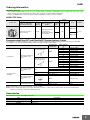
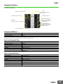
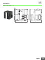
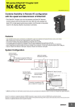
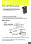
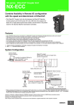
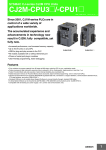
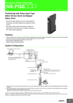
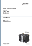
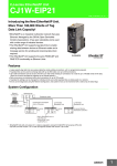
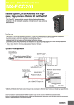
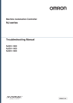
NJ-Series NJ301 CPU Units NJ301-@@@@ CSM_NJ301_DS_E_1_1 Machine Automation Controller NJ series New controller that covers functions and high-speed processing required for machine control and safety, reliability and maintainability that are the features of industrial controllers NJ301-1200 Features • Architecture Based on new Intel® Atom™ Processor • The user program including the double precision floating point arithmetic instruction that is necessary for the coordinates correction, ST language and Function Blocks is executed fast, as well as the basic instructions and the special instructions. • Integration of Logic and Motion in one CPU • Synchronous control of all machine network devices : vision sensors, servo drives and field devices with the machine control network, EtherCAT. Synchronize the PLC Engine and the Motion Engine with the EtherCAT control period. Fast and highly-accurate control is possible. • Standard programming : Conforms IEC 61131-3 standards, variable-based instructions including the PLCopen Motion function blocks • Complete and robust machine automation: fast control performance and basic functions and reliability of industrial controllers • Fan-free operation in ambient temperature between 0 to 55°C • Complete RAS functions: Transmission frame error check, timeout, bus diagnosis, Watchdog (WDT), memory check, and topology check, etc. Sysmac is a trademark or registered trademark of OMRON Corporation in Japan and other countries for OMRON factory automation products. Intel, the Intel logo, Intel Atom are trademarks of Intel Corporation in the U.S. and/or other countries. Windows is registered trademarks of Microsoft Corporation in the USA and other countries. EtherCAT® is a registered trademark of Beckhoff Automation GmbH for their patented technology. Other company names and product names in this document are the trademarks or registered trademarks of their respective companies. This product incorporates certain third party software. The license and copyright information associated with this software is available at http://www.fa.omron.co.jp/nj_info_e/. 1 NJ301 Ordering Information International Standards • The standards are abbreviated as follows: U: UL, U1: UL(Class I Division 2 Products for Hazardous Locations), C: CSA, UC: cULus, UC1: cULus (Class I Division 2 Products for Hazardous Locations), CU: cUL, N: NK, L: Lloyd, and CE: EC Directives. • Contact your OMRON representative for further details and applicable conditions for these standards. NJ301 CPU Units Current consumption (A) Specifications Product Name I/O capacity / maximum number of configuration Units (Expansion Racks) Program capacity Memory capacity for variables 5 MB 0.5 MB: Retained during power interruption 2 MB: Not retained during power interruption Number of motion axes Model 5 VDC Standards 24 VDC NJ301 CPU Units 8 2,560 points / 40 Units (3 Expansion Racks) NJ301-1200 UC1, N, L, CE − 1.90 4 NJ301-1100 Recommended EtherCAT and EtherNet/IP Communications Cables Use Straight STP (shielded twisted-pair) cable of category 5 or higher with double shielding (braiding and aluminum foil tape) for EtherCAT. Use Straight or cross STP (shielded twisted-pair) cable of category 5 or higher for EtherNet/IP. Recommended manufacturer Item Cable length (m) *1 Cable with Connectors on Both Ends (RJ45/RJ45) OMRON Wire Gauge and Number of Pairs: AWG22, 2-pair Cable For EtherCAT Cable with Connectors on Both Ends (M12/RJ45) OMRON Wire Gauge and Number of Pairs: AWG24, 4-pair Cable For EtherCAT and EtherNet/IP Wire Gauge and Number of Pairs: AWG22, 2-pair Cable Cables 0.3 XS5W-T421-AMD-K 0.5 XS5W-T421-BMD-K 1 XS5W-T421-CMD-K 2 XS5W-T421-DMD-K 5 XS5W-T421-GMD-K 10 XS5W-T421-JMD-K 0.3 XS5W-T421-AMC-K 0.5 XS5W-T421-BMC-K 1 XS5W-T421-CMC-K 2 XS5W-T421-DMC-K 5 XS5W-T421-GMC-K 10 XS5W-T421-JMC-K Tonichi Kyosan Cable, Ltd. NETSTAR-C5E SAB 0.5 × 4P Kuramo Electric Co. KETH-SB SWCC Showa Cable Systems Co. FAE-5004 RJ45 Connectors Panduit Corporation MPS588 Cables Kuramo Electric Co. KETH-PSB-OMR *2 OMRON XS6G-T421-1 *2 RJ45 Assembly Connector Wire Gauge and Number of Cables Pairs: 0.5 mm, 4-pair Cable RJ45 Connectors For EtherNet/IP Model Fujikura Ltd. F-LINK-E 0.5mm × 4P Panduit Corporation MPS588 *1. The cable length 0.3, 0.5, 1, 2, 3, 5, 10 and 15 m are available. For details, refer to Cat.No.G019. *2. We recommend you to use above cable and connector together. Note: Please be careful while cable processing, for EtherCAT, connectors on both ends should be shield connected and for EtherNet/IP, connectors on only one end should be shield connected. Accessories The following accessories come with the CPU Unit. Item Battery Specification CJ1W-BAT01 End Cover CJ1W-TER01 (necessary to be connected to the right end of the CPU Rack.) End Plate PFP-M (2 pcs) 2 NJ301 General Specification NJ301-@@@@ Item Enclosure Mounted in a panel Grounding Method Ground to less than 100 Ω Dimensions (height×depth×width) 90 mm × 90 mm × 90 mm Weight 550 g (including the End Cover) Current Consumption 0 to 55°C Ambient Operating Humidity 10% to 90% (with no condensation) Atmosphere Must be free from corrosive gases. Ambient Storage Temperature -20 to 75°C (excluding battery) Altitude Operation Environment Pollution Degree Battery 5 VDC, 1.90 A (including SD Memory Card and End Cover) Ambient Operating Temperature 2,000 m or less 2 or less: Conforms to JIS B3502 and IEC 61131-2. Noise Immunity 2 kV on power supply line (Conforms to IEC 61000-4-4.) Overvoltage Category Category II: Conforms to JIS B3502 and IEC 61131-2. EMC Immunity Level Zone B Vibration Resistance Conforms to IEC 60068-2-6. 5 to 8.4 Hz with 3.5-mm amplitude, 8.4 to 150 Hz Acceleration of 9.8 m/s2 for 100 min in X, Y, and Z directions (10 sweeps of 10 min each = 100 min total) Shock Resistance Conforms to IEC 60068-2-27. 147 m/s2, 3 times in X, Y, and Z directions (100 m/s2 for Relay Output Units) Life 5 years at 25°C Model Applicable Standards CJ1W-BAT01 Conforms to cULus, NK, LR and EC Directives. 3 NJ301 Performance Specifications NJ301- Item Processing Time Instruction Execution Times 1200 Ladder Diagram Instructions (LD, AND, OR, and OUT) 3.0 ns or more Math Instructions (for Long Real Data) 42 ns or more Program capacity *1 Programming 5 MB Memory Capacity for Variables Retain Attribute *2 0.5 MB No Retain Attribute *3 2 MB Memory for CJ-Series Units (Can be Specified with AT Specifications for Variables.) CIO Area 6,144 words (CIO 0 to CIO 6143) Maximum Number of Connectable Units Work Area 512 words (W0 to W511) Holding Area 1,536 words (H0 to H1535) DM Area 32,768 words (D0 to D32767) EM Area 32,768 words × 4 banks (E0_00000 to E3_32767) Maximum per CPU Rack or Expansion Rack 10 Units Entire Controller 40 Units Maximum number of Expansion Racks Unit Configuration I/O Capacity Power Supply Unit for CPU Rack and Expansion Racks Number of Controlled Axes 2,560 points max. Model NJ-P@3001 AC Power Supply 30 to 45 ms Power OFF Detection Time DC Power Supply 22 to 25 ms Maximum Number of Controlled Axes 8 axes 4 axes Maximum Number of Axes for Single-axis Control 8 axes max. 4 axes max. Maximum Number of Axes for 4 axes per axes group Linear Interpolation Axis Control 2 axes per axes group Maximum Number of Axes Groups 32 groups Motion Control Period The same control period as that is used for the process data communications cycle for EtherCAT. Cams Number of Cam Data Points Maximum Points per Cam Table 65,535 points Maximum Points 262,140 points for All Cam Tables Maximum Number of Cam Tables 160 tables Position Units Pulses, millimeters, micrometers, nanometers, degrees or inches Override Factors 0.00% or 0.01% to 500.00% Supported Services Sysmac Studio connection Peripheral USB Physical Layer Port Transmission Distance between Hub and Node Built-in EtherNet/IP Port 3 max. Maximum number of I/O Points on CJ-series Units Number of Axes for Circular Interpolation Axis Control Motion Control 1100 USB 2.0-compliant B-type connector 5 m max. Physical Layer 10Base-T or 100Base-TX Media Access Method CSMA/CD Modulation Baseband Topology Star Baud Rate 100 Mbps (100Base-TX) Transmission Media STP (shielded, twisted-pair) cable of Ethernet category 5, 5e or higher Maximum Transmission Distance between Ethernet Switch and Node 100m Maximum Number of Cascade Connections There are no restrictions if Ethernet switch is used. *1. This is the capacity for the execution objects and variable tables (including variable names). *2. Words for CJ-series Units in the Holding, DM, and EM Areas are not included. *3. Words for CJ-series Units in the CIO and Work Areas are not included. 4 NJ301 NJ301- Item 1200 32 Packet interval *4 10 to 10,000 ms in 1.0-ms increments Can be set for each connection. (Data will be refreshed at the set interval, regardless of the number of nodes.) Permissible Communications Band 1,000 pps *5 (including heartbeat) Maximum Number of Tag Sets 32 Tag types CIP service: Tag Data Links (Cyclic Number of tags per connection Communications) (i.e., per tag set) Built-in EtherNet/IP Port 1100 Maximum Number of Connections Network variables, CIO, Work, Holding, DM, and EM Areas 8 (7 tags if Controller status is included in the tag set.) Maximum Link Data Size per Node (total size for all tags) 19,200 bytes Maximum Data Size per Connection 600 bytes Maximum Number of Registrable Tag Sets 32 (1 connection = 1 tag set) Maximum Tag Set Size 600 bytes (Two bytes are used if Controller status is included in the tag set.) Multi-cast Packet Filter *6 Supported. Class 3 (number of connections) 32 (clients plus server) Cip Message Service: Explicit Messages Built-in EtherCAT Port UCMM (nonconnection type) Maximum Number of Clients that Can Communicate at One Time 32 Maximum Number of Servers that Can Communicate at One Time 32 Communications Standard IEC 61158 Type12 EtherCAT Master Specifications Class B (Feature Pack Motion Control compliant) Physical Layer 100BASE-TX Modulation Baseband Baud Rate 100 Mbps (100Base-TX) Duplex mode Auto Topology Line, daisy chain, and branching Transmission Media Twisted-pair cable of category 5 or higher (double-shielded straight cable with aluminum tape and braiding) Maximum Transmission Distance between Nodes 100m Maximum Number of Slaves 192 Maximum Process Data Size Inputs: 5,736 bytes Outputs: 5,736 bytes (However, the maximum number of process data frames is 4.) Maximum Process Data Size per Slave Inputs: 1,434 bytes Outputs: 1,434 bytes Maximum Communications Cycle 1,000/2,000/4,000 μs Sync Jitter Internal Clock 1 μs max. At ambient temperature of 55°C: -3.5 to +0.5 min error per month At ambient temperature of 25°C: -1.5 to +1.5 min error per month At ambient temperature of 0°C: -3 to +1 min error per month *4. Data is updated on the line in the specified interval regardless of the number of nodes. *5. Means packets per second, i.e., the number of communications packets that can be sent or received in one second. *6. An IGMP client is mounted for the EtherNet/IP port. If an ethernet switch that supports IGMP snooping is used, filtering of unnecessary multicast packets is performed. 5 NJ301 Function Specifications Item NJ301-@@@@ I/O refreshing and the user program are executed in units that are called tasks. Tasks are used to specify execution conditions and execution priority. Function Periodically Executed Tasks Tasks Maximum Number of Primary Periodic Tasks 1 Maximum Number of Periodic Tasks 3 System Service Monitoring Settings The execution interval and the percentage of the total user program execution time are monitored for the system services (processes that are executed by the CPU Unit separate from task execution). Programs POUs that are assigned to tasks. Function Blocks POUs that are used to create objects with specific conditions. Functions POUs that are used to create an object that determine unique outputs for the inputs, such as for data processing. Programming Languages Types Ladder diagrams *1 and structured text (ST) Variables External Access of Variables Setup POU (program organization units) Basic Data Types Derivative Data Types Data Types Programming Structures Unions Enumerations Data Type Attributes Array Specifications Network Variables The function which allows access from the HMI, host computers, or other Controllers. Boolean BOOL Bit Strings BYTE, WORD, DWORD, LWORD Integers INT, SINT, DINT,LINT, UINT, USINT, UDINT, ULINT Real Numbers REAL, LREAL Durations TIME Dates DATE Times of Day TIME_OF_DAY Date and Time DATE_AND_TIME Text Strings STRING Direct Derivative Types Structures, unions, enumerations Member Data Types Basic data types, structures, unions, enumerations, array variables Function A derivative data type that groups together data with different variable types. Maximum Number of Members 2048 Nesting Maximum Levels 8 Member Data Types Basic data types, structures, enumerations, unions, or array variables. Specifying Member Offsets You can use member offsets to place structure members at any memory locations. Function A derivative data type that groups together data with different variable types. Maximum Number of Members 4 Member Data Types BOOL, BYTE, WORD, DWORD, LWORD Function A derivative data type that uses text strings called enumerators to express variable values. Function An array is a group of elements with the same data type. You specify the number (subscript) of the element from the first element to specify the element. Maximum Number of Dimensions 3 Maximum Number of Elements 65535 Array Specifications for FB Instances Supported. Range Specifications You can specify a range for a data type in advance. The data type can take only values that are in the specified range. *1. Inline ST is supported. (Inline ST is ST that is written as an element in a ladder diagram.) 6 NJ301 Item NJ301-@@@@ Control Modes position control, velocity control, torque control Axis Types Servo axes, virtual servo axes, encoder axes, and virtual encoder axes Positions that can be managed Single-axis Position Control Single-axis Velocity Control Command positions and actual positions Absolute Positioning Positioning is performed for a target position that is specified with an absolute value. Relative Positioning Positioning is performed for a specified travel distance from the command current position. Interrupt Feeding Positioning is performed for a specified travel distance from the position where an interrupt input was received from an external input. Velocity Control Velocity control is performed in Position Control Mode. Cyclic Synchronous Velocity Control A velocity command is output each control period in Velocity Control Mode. Single-axis Torque Control The torque of the motor is controlled. Torque Control Single-axis Synchronized Control Motion Control Single-axis Single-axis Manual Operation Auxiliary Functions for Single-axis Control Starting Cam Operation A cam motion is performed using the specified cam table. Ending Cam Operation The cam motion for the axis that is specified with the input parameter is ended. Starting Gear Operation A gear motion with the specified gear ratio is performed between a master axis and slave axis. Positioning A gear motion with the specified gear ratio and sync position is performed between a Gear Operation master axis and slave axis. Ending Gear Operation The specified gear motion or positioning gear motion is ended. Synchronous Positioning Positioning is performed in sync with a specified master axis. Master Axis Phase Shift The phase of a master axis in synchronized control is shifted. Combining Axes The command positions of two axes are added or subtracted and the result is output as the command position. Powering the Servo The Servo in the Servo Drive is turned ON to enable axis motion. Jogging An axis is jogged at a specified target velocity. Resetting Axis Errors Axes errors are cleared. Homing A motor is operated and the limit signals, home proximity signal, and home signal are used to define home. High-speed Homing Positioning is performed for an absolute target position of 0 to return to home. Stopping An axis is decelerated to a stop. Immediately Stopping An axis is stopped immediately. Setting Override Factors The target velocity of an axis can be changed. Changing the Current Position The command current position or actual current position of an axis can be changed to any position. Enabling External Latches The position of an axis is recorded when a trigger occurs. Disabling External Latches The current latch is disabled. Zone Monitoring You can monitor the command position or actual position of an axis to see when it is within a specified range (zone). Monitoring Axis Following Error You can monitor whether the difference between the command positions or actual positions of two specified axes exceeds a threshold value. Resetting the Following Error The error between the command current position and actual current position is set to 0. Torque Limit The torque control function of the Servo Drive can be enabled or disabled and the torque limits can be set to control the output torque. 7 NJ301 Item Multi-axes Coordinated Control Axes Groups Auxiliary Functions for Multi-axes Coordinated Control Motion Control Cams Common Items Parameters NJ301-@@@@ Absolute Linear Interpolation Linear interpolation is performed to a specified absolute position. Relative Linear Interpolation Linear interpolation is performed to a specified relative position. Circular 2D Interpolation Circular interpolation is performed for two axes. Axes Group Cyclic Synchronous Absolute Positioning A positioning command is output each control period in Position Control Mode. Resetting Axes Group Errors Axes group errors and axis errors are cleared. Enabling Axes Groups Motion of an axes group is enabled. Disabling Axes Groups Motion of an axes group is disabled. Stopping Axes Groups All axes in interpolated motion are decelerated to a stop. Immediately Stopping Axes Groups All axes in interpolated motion are stopped immediately. Setting Axes Group Override Factors The blended target velocity is changed during interpolated motion. Reading Axes Group Positions The command current positions and actual current positions of an axes group can be read. Changing the Axes in an Axes Group The Composition Axes parameter in the axes group parameters can be overwritten temporarily. Setting Cam Table Properties The end point index of the cam table that is specified in the input parameter is changed. Saving Cam Tables The cam table that is specified with the input parameter is saved in non-volatile memory in the CPU Unit. Writing MC Settings Some of the axis parameters or axes group parameters are overwritten temporarily. Count Modes You can select either Linear Mode (finite length) or Rotary Mode (infinite length). Unit Conversions Acceleration/ Deceleration Control Auxiliary Functions You can set the display unit for each axis according to the machine. Automatic Acceleration/ Deceleration Control Jerk is set for the acceleration/deceleration curve for an axis motion or axes group motion. Changing the Acceleration and Deceleration Rates You can change the acceleration or deceleration rate even during acceleration or deceleration. In-position Check You can set an in-position range and in-position check time to confirm when positioning is completed. Stop Method You can set the stop method to the immediate stop input signal or limit input signal. Re-execution of Motion Control Instructions You can change the input variables for a motion control instruction during execution and execute the instruction again to change the target values during operation. Multi-execution of Motion Control Instructions (Buffer Mode) You can specify when to start execution and how to connect the velocities between operations when another motion control instruction is executed during operation. Continuous Axes Group Motions (Transition Mode) You can specify the Transition Mode for multi-execution of instructions for axes group operation. 8 NJ301 Item Auxiliary Functions Monitoring Functions Motion Control NJ301-@@@@ Software Limits The movement range of an axis is monitored. Following Error The error between the command current value and the actual current value is monitored for an axis. Velocity, Acceleration Rate, Deceleration Rate, Torque, Interpolation Velocity, Interpolation Acceleration Rate, And Interpolation Deceleration Rate You can set warning values for each axis and each axes group to monitor them. Absolute Encoder Support The Servo Drive input signals listed on the right are used. Home signal, home proximity signal, positive limit signal, negative limit signal, immediate stop signal, and interrupt input signal External Interface Signals Maximum Number of Slaves EtherCAT Slaves Basic I/O Units CJ-Series Units 192 Chattering and Noise Input response times are set. Countermeasures Maximum number of Units Unit (I/O) Management You can use an OMRON G5-Series Servomotor with an Absolute Encoder to eliminate the need to perform homing at startup. 40 Chattering and Noise Input response times are set. Countermeasures Basic I/O Units Load Short-circuit Protection and I/O Alarm information for Basic I/O Units is read. Disconnection Detection A port for communications with various kinds of Support Software running on a personal computer. Peripheral USB Port Communications protocol TCP/IP, UDP/IP Programless cyclic data exchange is performed with the devices on the EtherNet/IP Tag Data Links CIP network. Communications Message Service CIP commands are sent to or received from the devices on the EtherNet/IP network. Communications EtherNet/IP Port TCP/IP Applications Communications Supported Services EtherCAT Port Operation Management Socket Services Data is sent to and received from any node on Ethernet using the UDP or TCP protocol. Socket communications instructions are used. FTP Server Files can be read from or written to the SD Memory Card in the CPU Unit from computers at other Ethernet nodes. Automatic Clock Adjustment Clock information is read from the NTP server at the specified time or at a specified interval after the power supply to the CPU Unit is turned ON. The internal clock time in the CPU Unit is updated with the read time. SNMP Agent Built-in EtherNet/IP port internal status information is provided to network management software that uses an SNMP manager. Process Data Control information is exchanged in cyclic communications between the EtherCAT master Communications and slaves. Control information is exchanged in noncyclic event communications between the SDO EtherCAT master and slaves. SDO communications that are defined in the CANopen Communications standard are used. Network Scanning Information is read from connected slave devices and the slave configuration is automatically generated. DC (Distributed Clock) Time is synchronized by sharing the EtherCAT system time among all EtherCAT devices (including the master). Enable/disable Settings for Slaves The slaves can be enabled or disabled as communications targets. Disconnecting/Connecting Slaves Temporarily disconnects a slave from the EtherCAT network for maintenance, such as for replacement of the slave, and then connects the slave again. Supported Application Protocol SDO messages that conform to the CANopen standard can be sent to slaves via EtherCAT. CoE Communications Instructions The following instructions are supported. CIP communications instructions, socket communications instructions, SDO message instructions, no-protocol communications instructions, and protocol macro instructions RUN Output Contacts The output on the NJ-P@3001 Power Supply Unit turns ON in RUN mode. 9 NJ301 Item System Management NJ301-@@@@ Categories Events are recorded in the following logs. System event log Access event log User-defined event log Maximum Number of Events per Event Log 512 Event Logs Programs, function blocks, functions, and global variables can be changed online. Different operators can change different POUs across a network. Online Editing Forced Refreshing Maximum Number of Forced Variables Device Variables for CJ-series Units 64 and Variables with AT Specifications Motor operation and wiring can be checked from the Sysmac Studio. Synchronizing The project file in the Sysmac Studio and the data in the CPU Unit can be made the same when online. Debugging Data Tracing Single Triggered Trace When the trigger condition is met, the specified number of samples are taken and then tracing stops automatically. Continuous Trace Data tracing is executed continuously and the trace data is collected by the Sysmac Studio. Maximum Number of Simultaneous Data Trace 2 Maximum Number of Records 10,000 Sampling Maximum Number of Sampled Variables 48 variables Timing of Sampling Sampling is performed for the specified task period, at the specified time, or when a sampling instruction is executed. Triggered Traces Trigger conditions are set to record data before and after an event. Trigger Conditions When BOOL variable changes to TRUE or FALSE Comparison of non-BOOL variable with a constant Comparison Method: Equals (=), Greater than (>), Greater than or equals (≥), Less Than (<), Less than or equals (≤), Not equal (≠) Delay Trigger position setting: A slider is used to set the percentage of sampling before and after the trigger condition is met. Simulation The operation of the CPU Unit is emulated in the Sysmac Studio. Connections to Connected Port HMIs Built-in EtherNet/IP port Sysmac Studio Connection Connected Port Controller Errors Reliability Functions 64 MC Test Run Types Maintenance The user can force specific variables to TRUE or FALSE. Device Variables for EtherCAT Slaves Self-diagnosis Peripheral USB port or built-in EtherNet/IP port Levels Major fault, partial fault, minor fault, observation, and information Maximum Number of Message Languages 2 User-defined errors User-defined errors are registered in advance and then records are created by executing instructions. Levels 8 levels Maximum number of message languages 9 10 NJ301 Item NJ301-@@@@ CPU Unit Names and Serial IDs Security Protecting Software Assets and Preventing Operating Mistakes Protection User Program Transfer with No Restoration Information You can prevent reading data in the CPU Unit from the Sysmac Studio. CPU Unit Write Protection You can prevent writing data to the CPU Unit from the Sysmac Studio or SD Memory Card. Overall Project File Protection You can use passwords to protect .smc files from unauthorized opening on the Sysmac Studio. Data Protection You can use passwords to protect POUs on the Sysmac Studio. Verification of Operation Authority Number of Groups Verification of User Program Execution ID Storage Type SD Memory Card Functions Application When going online to a CPU Unit from the Sysmac Studio, the CPU Unit name in the project is compared to the name of the CPU Unit being connected to. Online operations can be restricted by operation rights to prevent damage to equipment or injuries that may be caused by operating mistakes. 5 The user program cannot be executed without entering a user program execution ID from the Sysmac Studio for the specific hardware (CPU Unit). SD Memory Card (2 GB max.), SDHC Memory Card SD Memory Card Operation Instructions You can access SD Memory Cards from instructions in the user program. File Operations from the Sysmac Studio You can perform file operations for Controller files in the SD Memory Card and read/write standard document files on the computer. SD Memory Card Life Expiration Detection Notification of the expiration of the life of the SD Memory Card is provided in a systemdefined variable and event log. 11 NJ301 Unit Versions Units Models NJ301 CPU Units Unit Version NJ301-@@@@ Unit version 1.01 Unit Versions and Programming Devices The following tables show the relationship between unit versions and Sysmac Studio versions. Unit Versions and Programming Devices CPU Unit NJ301-@@@@ Unit Version Ver. 1.01 Version of Sysmac Studio Ver.1.02 Ver.1.01 Ver.1.00 O Not available Not available 12 NJ301 External Interface An NJ301 CPU Unit (NJ301-@@@@) provides three communications ports for external interfaces: a peripheral USB port, a built-in EtherNet/IP port and a built-in EtherCAT port. SD Memory Card Indicators LED Indicators It allows you to monitor the CPU’s operation. SD Memory Card Connector Peripheral USB Port Built-in EtherNet/IP Port It allows you to monitor the operation of EtherNet/IP communications. DIP Switch (inside the battery compartment) Built-in EtherCAT Port It allows you to monitor the operation of EtherCAT communications. Battery Compartment Peripheral USB Port Item Specification Physical layer USB 2.0-compliant B-type connector Transmission distance 5 m max. Use commercially available USB cables. Specification: USB 2.0 (or 1.1) cable (A connector - B connector), 5.0 m max. Built-in EtherNet/IP Port Item Specification Physical layer 10BASE-T/100BASE-TX Media access method CSMA/CD Modulation Baseband Topology Star Baud rate 100 Mbps (100Base-TX) Transmission media Straight or cross STP (shielded twisted-pair) cable of category 5 or higher. Transmission distance 100 m max. (distance between ethernet switch and node) You can connect Sysmac Studio with built-in EtherNet/IP port. Built-in EtherCAT Port Item Specification Synchronization DC (distributed clock) Physical layer 100BASE-TX Modulation Baseband Baud rate 100 Mbps (100BASE-TX). Duplex mode Automatic Topology Line, daisy chain and branching Transmission media Shielded twisted-pair (STP); Category 5 or higher straight cable with double shielding (braiding and aluminum foil tape) Transmission distance 100 m max. between nodes 13 NJ301 Dimensions (Unit: mm) NJ301 CPU Units (NJ301-@@@@) 2.7 90 2.7 90 90 14 NJ301 Related Manuals Application Description W500 Cat. No. NJ501-@@@@ NJ301-@@@@ Model number NJ-series CPU Unit Hardware User’s Manual Manual Learning the basic specifications of the NJ-series CPU Units, including introductory information, designing, installation, and maintenance Mainly hardware information is provided. An introduction to the entire NJ-series system is provided along with the following information on a Controller built with an NJ-series CPU Unit. • Features and system configuration • Introduction • Part names and functions • General specifications • Installation and wiring • Maintenance and inspection Use this manual together with the NJ-series CPU Unit Software User’s Manual (Cat. No. W501). W501 NJ501-@@@@ NJ301-@@@@ NJ-series CPU Unit Software User’s Manual Learning how to program and set up an NJ-series CPU Unit Mainly software information is provided. The following information is provided on a Controller built with an NJ-series CPU Unit. • CPU Unit operation • CPU Unit features • Initial settings • Programming language specifications and programming with the IEC 61131-3 standard. Use this manual together with the NJ-series CPU Unit Hardware User’s Manual (Cat. No. W500). W507 NJ501-@@@@ NJ301-@@@@ NJ-series CPU Unit Motion Control User’s Manual Learning about motion control settings and programming concepts The settings and operation of the CPU Unit and programming concepts for motion control are described. Use this manual together with the NJ-series CPU Unit Hardware User’s Manual (Cat. No. W500) and NJ-series CPU Unit Software User’s Manual (Cat. No. W501). W502 NJ501-@@@@ NJ301-@@@@ NJ-series Instructions Reference Manual Learning about the specifications of the instruction set that is provided by OMRON The instructions in the instruction set (IEC 61131-3 specifications) are described. Use this manual together with the NJ-series CPU Unit Hardware User’s Manual (Cat. No. W500) and NJ-series CPU Unit Software User’s Manual (Cat. No. W501). W508 NJ501-@@@@ NJ301-@@@@ NJ-series Motion Control Instructions Reference Manual Learning about the specifications of the motion control instructions that are provided by OMRON The motion control instructions are described. Use this manual together with the NJ-series CPU Unit Hardware User’s Manual (Cat. No. W500), NJ-series CPU Unit Software User’s Manual (Cat. No. W501) and NJ-series CPU Unit Motion Control User’s Manual (Cat. No. W507). 15 NJ301 Cat. No. Model number Manual Application Description W490 W498 W491 Z317 W492 W494 W497 W495 CJ1W-@@@@ CJ-series Special Unit Manuals for NJ-series CPU Unit Leaning how to connect CJseries Units W505 NJ501-@@@@ NJ301-@@@@ NJ-series CPU Unit Built-in EtherCAT Port User’s Manual Using the built-in EtherCAT Information on the built-in EtherCAT port is port on an NJ-series CPU Unit provided. This manual provides an introduction and provides information on the configuration, features, and setup. Use this manual together with the NJ-series CPU Unit Hardware User’s Manual (Cat. No. W500) and NJ-series CPU Unit Software User’s Manual (Cat. No. W501). W506 NJ501-@@@@ NJ301-@@@@ NJ-series CPU Unit Built-in EtherNet/IP Port User’s Manual Using the built-in EtherNet/IP Information on the built-in EtherNet/IP port is port on an NJ-series CPU Unit provided. Information is provided on the basic setup, tag data links, FINS communications (non-disclosure), and other features. Use this manual together with the NJ-series CPU Unit Hardware User’s Manual (Cat. No. W500) and NJ-series CPU Unit Software User’s Manual (Cat. No. W501). W503 NJ501-@@@@ NJ301-@@@@ NJ-series Troubleshooting Manual Learning about the errors that may be detected in an NJ-series Controller. Concepts on managing errors that may be detected in an NJ-series Controller and information on individual errors are described. Use this manual together with the NJ-series CPU Unit Hardware User’s Manual (Cat. No. W500) and NJ-series CPU Unit Software User’s Manual (Cat. No. W501). W504 SYSMAC-SE2@@@ Sysmac Studio Version 1 Operation Manual Leaning about the NJseries Supports Software and how to use it An introduction to the Support Software is provided along with information on the installation procedure, basic operations, connection procedures, and procedures for the main features. The methods and precautions for using CJseries Units with an NJ-series CPU Unit are described, including access methods and programming interfaces. Manuals are available for the following Units. Analog I/O Units, Insulated-type Analog I/O Units, Temperature Control Units, ID Sensor Units, High-speed Counter Units, and DeviceNet Units, EtherNet/IP Units Use this manual together with the NJ-series CPU Unit Hardware User’s Manual (Cat. No. W500) and NJ-series CPU Unit Software User’s Manual (Cat. No. W501). 16 Read and Understand This Catalog Please read and understand this catalog before purchasing the products. Please consult your OMRON representative if you have any questions or comments. Warranty and Limitations of Liability WARRANTY OMRON's exclusive warranty is that the products are free from defects in materials and workmanship for a period of one year (or other period if specified) from date of sale by OMRON. OMRON MAKES NO WARRANTY OR REPRESENTATION, EXPRESS OR IMPLIED, REGARDING NON-INFRINGEMENT, MERCHANTABILITY, OR FITNESS FOR PARTICULAR PURPOSE OF THE PRODUCTS. ANY BUYER OR USER ACKNOWLEDGES THAT THE BUYER OR USER ALONE HAS DETERMINED THAT THE PRODUCTS WILL SUITABLY MEET THE REQUIREMENTS OF THEIR INTENDED USE. OMRON DISCLAIMS ALL OTHER WARRANTIES, EXPRESS OR IMPLIED. LIMITATIONS OF LIABILITY OMRON SHALL NOT BE RESPONSIBLE FOR SPECIAL, INDIRECT, OR CONSEQUENTIAL DAMAGES, LOSS OF PROFITS OR COMMERCIAL LOSS IN ANY WAY CONNECTED WITH THE PRODUCTS, WHETHER SUCH CLAIM IS BASED ON CONTRACT, WARRANTY, NEGLIGENCE, OR STRICT LIABILITY. In no event shall the responsibility of OMRON for any act exceed the individual price of the product on which liability is asserted. IN NO EVENT SHALL OMRON BE RESPONSIBLE FOR WARRANTY, REPAIR, OR OTHER CLAIMS REGARDING THE PRODUCTS UNLESS OMRON'S ANALYSIS CONFIRMS THAT THE PRODUCTS WERE PROPERLY HANDLED, STORED, INSTALLED, AND MAINTAINED AND NOT SUBJECT TO CONTAMINATION, ABUSE, MISUSE, OR INAPPROPRIATE MODIFICATION OR REPAIR. Application Considerations SUITABILITY FOR USE OMRON shall not be responsible for conformity with any standards, codes, or regulations that apply to the combination of products in the customer's application or use of the products. At the customer's request, OMRON will provide applicable third party certification documents identifying ratings and limitations of use that apply to the products. This information by itself is not sufficient for a complete determination of the suitability of the products in combination with the end product, machine, system, or other application or use. The following are some examples of applications for which particular attention must be given. This is not intended to be an exhaustive list of all possible uses of the products, nor is it intended to imply that the uses listed may be suitable for the products: Outdoor use, uses involving potential chemical contamination or electrical interference, or conditions or uses not described in this catalog. Nuclear energy control systems, combustion systems, railroad systems, aviation systems, medical equipment, amusement machines, vehicles, safety equipment, and installations subject to separate industry or government regulations. Systems, machines, and equipment that could present a risk to life or property. Please know and observe all prohibitions of use applicable to the products. NEVER USE THE PRODUCTS FOR AN APPLICATION INVOLVING SERIOUS RISK TO LIFE OR PROPERTY WITHOUT ENSURING THAT THE SYSTEM AS A WHOLE HAS BEEN DESIGNED TO ADDRESS THE RISKS, AND THAT THE OMRON PRODUCTS ARE PROPERLY RATED AND INSTALLED FOR THE INTENDED USE WITHIN THE OVERALL EQUIPMENT OR SYSTEM. PROGRAMMABLE PRODUCTS OMRON shall not be responsible for the user's programming of a programmable product, or any consequence thereof. Disclaimers CHANGE IN SPECIFICATIONS Product specifications and accessories may be changed at any time based on improvements and other reasons. It is our practice to change model numbers when published ratings or features are changed, or when significant construction changes are made. However, some specifications of the products may be changed without any notice. When in doubt, special model numbers may be assigned to fix or establish key specifications for your application on your request. Please consult with your OMRON representative at any time to confirm actual specifications of purchased products. DIMENSIONS AND WEIGHTS Dimensions and weights are nominal and are not to be used for manufacturing purposes, even when tolerances are shown. PERFORMANCE DATA Performance data given in this catalog is provided as a guide for the user in determining suitability and does not constitute a warranty. It may represent the result of OMRON’s test conditions, and the users must correlate it to actual application requirements. Actual performance is subject to the OMRON Warranty and Limitations of Liability. ERRORS AND OMISSIONS The information in this document has been carefully checked and is believed to be accurate; however, no responsibility is assumed for clerical, typographical, or proofreading errors, or omissions. 2012.3 In the interest of product improvement, specifications are subject to change without notice. OMRON Corporation Industrial Automation Company http://www.ia.omron.com/ (c)Copyright OMRON Corporation 2012 All Right Reserved.