1
NX-series Communications Interface Units
NX-CIF
CSM_NX-CIF_DS_E_3_1
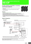
Provides simplicity and flexibility in connecting
serial devices to EtherCAT
• Mount to the NX-series EtherCAT Coupler Unit and connect various types of
serial devices.
• The serial line monitor on the Sysmac Studio helps easily and reliably
connect serial devices.
Features
•
•
•
•
•
•
•
Just 12 mm wide, saving space in your cabinet.
Three models are available with a choice of one RS-422A/485, one RS-232C, or two RS-232C ports.
Screwless push-in terminal block (1-port model) and D-Sub connector (2-port model) significantly reduce wiring work.
No-protocol communications are supported as the communications protocol.
The maximum baud rate is 230.4 kbps. The baud rate can be selected to match the connected serial devices.
The settings are backed up and saved in the EtherCAT Coupler Unit. This facilitates commissioning and maintenance.
The serial line monitor enables you to check the communications status with serial devices on the Sysmac Studio for easy and reliable startup
of the devices.
System Configuration
Support Software
Sysmac Studio
EtherCAT Master *
NJ-series CPU Unit or a master that you create inhouse
Connection to the peripheral
USB port or built-in
EtherNet/IP port on an
NJ-series CPU Unit
.xml
Built-in EtherCAT port
ESI Files
Support Software
Sysmac Studio
EtherCAT
Communications Cable
Ethernet cable
●EtherCAT Slave Terminal
NX-series
EtherCAT Coupler Unit
Peripheral USB Port
.xml
Connection to the peripheral
USB port on an EtherCAT
Coupler Unit
ESI Files
End Cover
NX Units
Communications
Interface Units
Serial line
* An EtherCAT Slave Terminal cannot be connected to any of the OMRON CJ1W-NC@81 or
CJ1W-NC@82 Position Control Units even though they can operate as EtherCAT masters.
Serial Communications Device
Sysmac is a trademark or registered trademark of OMRON Corporation in Japan and other countries for OMRON factory automation products.
EtherCAT® is a registered trademark of Beckhoff Automation GmbH for their patented technology.
EtherNet/IPTM, DeviceNetTM are trademarks of the ODVA.
Other company names and product names in this document are the trademarks or registered trademarks of there respective companies.
1
NX-CIF
Ordering Information
International Standards
• The standards are abbreviated as follows: U: UL, U1: UL(Class I Division 2 Products for Hazardous Locations), C: CSA, UC: cULus, UC1: cULus (Class I Division
2 Products for Hazardous Locations), CU: cUL, N: NK, L: Lloyd, CE: EC Directives, RCM: Regulatory Compliance Mark, and KC: KC Registration.
• Contact your OMRON representative for further details and applicable conditions for these standards.
Communications Interface Units
Unit type
Product Name
Serial interface
RS-232C
NX-series
communications
Interface Units
Communications
Interface Units
RS-422A/485
RS-232C
External
connection
terminals
Number of
serial ports
Screwless
Clamping
Terminal Block
1 port
D-Sub
connector
2 ports
Communications
protocol
Model
Standards
NX-CIF101
No-protocol
Signal lines
NX-CIF105
UL, CE, RCM, KC
NX-CIF210
Option
Product name
Specification
Model
Pins for 10 Units
Unit/Terminal Block Coding Pins
(30 terminal block pins and 30 Unit pins)
NX-AUX02
Standards
---
Specification
Product Name
Terminal Block *
No. of terminals
Terminal number
indications
Ground terminal
mark
Terminal current
capacity
16
A/B
Present
10 A
Model
NX-TBC162
Standards
---
* These options can be used with the NX-CIF101 and NX-CIF105. (They cannot be used with the NX-CIF210.)
Serial Line Monitor
On the Sysmac Studio, the monitor data is displayed in the CIF Serial Line Monitor tab page. The configuration of the CIF Serial Line Monitor tab
page is shown below. The data values are shown from left to right along a time scale. The left edge is the starting point of the monitor.
2
NX-CIF
General Specification
Item
Specification
Enclosure
Mounted in a panel.
Grounding method
Ground of 100 Ω or less.
If a conductive DIN Track is used, a Communications Interface Units is grounded through
the DIN Track from the System Power Supply Unit. If a non-conductive DIN Track is used,
a Communications Interface Units is grounded from the FG terminal.
Ambient operating
temperature
0 to 55°C
Ambient operating humidity 10% to 95% (with no condensation or icing)
Operating
environment
Atmosphere
Must be free from corrosive gases.
Ambient storage
temperature
-25 to 70°C (with no condensation or icing)
Altitude
2,000 m max.
Pollution degree
2 or less: Conforms to JIS B 3502 and IEC 61131-2.
Noise immunity
2 kV on power supply line (Conforms to IEC 61000-4-4.)
Overvoltage category
Category II: Conforms to JIS B 3502 and IEC 61131-2.
EMC immunity level
Zone B
Vibration resistance
Conforms to IEC 60068-2-6.
5 to 8.4 Hz with 3.5-mm amplitude, 8.4 to 150 Hz, Acceleration of 9.8 m/s2,
100 min in X, Y, and Z directions (10 sweeps of 10 min each = 100 min total)
Shock resistance
Conforms to IEC 60068-2-27. 147 m/s2, 3 times each in X, Y, and Z directions
Insulation resistance
20 MΩ min. between isolated circuits (at 100 VDC)
Dielectric strength
Applicable standards
510 VAC between isolated circuits for 1 minute with leakage current of 5 mA max.
cULus: Listed (UL508), ANSI/ISA 12.12.01, EC: EN 61131-2, RCM, and KC: KC Registration
3
NX-CIF
Specifications of Individual Units
NX-CIF101
Item
Specification
Number of ports
1
Communications ports
RS-232C
Communications protocol
No-protocol
Communications method
Full duplex
Signal lines *1
---
Baud rate [bps] *1
1,200, 2,400, 4,800, 9,600, 19,200, 38,400, 57,600, 115,200, or 230,400
Data length [bits] *1
7 or 8
Parity *1
Even, odd, or none
Start bits [bits]
Always 1.
Stop bits [bits] *1
1 or 2
Communications
Flow control *1
specifications
Flow control target *1
None, RS/CS flow control, or Xon/Xoff control
Send/receive, send only, or receive only
Initial RS signal value *1 *2
ON or OFF
Number of characters to determine
the end *1 *3
0 to 10,000 (in increments of 0.1 character))
0: The end is not detected.
Maximum communications
distance [m]
15 *4
Connection configuration
1:1
I/O refreshing method
Free-Run refreshing only
PDO data size [bytes] *1
Inputs or outputs: 4, 8, 12, 16, 20, 24, 28, 32, 36, 40, 44, 48, 52, 56, 60, 64, 68, 72,
76, or 80
Transmission buffering enable/disable setting *1
Enabled or disabled
Functions to back up data
Provided. *5
Terminating resistance setting
---
Isolation method
No isolation
Power consumption
900 mW max.
Weight
66 g max.
Installation orientation: 6 possible orientations
Restrictions: There are no restrictions.
Setting is possible in the Unit operation settings of the Sysmac Studio.
This is the value of the RS signal when the port enters the Operational state or immediately after the port is restarted. The initial value is
disabled when RS/CS flow control is set.
This setting is provided for communications protocols that assume the end of the data if data is not received for a specific period of time. For
example, if the number of characters to determine the end is set to 35, the end of the data will be assumed if data is not received for the time
required to receive 3.5 characters.
If the baud rate is set to higher than 19,200 bps, refer to the manual for the remote communications device.
The settings that are backed up are saved in memory in the Communications Coupler Unit. The settings that are backed up are not saved in
the Communications Interface Units.
Installation orientation and restrictions
*1.
*2.
*3.
*4.
*5.
4
NX-CIF
NX-CIF105
Item
Specification
Number of ports
1
Communications ports
RS-422A/485
Communications protocol
No-protocol
Communications method
Half duplex for two-wire connection, Full duplex for four-wire connection
Signal lines *1
Two lines or four lines
Baud rate [bps] *1
1,200, 2,400, 4,800, 9,600, 19,200, 38,400, 57,600, 115,200, or 230,400
Data length [bits] *1
7 or 8
Parity *1
Even, odd, or none
Start bits [bits]
Always 1.
Stop bits [bits] *1
1 or 2
Communications Flow control *1
specifications
Flow control target *1
None or Xon/Xoff control
Send/receive, send only, or receive only
Initial RS signal value *1 *2
ON or OFF
Number of characters to determine
the end *1 *3
0 to 10,000 (in increments of 0.1 character))
0: The end is not detected.
Maximum communications
distance [m]
1,200 *4
Connection configuration
1:N
Maximum value of N is 32.
You can change between two-wire and four-wire connections.
I/O refreshing method
Free-Run refreshing only
PDO data size [bytes] *1
Inputs or outputs: 4, 8, 12, 16, 20, 24, 28, 32, 36, 40, 44, 48, 52, 56, 60, 64, 68, 72,
76, or 80
Transmission buffering enable/disable setting *1
Enabled or disabled
Functions to back up data
Provided. *5
Terminating resistance setting
Possible
Isolation method
Power supply: transformer and photocoupler
Signals: Digital isolators
Power consumption
1,450 mW max.
Weight
69 g max.
Installation orientation: 6 possible orientations
Restrictions: There are no restrictions.
Setting is possible in the Unit operation settings of the Sysmac Studio.
This is the value of the RS signal when the port enters the Operational state or immediately after the port is restarted. The initial value is
disabled when RS/CS flow control is set. It is also disabled for the NX-CIF105.
This setting is provided for communications protocols that assume the end of the data if data is not received for a specific period of time. For
example, if the number of characters to determine the end is set to 35, the end of the data will be assumed if data is not received for the time
required to receive 3.5 characters.
The maximum total cable length for multidrop connections is 1,200 m.
The settings that are backed up are saved in memory in the Communications Coupler Unit. The settings that are backed up are not saved in
the Communications Interface Units.
Installation orientation and restrictions
*1.
*2.
*3.
*4.
*5.
5
NX-CIF
NX-CIF210
Item
Specification
Number of ports
2
Communications ports
RS-232C
Communications protocol
No-protocol
Communications method
Full duplex
Signal lines *1
---
Baud rate [bps] *1
1,200, 2,400, 4,800, 9,600, 19,200, 38,400, 57,600, 115,200, or 230,400
Data length [bits] *1
7 or 8
Parity *1
Even, odd, or none
Start bits [bits]
Always 1.
Stop bits [bits] *1
1 or 2
Communications
Flow control *1
specifications
Flow control target *1
None, RS/CS flow control, or Xon/Xoff control
Send/receive, send only, or receive only
Initial RS signal value *1 *2
ON or OFF
Number of characters to determine
the end *1 *3
0 to 10,000 (in increments of 0.1 character))
0: The end is not detected.
Maximum communications
distance [m]
15 *4
Connection configuration
1:1
I/O refreshing method
Free-Run refreshing only
PDO data size [bytes] *1
Inputs or outputs: 4, 8, 12, 16, 20, 24, 28, 32, 36, 40, 44, 48, 52, 56, 60, 64, 68, 72,
76, or 80
Transmission buffering enable/disable setting *1
Enabled or disabled
Functions to back up data
Provided. *5
Terminating resistance setting
---
Isolation method
No isolation
Power consumption
900 mW max.
Weight
91 g max.
Installation orientation: 6 possible orientations
Restrictions: There are no restrictions.
Setting is possible in the Unit operation settings of the Sysmac Studio.
This is the value of the RS signal when the port enters the Operational state or immediately after the port is restarted. The initial value is
disabled when RS/CS flow control is set.
This setting is provided for communications protocols that assume the end of the data if data is not received for a specific period of time. For
example, if the number of characters to determine the end is set to 35, the end of the data will be assumed if data is not received for the time
required to receive 3.5 characters.
If the baud rate is set to higher than 19,200 bps, refer to the manual for the remote communications device.
The settings that are backed up are saved in memory in the Communications Coupler Unit. The settings that are backed up are not saved in
the Communications Interface Units.
Installation orientation and restrictions
*1.
*2.
*3.
*4.
*5.
Version Information
Communications Interface Units
Model number
Unit version
Corresponding version *
EtherCAT Coupler Unit
NX-ECC20@
NJ-series CPU Unit
NJ501-@@@@ or NJ301-@@@@
Sysmac Studio
NX-CIF101
NX-CIF105
Ver.1.0
Ver.1.0
Ver.1.10
Ver.1.12
NX-CIF210
* Some Units do not have all of the versions given in the above table. If a Unit does not have the specified version, support is provided by the
oldest available version after the specified version. Refer to the user's manuals for the specific Units for the relation between models and
versions.
6
NX-CIF
External Interface
NX-CIF101/-CIF105
(B)
(B)
(C) (D) (E) (C)
(F)
(A)
(G)
(H)
Letter
Name
(C)
(E)
(C)
(I)
Description
This is where the markers are attached. OMRON markers are pre-installed at the factory.
You can also install commercially available markers.
(A)
Marker attachment location
(B)
NX bus connector
This connector is used to connect each Unit.
(C)
Unit hookup guides
These guides are used to connect two Units.
(D)
DIN Track mounting hooks
These hooks are used to mount the NX Unit to a DIN Track.
(E)
Protrusions for removing the Unit
These protrusions are to hold onto when you need to pull out the Unit.
The indicators show the current operating status of the Unit.
(F)
Indicators
(G)
Terminal block
This terminal block is used to connect the external serial communications device.
(H)
Unit specifications
The specifications of the Unit are given here.
(I)
DIN Track contact plate
This plate is connected internally to the functional ground terminal on the terminalblock.
7
NX-CIF
Terminal Block
(A)
Letter
(B)
A1
B1
A2
B2
A3
B3
A4
B4
A5
B5
A6
B6
A7
B7
A8
B8
(C)
(D)
Name
(A)
Terminal number indication
Description
The terminal numbers are given by column letters A and B, and row numbers 1 to 8.
The combination of the column and row gives the terminal numbers from A1 to A8 and B1 to B8.
(B)
Release hole
Insert a flat-blade screwdriver into this hole to connect and remove the wire.
(C)
Terminal hole
The wire is inserted into this hole.
(D)
Ground terminal mark
This mark indicates the ground terminals.
Applicable Terminal Blocks for Each Unit Model
Terminal Blocks
Model
Terminal Block
No. of terminals
Terminal number
indications
Ground terminal
mark
Terminal current
capacity
NX-CIF101
NX-TBC162
16
A/B
Present
10 A
NX-CIF105
NX-TBC162
16
A/B
Present
10 A
8
NX-CIF
Applicable Wires
Using Ferrules
If you use ferrules, attach the twisted wires to them.
Observe the application instructions for your ferrules for the wire stripping length when attaching ferrules.
Always use plated one-pin ferrules. Do not use unplated ferrules or two-pin ferrules.
The applicable ferrules, wires, and crimping tool are given in the following table.
Terminal types
Manufacturer
Terminals other
than ground
terminals
Phoenix
Contact
Applicable wire
(mm2 (AWG))
Ferrule model
AI0,34-8
0.34 (#22)
AI0,5-8
0.5 (#20)
Crimping tool
Phoenix Contact (The figure in parentheses is the applicable wire
size.)
CRIMPFOX 6 (0.25 to 6 mm2, AWG 24 to 10)
AI0,5-10
AI0,75-8
0.75 (#18)
AI0,75-10
AI1,0-8
1.0 (#18)
AI1,0-10
AI1,5-8
1.5 (#16)
AI1,5-10
Ground
terminals
Terminals other
than ground
terminals
Weidmuller
AI2,5-10
2.0 *1
H0.14/12
0.14 (#26)
H0.25/12
0.25 (#24)
H0.34/12
0.34 (#22)
H0.5/14
0.5 (#20)
Weidmueller (The figure in parentheses is the applicable wire size.)
PZ6 Roto (0.14 to 6 mm2, AWG 26 to 10)
H0.5/16
H0.75/14
0.75 (#18)
H0.75/16
H1.0/14
1.0 (#18)
H1.0/16
H1.5/14
1.5 (#16)
H1.5/16
*1. Some AWG 14 wires exceed 2.0 mm2 and cannot be used in the screwless clamping terminal block.
When you use any ferrules other than those in the above table, crimp them to the twisted wires so that the following processed dimensions are achieved.
8 to 10 mm
1.6 mm max. (except ground terminals)
2.0 mm max. (ground terminals)
2.4 mm max. (except ground terminals)
2.7 mm max. (ground terminals)
Using Twisted Wires/Solid Wires
If you use the twisted wires or the solid wires, use the following table to determine the correct wire specifications.
Terminals
Classification
Current capacity
Wire type
Twisted wires
Plated
2 A max.
All terminals except
ground terminals
Ground terminals
Greater than
2 A and 4 A or less
Possible
Greater than
4A
Possible
*1
---
Possible
Solid wire
Unplated
Plated
Unplated
Possible
Possible
Possible
Not
Possible
Possible
Possible
*1
Not
Possible
Possible
*2
Not
Possible
Possible
*2
Wire size
Conductor length
(stripping length)
0.08 to 1.5 mm2
AWG28 to 16
8 to 10 mm
2.0 mm2
9 to 10 mm
*1 Secure wires to the screwless clamping terminal block. Refer to the Securing Wires in the USER'S MANUAL for how to secure wires.
*2 With the NX-TB@@@1 Terminal Block, use twisted wires to connect the ground terminal. Do not use a solid wire.
Conductor length (stripping length)
<Additional Information> If more than 2 A will flow on the wires, use plated wires or use ferrules.
9
NX-CIF
NX-CIF210
(B)
(C)
(D)
(E)
(C)
(A)
(B)
(F)
(G)
(I)
Letter
Name
(H)
(C)
(E)
(C)
(J)
Description
This is where the markers are attached. OMRON markers are pre-installed at the factory. You
can also install commercially available markers.
(A)
Marker attachment location
(B)
NX bus connector
This connector is used to connect each Unit.
(C)
Unit hookup guides
These guides are used to connect two Units.
(D)
DIN Track mounting hooks
These hooks are used to mount the NX Unit to a DIN Track.
(E)
Protrusions for removing the Unit
These protrusions are to hold onto when you need to pull out the Unit.
(F)
Indicators
The indicators show the current operating status of the Unit.
(G)
D-Sub connector
This connector is used to connect the external serial communications device.
This is the D-Sub connector plug.
(H)
FG terminal
This is the external ground connection terminal. It is a screwless clamping terminal.
(I)
Unit specifications
The specifications of the Unit are given here.
(J)
DIN Track contact plate
This plate is connected internally to the functional ground terminal on the terminal block.
10
NX-CIF
Dimensions
(Unit: mm)
NX-CIF101 and NX-CIF105
14.1
0.55
12.0
1.5
104.5
100
1.5
65.2
71
80
NX-CIF210
4.5
77
16.1
1.5
71
100
(40)
61.2
21.2
9.9
5
1.5
5.8
17.2
30
32.1
Installation Heights
160
129
77
71
11
NX-CIF
Related Manuals
Man. No
W540
Model
NX-CIF@@@
Manual
NX-series
Communications Interface
Units User's Manual
Application
Description
Learning how to use
The hardware, setup methods, and functions of the
NX-series Communications NX-series Communications Interface Unit are
Interface Units
described.
12
Terms and Conditions Agreement
Read and understand this catalog.
Please read and understand this catalog before purchasing the products. Please consult your OMRON representative if you
have any questions or comments.
Warranties.
(a) Exclusive Warranty. Omron’s exclusive warranty is that the Products will be free from defects in materials and workmanship
for a period of twelve months from the date of sale by Omron (or such other period expressed in writing by Omron). Omron
disclaims all other warranties, express or implied.
(b) Limitations. OMRON MAKES NO WARRANTY OR REPRESENTATION, EXPRESS OR IMPLIED, ABOUT
NON-INFRINGEMENT, MERCHANTABILITY OR FITNESS FOR A PARTICULAR PURPOSE OF THE PRODUCTS. BUYER
ACKNOWLEDGES THAT IT ALONE HAS DETERMINED THAT THE
PRODUCTS WILL SUITABLY MEET THE REQUIREMENTS OF THEIR INTENDED USE.
Omron further disclaims all warranties and responsibility of any type for claims or expenses based on infringement by the
Products or otherwise of any intellectual property right. (c) Buyer Remedy. Omron’s sole obligation hereunder shall be, at
Omron’s election, to (i) replace (in the form originally shipped with Buyer responsible for labor charges for removal or
replacement thereof) the non-complying Product, (ii) repair the non-complying Product, or (iii) repay or credit Buyer an amount
equal to the purchase price of the non-complying Product; provided that in no event shall Omron be responsible for warranty,
repair, indemnity or any other claims or expenses regarding the Products unless Omron’s analysis confirms that the Products
were properly handled, stored, installed and maintained and not subject to contamination, abuse, misuse or inappropriate
modification. Return of any Products by Buyer must be approved in writing by Omron before shipment. Omron Companies shall
not be liable for the suitability or unsuitability or the results from the use of Products in combination with any electrical or
electronic components, circuits, system assemblies or any other materials or substances or environments. Any advice,
recommendations or information given orally or in writing, are not to be construed as an amendment or addition to the above
warranty.
See http://www.omron.com/global/ or contact your Omron representative for published information.
Limitation on Liability; Etc.
OMRON COMPANIES SHALL NOT BE LIABLE FOR SPECIAL, INDIRECT, INCIDENTAL, OR CONSEQUENTIAL DAMAGES,
LOSS OF PROFITS OR PRODUCTION OR COMMERCIAL LOSS IN ANY WAY CONNECTED WITH THE PRODUCTS,
WHETHER SUCH CLAIM IS BASED IN CONTRACT, WARRANTY, NEGLIGENCE OR STRICT LIABILITY.
Further, in no event shall liability of Omron Companies exceed the individual price of the Product on which liability is asserted.
Suitability of Use.
Omron Companies shall not be responsible for conformity with any standards, codes or regulations which apply to the
combination of the Product in the Buyer’s application or use of the Product. At Buyer’s request, Omron will provide applicable
third party certification documents identifying ratings and limitations of use which apply to the Product. This information by itself
is not sufficient for a complete determination of the suitability of the Product in combination with the end product, machine,
system, or other application or use. Buyer shall be solely responsible for determining appropriateness of the particular Product
with respect to Buyer’s application, product or system. Buyer shall take application responsibility in all cases.
NEVER USE THE PRODUCT FOR AN APPLICATION INVOLVING SERIOUS RISK TO LIFE OR PROPERTY OR IN LARGE
QUANTITIES WITHOUT ENSURING THAT THE SYSTEM AS A WHOLE HAS BEEN DESIGNED TO ADDRESS THE RISKS,
AND THAT THE OMRON PRODUCT(S) IS PROPERLY RATED AND INSTALLED FOR THE INTENDED USE WITHIN THE
OVERALL EQUIPMENT OR SYSTEM.
Programmable Products.
Omron Companies shall not be responsible for the user’s programming of a programmable Product, or any consequence
thereof.
Performance Data.
Data presented in Omron Company websites, catalogs and other materials is provided as a guide for the user in determining
suitability and does not constitute a warranty. It may represent the result of Omron’s test conditions, and the user must correlate
it to actual application requirements. Actual performance is subject to the Omron’s Warranty and Limitations of Liability.
Change in Specifications.
Product specifications and accessories may be changed at any time based on improvements and other reasons. It is our
practice to change part numbers when published ratings or features are changed, or when significant construction changes are
made. However, some specifications of the Product may be changed without any notice. When in doubt, special part numbers
may be assigned to fix or establish key specifications for your application. Please consult with your Omron’s representative at
any time to confirm actual specifications of purchased Product.
Errors and Omissions.
Information presented by Omron Companies has been checked and is believed to be accurate; however, no responsibility is
assumed for clerical, typographical or proofreading errors or omissions.
2015.6
In the interest of product improvement, specifications are subject to change without notice.
OMRON Corporation
Industrial Automation Company
http://www.ia.omron.com/
(c)Copyright OMRON Corporation 2015 All Right Reserved.