1
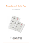
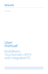
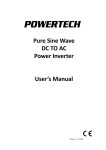
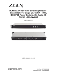
 Control Panel User Manual 1. Introduction This document describes how to run the Blueray/STB control panel together with the PC test software. It also exposes some firmware behaviors. The hardware of control panel consists of nine keys, four 7‐segment LEDs, one IR receiver, and one signal strength LED. It interfaces with the host through UART. Figure 1 Blueray/STB control panel The control panel operates in two power mode modes: normal mode and sleep mode. In normal mode, the control panel can respond to any of on‐board key‐presses and UART commands from host. In sleep mode, all keys except on/off key are not detectable, and UART receiving is disabled. On/off key and specific IR code can wake it up, but it’s the host which determines the control panel’s working mode via UART command. When the control panel detects key‐press, it will send the key info to the host and the host responds accordingly. All the working statuses like the power mode, volume and channel are maintained by the host. The control panel only remembers the power mode. 2. Hardware Setup 2.1 The hardware setup consists of PC, the control panel, one USB power cable and one straight serial
cable.
Version 1.0 Figure 2 Test hardware
2.2 Connect the serial ports between PC and the control panel.
3. Test Software Setup 3.1 Open control_panel_host.exe on the PC and the dialog will be as below:
Figure 3 Test software dialog
3.2 Select the serial port which is connected to the control panel, and open the port.
Version 1.0 4. Test the Functions 4.1 Plug in USB power cable and the 7-segment will display “LOAD”.
Figure 4 7‐segment LED display after power on
4.2 Press on/off key to toggle power mode. The host will send turn on/off packet to the control panel to
set the power mode. When the control panel is in off mode and on/off key is pressed, the host must
reply turn on command within 50ms, otherwise the control panel will go back to sleep again and
thereafter all UART commands will be lost.
4.3 Short and long press volume+ and volume- keys to set the volume. In long press, key packet is sent
out every 500ms.
Figure 5 7‐segment LED display when volume key is pressed
Version 1.0 4.4 Short and long press channel+ and channel- keys to set the channel. In long press, key packet is sent
out every 500ms.
Figure 6 7‐segment LED display when channel key is pressed
4.5 Press play button. The host will start a timer and return elapsed time every 1 second.
4.6 Press pause button. The host will stop the timer and return current elapsed time.
Figure 7 7‐segment LED display when play/pause key is pressed
4.7 Press stop button. The host will reset the timer and return “00:00”.
4.8 Press menu button. The host will return “LOAD”.
Version 1.0 4.9 In power off mode, press on button on the remote control to turn on the control panel. It will have the
same effect as the on/off key. The control panel supports NEC 6121 code. Currently three IR codes
are accepted as the wake-up signal:
a. system code: 0xFD02
data: 0x0D
b. system code: 0x08E6
data: 0x43
c. system code: 0x01FD
data: 0xDC
4.10
When the control panel is in power on mode, click “Toggle on/off” button on the test software
dialog to turn off the control panel.
4.11
When the control panel is in power on mode, click “Dimming” button to set the brightness of the
signal strength LED on the control panel.
Figure 8 Display in test software dialog 5. Power Measurements 5.1 MCU current consumption on Vcc Pin is measured:
a. Normal mode: 2.4mA
b. Sleep mode: 0.2uA
Version 1.0 5.2 Current is measured at the 5V input before the DC-DC regulator. The total current is 6.6mA (normal
mode) and 4.4mA (sleep mode) with following breakdown:
a. MCU: 2.2mA (normal mode) or 0.2uA (sleep mode)
b. IR receiver: 2.4mA
c. UART level shifter: 0.3mA
d. 7-segment LED display IC and other circuits: 1.7mA
Version 1.0