1
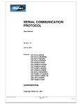
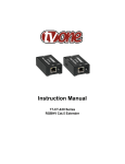
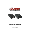
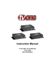
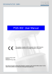
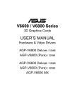
®
EXT-VGA-2-DVISP
User Manual
ASKING FOR ASSISTANCE
Technical Support:
Telephone
Fax
(818) 772-9100
(800) 545-6900
(818) 772-9120
Technical Support Hours:
8:00 AM to 5:00 PM (PST) Monday thru Friday Pacific Time
Write To:
Gefen, LLC
c/o Customer Service
20600 Nordhoff St
Chatsworth, CA 91311
www.gefen.com
[email protected]
Notice
Gefen, LLC reserves the right to make changes in the hardware, packaging, and
any accompanying documentation without prior written notice.
VGA to DVI Scaler Plus is a trademark of Gefen, LLC
© 2013 Gefen, LLC. All rights reserved.
All trademarks are the property of their respective owners.
Rev A8
CONTENTS
1
Introduction
2
Operation Notes
3
Features
3
Package Includes
4
Panel Layout
5
Panel Descriptions
6
Connecting the VGA to DVI Scaler Plus
6
Wiring Diagram
7
Menu System
7
PC Menu
8
Color Menu
9
Output Menu
10
Output Resolutions
11
OSD Menu
12
Information Menu
12
Resetting the Scaler
13 Specifications
14 Warranty
INTRODUCTION
Congratulations on your purchase of the VGA to DVI Scaler Plus. Your complete
satisfaction is very important to us.
Gefen
Gefen delivers innovative, progressive computer and electronics add-on solutions
that harness integration, extension, distribution and conversion technologies.
Gefen’s reliable, plug-and-play products supplement cross-platform computer
systems, professional audio/video environments and HDTV systems of all sizes
with hard-working solutions that are easy to implement and simple to operate.
The Gefen VGA to DVI Scaler Plus
The VGA to DVI Scaler Plus connects traditional analog video graphic cards (VGA)
to DVI compliant digital monitors. The VGA to DVI Scaler PLUS enables users to
connect laptops or legacy PC computers equipped with HD-15 video connections
to the DVI (digital visual interface) video display format. The VGA to DVI Scaler
Plus will also work with component video sources such as DVD players and set top
boxes. You can even add a converter cable to achieve HDMI video, or go further
and merge external audio sources with the HDMI signal to create HDMI video with
embedded digital audio.
How It Works
Simply connect the supplied VGA (M-F) cable to the input side of the VGA to DVI
Scaler PLUS. Then connect the DVI monitor or projector to the DVI output of the
VGA to DVI Scaler Box. The converter generates the compatible analog to digital
conversion signals to make the connection between the analog input and the
digital output work. Navigation through the menu is easily done via the buttons in
the front of the unit.
1
OPERATION NOTES
READ THESE NOTES BEFORE INSTALLING OR
OPERATING THE VGA TO DVI SCALER PLUS
•
The VGA to DVI Scaler Plus provides an auto-adjust (auto-sync) feature
each time the VGA source is connected to the VGA to DVI Scaler Plus.
The VGA to DVI Scaler Plus will also perform an auto-adjust during a hotplug event, a power-cycle event, or if the resolution is changed.
2
FEATURES
Features
•
The input is analog PC or HDTV signal in the format of either RGBHV,
YPbPr or YCbCr.
•
The output is digital+analog PC or HDTV signal in the format of digital
RGBHV bit stream plus analog RGBHV, known as DVI-I (Integrated digital
and analog).
•
The input resolution is automatically detected while the output resolution
and refresh rate can be selected through OSD menu and front panel push
buttons.
•
48 MB frame memory for frame rate conversion.
•
Output picture adjustment on brightness, contrast, color, RGB level and H-V
position.
•
DVI output enables an all digital rendering of video without the losses
associated with an analog interface and is ideal for use with digital display
such as LCD, Plasma and DLP projectors.
•
High performance Scaler that converts and scales analog RGB inputs to
DVI-I (digital or analog) outputs
•
Output resolution can be easily selected using the OSD (On Screen Display)
•
Supports input/output computer resolutions up to 1920x1200 / 2048 x 1080
(2K) at 60Hz
•
Supports HDTV resolution up to 1080p as input and output.
•
Supports DDWG standard for DVI compliant monitors
•
Aspect ratio control for native and full view modes
•
Controllable by optional IR remote control
Package Includes
(1) VGA to DVI Scaler Plus
(1) 6 ft. VGA cable (M - F)
(1) 5V DC Power Supply
(1) Quick-Start Guide
3
PANEL LAYOUT
Front Panel
1
2
3
Back Panel
5
7
4
6
4
PANEL DESCRIPTIONS
1
DVI Out
Connect a DVI cable from this port to a DVI display.
2
Menu
Press this button to display / hide the built-in Menu System.
3
Navigation (- / +)
Press these buttons to change values within the Menu System, such as
brightness, color, output resolutions, etc. These buttons are also used to
navigate the Menu System. Depress and hold the Menu and the - button to
reset the Scaler.
4
IR
Not used.
5
VGA In
Connect a VGA cable from this port to the VGA source.
6
5V DC
Connect the included 5V DC locking power supply to this receptacle.
7
Power
This LED will turn bright red once the included 5V DC power supply has
connected to the unit and the power supply has been connected to an available
electrical outlet.
5
CONNECTING THE VGA TO DVI SCALER PLUS
How to Connect the VGA to DVI Scaler Plus
1.
Connect the included VGA cable from the VGA source to the VGA In
connector on the Scaler.
2.
Connect a DVI cable between the DVI Out connector on the Scaler and the
DVI display.
3.
Connect the 5V DC power supply to the VGA to DVI Scaler Plus, then
connect the AC power cord from the power supply to an available electrical
outlet. The LED on the VGA to DVI Scaler Plus will turn bright red indicating
that the unit is powered.
4.
Power-on both the VGA source and the DVI display.
Wiring Diagram for the VGA to DVI Scaler Plus
DVI CABLE
VGA CABLE
VGA Source
Scaler
DVI Display
EXT-VGA-2-DVISP
WARNING: This product should always be connected to a
grounded electrical socket.
6
MENU SYSTEM
PC Menu
To access the PC Menu, press the Menu button on the front panel.
Use the + or - buttons to highlight the PC Menu icon. Press the Menu
button to enter the PC Menu. Use the + or - buttons to scroll through each of
the parameters. After selecting the desired parameter, press the Menu button to
make changes. Use the + or - buttons to increase or decrease the values. Press
the Menu button to accept the settings.
Contrast
Adjusts the Contrast by increments of 1. Minimum value: 1, Maximum value:
100.
Brightness
Adjusts the Brightness by increments of 1. Minimum value: 1, Maximum value:
100.
H-Pos
Specifies the horizontal position of the input signal.
V-Pos
Specifies the vertical position of the input signal.
Clock
Adjusts the video input clock to bring the picture into focus.
7
MENU SYSTEM
Phase
Adjusts the phase to bring the picture into focus.
Scale
Sets the scaling adjustment. Options are: Full, Overscan, Underscan, Letterbox
U.S. (Underscan), PanScan U.S. (Underscan), Letterbox Full, and PanScan Full.
Exit
Returns control to the Menu System.
Color Menu
To access the Color Menu, press the Menu button on the front panel.
Use the + or - buttons to highlight the Color Menu icon. Press the Menu
button to enter the Color Menu. Use the + or - buttons to scroll through each of
the parameters. After selecting the desired parameter, press the Menu button to
make changes. Use the + or - buttons to increase or decrease the values. Press
the Menu button to accept the settings.
Color Temp.
•
Normal
Use for general content.
•
Warm
Red-shifts RGB values for a warmer video color.
8
MENU SYSTEM
•
Cool
Blue-shifts RGB values for a cooler video color.
•
User
Allows individual adjustment of Red, Green, and Blue color components.
Red
Adjusts the Red value by increments of 1. Minimum value: 1, Maximum value:
100.
Green
Adjusts the Green value by increments of 1. Minimum value: 1, Maximum value:
100.
Blue
Adjusts the Blue value by increments of 1. Minimum value: 1, Maximum value:
100.
Exit
Exits the Color Menu and returns control to the Main Menu.
Output Menu
To access the Output Menu, press the Menu button on the front panel.
Use the + or - buttons to highlight the Output Menu icon. Press the Menu
button to enter the Output Menu. Use the + or - buttons to select an output
resolution. Press the Menu button to set the new output resolution.
9
MENU SYSTEM
Output Resolutions
VGA
480i
576i
WXGA
SVGA
480p
576p
WSXGA
XGA
720p60
720p50
WUXGA
SXGA
1080i60
1080i50
UXGA
1080p60
1080p50
2K
SXGA+
APPLE
NATIVE*
Exit
* The Native option will select the native resolution of the connected display based
on the EDID from the display.
If a resolution that is not supported by the display is selected, then the
output signal will no longer be visible. If this occurs, reset the Scaler
using the procedure outlined on page 12.
Exit
Exits the Output Menu and returns control to the Main Menu.
10
MENU SYSTEM
OSD Menu
Use the + or - buttons to highlight the OSD Menu icon. Press the Menu button to
enter the OSD Menu. Use the + or - buttons to highlight the desired parameter.
Press the Menu button to make changes. Use the + or - buttons to change the
values. Press the Menu button to accept the changes.
H-Position (Horizontal Position)
Adjusts the horizontal position on the Menu System on the screen. Minimum value:
1, Maximum value: 100.
V-Position (Vertical Position)
Adjusts the vertical position of the Menu System on the screen. Minimum value: 1,
Maximum value: 100.
TimeOut
Adjusts the amount of time (in seconds) before the OSD automatically closes.
Minimum value: 1, Maximum value: 100.
Background
Sets the transparency level of the OSD background. Minimum value: 0, Maximum
value: 8.
Remote Channel
Sets the IR channel for use with the optional IR Remote Control Unit (Gefen part no.
EXT-RMT-SR-IR). Minimum value: 0, Maximum value: 3.
Exit
Exits the OSD Menu and returns control to the Main Menu.
11
MENU SYSTEM
Information Menu
To access the Information Menu, press the Menu button on the front panel.
Use the + or - buttons to highlight the Information Menu icon.
Resetting the Scaler
Resetting the Scaler will reset the output resolution to the native resolution of the
display. Should you need to reset the scaler, do the following:
1.
Hold down the MENU button and remove the power supply.
Note: The MENU button does not work without the source plugged in.
2.
Wait three seconds and plug the power supply into the unit.
3.
Once unit is powered on, let go of the MENU button.
4.
After three seconds, the scaler will reset to the displays native resolution.
Press and hold while
connecting power
12
SPECIFICATIONS
Maximum Pixel Clock........................................................................165MHz (DVI)
Video Amplifier Bandwidth.............................................................. 350MHz (VGA)
Input Sync Signal................................................................................ 5V p-p (TTL)
Horizontal Frequency Range................................................................. 15 - 70kHz
Vertical Frequency Range..................................................................... 30 - 170Hz
Video Input Connector........................................................ (1) VGA HD-15, female
Video Output Connector..................................................... (1) DVI-I 29 pin, female
Power Supply.................................................................................................5V DC
Power Consumption............................................................................. 10W (max.)
Operating Temperature............................................... 0˚ to +40˚C / +32 to +104 ˚F
Storage Temperature....................................................-20 to +60˚C / -4 to +140 ˚F
Relative Humidity......................................................... 20 to 90%, non-condensing
Dimensions............................................................................5.8” W x 4.1” D x 1” H
Shipping Weight.............................................................................................. 3 lbs
13
WARRANTY
Gefen warrants the equipment it manufactures to be free from defects in material
and workmanship.
If equipment fails because of such defects and Gefen is notified within two (2)
years from the date of shipment, Gefen will, at its option, repair or replace the
equipment, provided that the equipment has not been subjected to mechanical,
electrical, or other abuse or modifications. Equipment that fails under conditions
other than those covered will be repaired at the current price of parts and labor in
effect at the time of repair. Such repairs are warranted for ninety (90) days from
the day of reshipment to the Buyer.
This warranty is in lieu of all other warranties expressed or implied, including
without limitation, any implied warranty or merchantability or fitness for any
particular purpose, all of which are expressly disclaimed.
1.
Proof of sale may be required in order to claim warranty.
2.
Customers outside the US are responsible for shipping charges to and from
Gefen.
3.
Copper cables are limited to a 30 day warranty and cables must be in their
original condition.
The information in this manual has been carefully checked and is believed to
be accurate. However, Gefen assumes no responsibility for any inaccuracies
that may be contained in this manual. In no event will Gefen be liable for
direct, indirect, special, incidental, or consequential damages resulting from
any defect or omission in this manual, even if advised of the possibility of such
damages. The technical information contained herein regarding the features and
specifications is subject to change without notice.
For the latest warranty coverage information, refer to the Warranty and Return
Policy under the Support section of the Gefen Web site at www.gefen.com.
PRODUCT REGISTRATION
Please register your product online by visiting the Register Product page
under the Support section of the Gefen Web site.
14
Rev A8
Pb
This product uses UL listed or CE listed power supplies.