Download 2 - RO INSTALATII

Transcript
ST320RF Manual
Version 005:Layout 1
21/10/10
15:32
Page 1
2
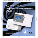
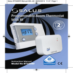
S-Series Digital Thermostat
Model No ST320RF
Instruction Manual
ST320RF Manual
2
Version 005:Layout 1
21/10/10
15:32
Page 2
ST320RF INSTRUCTION MANUAL
ST320RF Manual
Version 005:Layout 1
21/10/10
15:32
Page 3
PRODUCT COMPLIANCE
This product complies with the essential requirements of the following EC Directives:
•
•
•
Electro-Magnetic Compatibility directive 2004/108/EC
Low Voltage Directive 2006/95/EEC
EC Marking directive 93/68/EEC
SAFETY INFORMATION
These instructions are applicable to the Salus Controls model stated on the front cover of this manual
only, and must not be used with any other make or model.
These instructions are intended to apply in the United Kingdom only, and should be followed along
with any other statutory obligations.
This accessory must be fitted by a Competent person, and installation must comply with the guidance
provided in the current editions of BS7671 (IEE Wiring Regulations) and Part ‘P’ of the Building
Regulations. Failure to comply with the requirements of these publications could lead to prosecution.
When fitting the receiver always isolate the AC Mains supply before opening or removing the unit from
the wall or wall box.
When fitting batteries don’t mix old and new batteries together. Do not use rechargable batteries.
Please leave these instructions with the end user where they should be kept in a safe place for future
reference.
ST320RF INSTRUCTION MANUAL
3
ST320RF Manual
Version 005:Layout 1
21/10/10
15:32
Page 4
INTRODUCTION
A thermostat is a device that is used to switch the heating system in your home on and off as needed. It
works by sensing the air temperature and switching on the heating when the air temperature falls below
the thermostat setting, and switching it off once the set temperature has been reached.
The ST320RF from Salus Controls is a stylish and accurate electronic thermostat with a large, easy to
read LCD display. The thermostat has been specifically designed to be used Volt Free. Unlike ordinary
single unit design thermostats, this is a new type of thermostat separating the operational functions
into two units.
The Receiver is used for wiring connections and heat on/off
control. The Control Centre provides the user interface and
temperature sensing / control. The two units are linked together
by a Radio Frequency (RF) signal.
The use of the revolutionary Touch Ring technology makes for
simple usage, and is coupled with a unique, smart design. The
LCD display will show the current room temperature and the ‘one
touch’ operation makes the ST320RF easy to operate.
FEATURES
• Touch Ring Technology
• Large LCD with white backlight
• Stylish Casing
• Volt Free Contacts
• Intelligent Communication Technology
4
•
•
•
•
Battery Powered with Replacement Indicator
Frost Protection
Burner on symbol
Secure RF Transmission
(one million unique RF address codes)
ST320RF INSTRUCTION MANUAL
ST320RF Manual
Version 005:Layout 1
21/10/10
15:32
Page 5
INSTALLATION
Please read the important safety information at the start of this manual before you start to install the device.
The ideal position to locate the Control Centre is about 1.5m above floor level. It should be mounted in a
location where the thermostat is accessible, reasonably lit and free from extremes of temperature and
draughts. Do not mount the thermostat on an outside wall, above a radiator or in a location where it may
be subjected to direct sunlight.
To ensure trouble free operation of the Radio Frequency (RF) signal, always ensure that the programmable
thermostat is mounted away from any possible sources of interference (such as radios, TV sets, computers,
etc.), and is not mounted on or in close proximity to large metal objects. Installing the ST320RF in enclosed
areas such as cellars and basements is not recommended.
BOILER
RECEIVER
COM N/O
L
N
N MAINS
L FEED
Thermostat loop (Remove link)
Live Feed
L
SL
L
N
ST320RF INSTRUCTION MANUAL
E
5
ST320RF Manual
Version 005:Layout 1
21/10/10
15:32
Page 6
CONNECTING THE ST320RF RECEIVER
NOTE: All electrical installation work should be carried out by a suitably qualified Electrician or other
competent person. If you are not sure how to install this digital thermostat consult either with a qualified
electrician, heating engineer or your boiler / heating system supplier for advice on how to continue.
The ST320RF Receiver should be mounted in a suitable location that is both accessible for the connection
of mains and control wiring, and allows good reception of the RF signal. The Receiver needs a 230V AC
mains supply to operate, and this should be fused appropriately (16A max.). The Receiver should be
mounted in a location where it will not come into contact with water, moisture or condensation. Please
be reminded that touch can be held up by condensation on the touch ring surface and can reduce
sensitivity.
There are few electrical connections required to the ST320RF, and these connections should be made to
the terminal block inside the Receiver. No Earth connection is required for the correct and safe operation
of the ST320RF, but a parking terminal is provided to connect an Earth wire if one is present.
These electrical connections are shown in the table below:
Terminal
Function
COM
Common Contact (volt free input)
NO
Normally Open Contact (volt free output)
Earth Parking (No electrical connection)
6
L
Incoming Mains - Live
N
Incoming Mains - Neutral
ST320RF INSTRUCTION MANUAL
ST320RF Manual
Version 005:Layout 1
21/10/10
15:32
Page 7
INSTALLING AND REPLACING BATTERIES
Installing or replacing the ST320RF Control Centre batteries is
a straightforward operation, but does require you to open the
case of the thermostat.
To open the ST320RF case, undo the securing screw on the
bottom of the case (just to the right of the hole for the Reset
Button):
After undoing the screw pull it forward until the screw stops
moving, then carefully separate the two halves of the case
by gently pulling in an upwards direction. Once the case has
been separated, the batteries should be visible:
Ensure that the batteries are inserted correctly, paying
careful attention to the polarity markings on the battery and
next to the battery holders. After inserting the batteries, refit
the ST320RF case and retighten the securing screw.
ST320RF INSTRUCTION MANUAL
7
ST320RF Manual
Version 005:Layout 1
21/10/10
15:32
Page 8
PAIRING THE ST320RF RECEIVER AND CONTROL CENTRE
It is important to correctly pair both the Receiver and Control Centre to ensure that the RF address codes
are matched and that reliable communication is established between the units. Please follow the
instructions below to ensure that the units are configured correctly.
ON THE RECEIVER:
Press and hold the SYNC button to allow the Receiver to enter the learning mode. The Red SYNC LED will
turn on to indicate it is ready to receive a signal and pair with another unit.
While the signal is being received, the SYNC LED will turn on until the pairing has completed successfully;
the SYNC LED will then turn off and the Green Power LED will turn on again. The Control Centre will
continue to transmit a pairing signal for 10 minutes before returning to NORMAL mode.
8
ST320RF INSTRUCTION MANUAL
ST320RF Manual
Version 005:Layout 1
21/10/10
15:32
Page 9
ON THE CONTROL CENTRE:
The Arrow key is not active when the ST320RF is in NORMAL mode. To access the Menu screens, press
the OK key once. The first menu displayed is the FROST menu:
Use the Touch Ring to scroll through the Menus, and press the OK key to select the PAIR menu:
You can scroll through the menus in either direction (forwards or backwards) depending on the direction you
move your finger around the Touch Ring. The menus are displayed in the order shown in the picture above.
ST320RF INSTRUCTION MANUAL
9
ST320RF Manual
Version 005:Layout 1
21/10/10
15:32
Page 10
After selecting the PAIR Menu, PAIR and the RF icon are displayed.
Press the OK key to start sending the RF address code to the Receiver.
The ST320RF Control Centre display will change to show a rundown timer:
The unit counts down for a period of 10 minutes, with the RF Signal indicator flashing while the signal
is being transmitted. The RF address code will be generated randomly and the Control Centre will
transmit the signal every second for the full 10 minutes until:
10
ST320RF INSTRUCTION MANUAL
ST320RF Manual
•
•
•
Version 005:Layout 1
21/10/10
15:32
Page 11
The Arrow key is pressed to return to the previous display
The OK key is pressed to return to NORMAL mode
The 10 minute timer runs out
Note that the Receiver must be already in learning mode BEFORE attempting to access the PAIR menu
on the Control Centre. If the Red SYNC LED has not turned off after 10 minutes, repeat the whole pairing
process.
Pressing the Reset button on the Control Centre and the Receiver will clear the RF address code and
generate a new default code which will be saved into the internal memory of the unit; there is no need
to re-pair the Receiver and Control Centre. This is a quick and easy way to directly link the units in many
applications.
Replacing the Control Centre batteries will not affect the RF code setting. Pressing and holding the SYNC
button on the Receiver will however clear the RF address code saved into the internal memory, and
switch the Receiver into learning mode, as previously described.
ST320RF INSTRUCTION MANUAL
11
ST320RF Manual
Version 005:Layout 1
21/10/10
15:32
Page 12
Testing the RF Transmission
It is important to site both the Receiver and Control Centre in locations where the RF signal cannot be
interrupted.
The receiving range between Control Centre and Receiver is 100 metres in open air, however many
factors can affect the RF transmission and shorten the operating distance, e.g. shielding by thick walls,
foil back plasterboard, metal objects such as filing cabinets, general RF interference, and so on.
The operating range is generally around 30 metres, which is large enough for most household
applications, but it is advisable to test the RF transmission from the intended Control Centre location to
the Receiver location before fixing the Control Centre to the wall. If you are unable to get a stable RF
connection between the Receiver and Control Centre, check that the Receiver is both switched on and
has a mains supply (green LED lit).
The RF communication is one way, from the Control Centre to the Receiver – the Receiver does not send
any signal back to the Control Centre.
The RF signal indicator
only flashes once when a signal is being transmitted. Once the Receiver
has established communication successfully, the green Power LED will flash for 4 seconds to indicate
the process has completed correctly.
It will transmit only when there is a need to control the heating system.
12
ST320RF INSTRUCTION MANUAL
ST320RF Manual
Version 005:Layout 1
21/10/10
15:32
Page 13
RECEIVER LED INDICATORS
The LED indicators on the ST320RF Receiver are designed to give a clear and easily understood
indication of the current state of the system.
The various LED signal combinations and descriptions of what they indicate are shown in the table
below:
LED
State
Indication
Blue
Flashing
once per
second
Receiver is in Automatic mode and system is calling for heat.
Blue
Off
Receiver is in Automatic mode and system is NOT calling for heat
Blue
On (Not Flash)
Receiver is in Manual mode and system is calling for heat
Green
On
Power is on
Green
Flashing
for 4
seconds
Receiver has received correct RF address and Command
signal when in Failsafe mode
Red
On and
flashing
Receiver is either ready to receive a new RF address code in SYNC mode,
or has failed to store the new RF address code when in SYNC mode
Yellow
On
Receiver is in Failsafe mode after no RF signal received for over 1 hour
ST320RF INSTRUCTION MANUAL
13
ST320RF Manual
Version 005:Layout 1
21/10/10
15:32
Page 14
AFTER INSTALLATION
After completing installation and powering up the ST320RF for the first time the programmable
thermostat will behave in the following way:
All the indicators on the display and the backlight will be turned on. After two seconds, the display will
change to show the currently installed firmware version.
The ST320RF will then operate in NORMAL mode and display the current room temperature.
All programmable thermostat settings will have been returned to default values.
If the Reset Button is pressed, the ST320RF will behave in the same way as described above, except that
any previously saved user settings stored in the internal memory will be deleted and overwritten with
the default settings.
14
ST320RF INSTRUCTION MANUAL
ST320RF Manual
Version 005:Layout 1
21/10/10
15:32
Page 15
USER INTERFACE AND CONTROLS
The status and operation of the ST320 is clearly
shown on the large backlit Liquid Crystal Display (LCD).
The display consists of a combination of symbols and
alphanumeric displays. The top row is a set of status
symbols, the centre row is used to indicate temperature
(in Celsius), and the bottom row is an alphanumeric
display for menu and status messages.
The status symbol functions are:
Indicator
Description
Function
RF Signal indicator
(Not used with ST320)
Indicates the unit is transmitting a wireless signal
Touch Lock indicator
Indicates touch lock is activated
Heat Mode indicator
Indicates heating output is turned on.
Frost Mode indicator
Indicates frost setting is turned on
Battery Status
Indicates battery is low
ST320RF INSTRUCTION MANUAL
15
ST320RF Manual
Version 005:Layout 1
21/10/10
15:32
Page 16
There are few user controls for the ST320RF, making the
thermostat very easy to operate. The controls on the Control
Centre are a Touch Ring (which surrounds the user display), two
touch sensitive buttons, a reset button and a slide operated switch
mounted on the side of the thermostat. The ST320RF Receiver has
only two slide switches, a Sync button and a Reset button.
These controls are shown below, along with a description of each
of their functions:
USER CONTROL FUNCTION SUMMARY:
Key / Operation
Functions
Touch Ring (move clockwise)
Increases the set temperature and scrolls down the
menu selection
Decreases the set temperature and scrolls up
the menu selection
Enters Menu or confirms a menu selection
Single touch- sets the unit back 1 step.
Hold for 2 seconds sets unit back to normal mode
Resets the thermostat to default (original factory) settings
Activates and deactivates the key lock function
(prevents accidental changes)
Touch Ring (move anti- clockwise)
OK Key
Arrow (Back) Key
Reset Button
Slide Switch
16
ST320RF INSTRUCTION MANUAL
ST320RF Manual
Version 005:Layout 1
21/10/10
15:32
Page 17
The status of the ST320RF Receiver is indicated by the use of two
bi-colour Light Emitting Diodes (LEDs). The status indicators are:
Indicator
Colour
Operating Function
Blue / Yellow
Blue
Heat call mode
Yellow
Failsafe mode
Green / Red
Green
Power on
Red
SYNC mode
User Control Function Summary – ST320RF Receiver
Key/Operation
Functions
Auto
Sets Receiver to Automatic mode (default setting)
Manual
Sets Receiver to Manual mode
On
Means the relay output is always on
Cycle
Switches Receiver output on and off in a 15 minute cycle (4 minutes on, 11 minutes off)
Off
Means the relay output is always off
SYNC Button
Enables RF signal synchronisation with ST320RF Control Centre
Reset Button
Resets the Receiver to default (original factory) settings
ST320RF INSTRUCTION MANUAL
17
ST320RF Manual
Version 005:Layout 1
21/10/10
15:32
Page 18
OPERATION
The ST320RF is configured and adjusted by the use of an innovative
and stylish Touch Ring, and two touch sensitive buttons. The Touch
Ring surrounds the thermostat display, and is operated very easily by
moving your finger around the ring.
The backlit Liquid Crystal Display (LCD) gives a highly visible, easily
readable indication of the thermostat status.
REVIEWING THE SET TEMPERATURE
If you press the Touch Ring anywhere except the OK and Arrow keys when
the ST320RF is in NORMAL mode (NORMAL mode is when the thermostat is
displaying the room temperature), you can check the set temperature setting.
This will display the current set temperature. The set temperature will be
displayed for two seconds before the LCD changes to display the room
temperature again.
18
ST320RF INSTRUCTION MANUAL
ST320RF Manual
Version 005:Layout 1
21/10/10
15:32
Page 19
If the ST320RF is operating in Frost Mode the LCD will display both the room
temperature and also the Frost Mode indicator . To turn off FROST mode, select
the FROST menu and then by using the Touch Ring scroll to the OFF setting. OFF
will then be displayed on the LCD.
After pressing the Touch Ring, the LCD will display the preset Frost Mode
temperature of 5 ºC (this temperature is factory set and cannot be adjusted).
Pressing the OK or Arrow keys will return the ST320RF to NORMAL mode.
CHANGING THE SET TEMPERATURE
When the ST320RF is in NORMAL mode, press the Touch Ring anywhere
except the OK and Arrow keys (as described in the previous section), to enter
the Review Set Temperature mode. The currently set temperature will be
displayed on the LCD and will flash.
When the set temperature is flashing, press the Touch Ring and move your
finger clockwise to increase the set temperature, or anti-clockwise to
decrease the set temperature. Press OK at any time to confirm the selection.
Note that the set temperature display will not flash while being adjusted – this is normal and the display
will start to flash again approximately 0.5 seconds after the Touch Ring is released.
The ST320RF will go back to NORMAL mode without changing the set temperature after 10 seconds of
inactivity, or after pressing the Arrow key.
If the ST320RF is in FROST mode, the set temperature cannot be adjusted. Turn off FROST mode
as described below to allow the set temperature to be changed.
ST320RF INSTRUCTION MANUAL
19
ST320RF Manual
Version 005:Layout 1
21/10/10
15:32
Page 20
ACCESSING THE MENUS
The Arrow key is not active when the ST320RF is in NORMAL mode. To access
the Menu screens, press the OK key once. The first menu displayed is the FROST
menu:
Use the Touch Ring to scroll through the Menus, and press the OK key to select
the menu you want to enter:
Pressing the Arrow key will return the ST320RF to NORMAL mode. The thermostat will also return to
NORMAL mode after 10 seconds if no Key is pressed or if no movement is detected on the Touch Ring.
20
ST320RF INSTRUCTION MANUAL
ST320RF Manual
Version 005:Layout 1
21/10/10
15:32
Page 21
FROST MENU
Entering the FROST menu allows you to turn the frost protection mode of the ST320RF on or off.
The FROST mode temperature is preset at 5 ºC; this temperature is factory set and cannot be adjusted.
The FROST mode indicator
will be displayed in all the FROST menu screens.
On entering the menu, use the Touch Ring to scroll to the preferred option (OFF or ON), and confirm
the choice using the OK button. Use the Arrow key to return to the Menu Option display.
ST320RF INSTRUCTION MANUAL
21
ST320RF Manual
Version 005:Layout 1
21/10/10
15:32
Page 22
SLEEP MENU
The SLEEP mode allows the ST320RF to conserve power by turning off the LCD
display. Entering the SLEEP menu allows you to activate this power saving
feature from a 5 second run down timer.
N.B unit will not control the heating while in SLEEP mode.
Pressing the OK Key at any time within the 5 seconds will cause the ST320RF
to immediately go into SLEEP mode, as will allowing the countdown to
complete. Pressing the Arrow key will return the ST320RF to the Menu display mode.
Pressing the Touch Ring for 1 second will turn on the LCD backlight, and pressing the Touch Ring for 3
seconds will wake the ST320RF from SLEEP mode and restore the thermostat to NORMAL mode.
CONTROL MENU
By selecting the Control menu, the user can change the control method used by the thermostat - either
ON/OFF or Pulse Width Modulation (PWM).
On entering the menu, scroll to select the
preferred option (ON/OFF or PWM control),
and confirm the choice using the OK button.
Use the Arrow key to return to the Menu
Option display. PWM mode should only be
selected by the Engineer carrying out the
installation or other qualified person.
22
ST320RF INSTRUCTION MANUAL
ST320RF Manual
Version 005:Layout 1
21/10/10
15:32
Page 23
PAIR MENU
The PAIR mode allows the ST320RF Control Centre and
Receiver to communicate with each other.
On entering the menu, scroll to select the preferred option
(Pairing ON or OFF), and confirm the choice using the OK
button.
Please consult the Installation section of this manual for
full instructions on how to Pair the ST320RF units.
OFF MODE
The Low Battery indicator
will be displayed if battery voltage is detected as
“low”, in this case the thermostat functions normally during battery low except the
backlight is turned off. The ST320RF will enter into OFF mode if the battery voltage
falls drastically low, and all outputs will turn off.
As all functions except sampling the battery voltage are disabled in OFF mode, it
is recommended that you replace the ST320RF batteries as soon as possible to
restore normal operation.
If the voltage of the replaced batteries is not high enough (if older batteries have
been used) the unit will remain in OFF mode and will not reset.
ST320RF INSTRUCTION MANUAL
23
ST320RF Manual
Version 005:Layout 1
21/10/10
15:32
Page 24
SLIDE SWITCH
The control centre has two slide switches. The Slide Switch has two positions: UNLOCKED and LOCKED.
In the LOCKED position, the Touch Lock indicator
will be visible on the LCD, and it will not be
possible to change the ST320RF settings. If you are unable to change any thermostat settings, check that
the Slide Switch is in the UNLOCKED position.
RESET BUTTON
The Reset Button is provided as a way to restore the thermostat to its default factory settings. Pressing
this button will delete any previously entered settings.
a.The set temperature is 18°C.
b.Frost:Off
c:Sleep:Off
d.Control method: On/Off.
e: RF address code:00000000000000000000 (20bits).
24
ST320RF INSTRUCTION MANUAL
ST320RF Manual
Version 005:Layout 1
21/10/10
15:32
Page 25
RECEIVER MODES
The ST320RF Receiver can operate in three different modes – AUTO or MANUAL, and also has a FAILSAFE
mode of operation. These modes are selected by using the slide switches on the front of the Receiver:
AUTO MODE
Moving the slide switch to the ‘AUTO’ position selects the Automatic operation mode of the ST320RF.
In this mode, the Receiver will automatically receive an RF signal from the Control Centre and control
the output relay.
When in Auto Mode, if RF communication between the Receiver and Control Centre is lost for less than
one hour, the Receiver remains in the same operating state it was in when the signal was lost. If the RF
signal is lost for more than one hour, the Receiver will enter Failsafe mode, and control of the Receiver
output will be based on the setting of the Failsafe mode switch. Please be aware that if the Control Centre
is operating in Service mode when changing the Receiver switch position, the relay output may be
affected.
MANUAL MODE
Moving the slide switch to the ‘MANUAL’ position selects the Manual operation mode of the ST320RF.
In Manual mode, the Receiver ignores the RF signal from the Control Centre and controls the output
relay manually, based on the setting of the Failsafe mode switch.
FAILSAFE MODES
Failsafe mode has three user selectable settings – ‘ON’, ‘CYCLE’ and ‘OFF’.
With the Failsafe switch in the ON position, the output relay will be turned on, in the OFF position the
output relay will be turned off, and in the CYCLE position the output relay will be operated according
to a preset time sequence (on for 4 minutes and off for 11 minutes).
ST320RF INSTRUCTION MANUAL
25
ST320RF Manual
Version 005:Layout 1
21/10/10
15:32
Page 26
When operating in Failsafe mode, the LEDs will indicate the Receiver relay status as follows:
Mode
LEDs
Indication
On
Blue and Yellow
Each LED lights alternately,
approx. once per second
Off
Yellow
On
Cycle
Blue
On for 4 minutes,
off for 11 minutes
If required the user can switch to another mode ‘on the fly’ without having to reset the ST320RF; for
instance you can switch from Auto Mode to Manual Mode with the output relay being controlled
accordingly.
To illustrate this point, even when switched into Manual Mode the Receiver can still receive the RF signal
from the Control Centre and once the user switches to Auto Mode, the output relay will be controlled to
turn on or turn off automatically once more.
26
ST320RF INSTRUCTION MANUAL
ST320RF Manual
Version 005:Layout 1
21/10/10
15:32
Page 27
ENERGY TIP
One way to set and use your room thermostat is to find the lowest temperature setting that you are
comfortable with, and then leave it set at this temperature. You can do this by setting the room
thermostat to a low temperature, (for example 17 °C) and then increasing the setting by one degree each
day until you are comfortable with the room temperature - you won’t have to adjust the thermostat
further, as adjustment above this setting will waste energy - a 1 °C increase in temperature is equal to
3% of your heating costs.
MAINTENANCE
The ST320RF thermostat requires no special maintenance. Periodically, the outer casing can be wiped
clean using a dry cloth (please DO NOT use solvents, polishes, detergents or abrasive cleaners, as these
can damage the thermostat).
There are no user serviceable parts within the unit; any servicing or repairs should only be carried out
by Salus Controls or their appointed agents.
Should the ST320RF thermostat fail to function correctly, check:
•
•
•
•
•
Thermostat batteries are the correct type, fitted correctly and are not exhausted
- fit new batteries if in doubt.
The ST320RF Receiver has mains power (Green LED on)
The ST320RF Receiver is switched on.
If fitted, the heating system time switch or programmer is switched on.
If the ST320RF is still not functioning correctly, press the Reset Button.
ST320RF INSTRUCTION MANUAL
27
ST320RF Manual
Version 005:Layout 1
21/10/10
15:32
Page 28
PRODUCT SPECIFICATION
Model:
Type:
ST320RF
Electronic programmable thermostat with RF module,
designed for Volt Free heating applications.
Temperature
Scale:
Celsius
Tolerance:
Sampling Rate:
Less than ± 0.5 ºC at 25 ºC
Every 15 seconds

Display Range:
Display Resolution:
0.0 ºC to + 45.0 ºC
0.5 ºC
Set Temperature Range:
Resolution:
5.0 ºC to + 35 ºC
0.5 ºC
Control
Control Method:
1. On – Off control
2. PWM control
Memory Backup
Type:
28
Electrically Erasable Programmable Read Only Memory (EEPROM)
ST320RF INSTRUCTION MANUAL
ST320RF Manual
Version 005:Layout 1
21/10/10
15:32
Page 29
Power Supply – Control Centre
Power Source:
Battery Life:
2 x AA alkaline batteries (don’t use rechargeable batteries)
Approximately 1 year
Power Supply – Receiver
Power Source:
230V AC / 50Hz
Switching
Switching Voltage:
Switching Current:
Contact Type:
230V AC / 50Hz
16A resistive, 5A inductive
Volt Free
Radio Frequency (RF) Settings
Operating Frequency:
Max. Operating Range:
Protection rating:
868 MHz
100 metres (free air)
30 metres (indoors)
IP30
Environment
Operating Temperature:
Storage Temperature:
0 ºC to + 50 ºC
- 10 ºC to + 60 ºC
ST320RF INSTRUCTION MANUAL
29
ST320RF Manual
30
Version 005:Layout 1
21/10/10
15:32
Page 30
ST320RF INSTRUCTION MANUAL
ST320RF Manual
Version 005:Layout 1
21/10/10
15:32
Page 31
ST320RF Warranty
Salus Controls warrants that this product will be free from any defect in materials or workmanship, and
shall perform in accordance with its specification, for a period of two years from the date of purchase. Salus
Controls sole liability for breach of this warranty will be (at its option) to repair or replace the defective
product.
Customer Name: .............................................................................................
Customer Address: ..........................................................................................
......................................................... Post Code: .............................................
Tel No: ............................... Email: ..................................................................
✃
Engineers Company: .......................................................................................
Tel No: ............................... Email: ..................................................................
Intallation Date: ..............................................................................................
Engineers Name: .............................................................................................
Engineers Signature: .......................................................................................
ST320RF INSTRUCTION MANUAL
31
ST320RF Manual
Version 005:Layout 1
21/10/10
15:32
Page 32
salus-tech.
Sales: Email: [email protected] Tel: 01226 323961
Technical: Email: [email protected] Tel: 01226 323961
Salus Controls plc, Salus House, Dodworth Business Park South,
Whinby Road, Dodworth, Barnsley S75 3SP