1
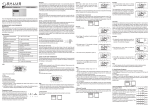
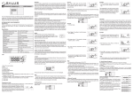
iT600 VS05 Installer - User Manual 005_Layout 1 08.12.2014 13:32 Strona 1
Dial Thermostat
Models: VS05
I N S TA L L E R / U S E R M A N U A L
iT600 VS05 Installer - User Manual 005_Layout 1 08.12.2014 13:32 Strona 2
Contents
Contents
Introduction.
Product Compliance.
Safety information.
Mounting position and
installation.
System grouping and
communication.
User interface.
LED indication.
Icons used in this manual:
Safety
For latest PDF installation
guide please go to
www.salus-controls.com
Important info
Your benefit
Box Contents
1 x Installer / User manual
02 VS05 Installer Manual
Fixing screws
VS05
iT600 VS05 Installer - User Manual 005_Layout 1 08.12.2014 13:32 Strona 3
Product Compliance & Safety Information
INTRODUCTION
Thank you for purchasing the SALUS room
thermostat VS05. The VS05 is a 230V dial
thermostat which offers simple temperature
control of your heating system.
SALUS recommends that you use your VS05
with the SALUS KL10 wiring centre and VS10
digital room thermostat. The VS10 can be used
as a group control thermostat to control groups
of VS05’s. Please see pages 6 and 7.
Product Compliance
This product is CE compliant and meets the
following EC Directives Electro-Magnetic
Compatibility directive 2004/108/EC
Low voltage Directive 2006/95/EC
Safety Information
Use in accordance with the regulations
The SALUS VS05 is to be used for room
control of hot water heating systems
inside the house.
Installation
This product must be fitted by a competent
person, and installation must comply with the
guidance, standards and regulations applicable
to the city, country or state where the product
is installed. Failure to comply with the
requirements of the relevant guidance,
standards and regulations could lead to injury,
death or prosecution.
Always isolate the AC mains supply
before installing or working on any components
that require 230V AC 50Hz supply.
We hope you enjoy this product...
VS05 Installer Manual 03
iT600 VS05 Installer - User Manual 005_Layout 1 08.12.2014 13:32 Strona 4
Product Compliance & Safety Information
Sources of danger
The thermostat must be disconnected from
mains supply before removing the cover.
230V AC
Installer parameter settings
The SALUS VS05 is equipped
with installer parameters. See page 13.
For the installer
Please enter any parameter
changes in the installer notes section.
Emergency
Switch off the voltage to the individual
thermostat wiring centre or complete system.
04 VS05 Installer Manual
iT600 VS05 Installer - User Manual 005_Layout 1 08.12.2014 13:32 Strona 5
Installation – Thermostat Mounting
Mounting position and installation
To ensure trouble free operation and efficient control, the unit is best positioned in
a draft free area and at 130cm from the floor. Do not position the thermostat near
any heat source, behind curtains, direct sunlight or an area of high humidity.
Not to be positioned on an exterior wall.
VS05 Installer Manual 05
iT600 VS05 Installer - User Manual 005_Layout 1 08.12.2014 13:32 Strona 6
System Overview Grouping and Communication
Power and Switching Cable - used to
power thermostats and drive output.
Grouping and Communication cable.
While the thermostats can function as standalone,
installing this optional inexpensive communication cable
allows the thermostats to communicate with the SALUS
VS10 configured as a group control thermostat and used
with the SALUS KL10 WC (both sold separately).
The VS05 will follow instructions from the VS10 bringing
central control of features such as Time Control, Holiday &
Party functions as well as Frost Control. The VS05 can leave
or re-enter group control at the slide of a switch.
06 VS05 Installer Manual
VS10 Group Control Thermostat
(sold separately )
iT600 VS05 Installer - User Manual 005_Layout 1 08.12.2014 13:32 Strona 7
System Overview Grouping and Communication
The maximum number of groups per KL10 wiring centre is two. The group selection
communication cable must correspond to the group terminals on the KL10 WC.
Please refer to note 5 and the KL10 installation guide.
Group 1 – For Example Down stairs
Group 2 – For Example upstairs
SALUS KL10 Wiring Centre
VS05 Installer Manual 07
iT600 VS05 Installer - User Manual 005_Layout 1 08.12.2014 13:32 Strona 8
Installation – Thermostat Mounting
1
2
Gently remove front housing.
3
08 VS05 Installer Manual
Wall Mounting
For wall mounting, mark and mount
the rear case to the wall. The VS05 is
suitable for wall boxes with a centre
hole distance of:
60mm
iT600 VS05 Installer - User Manual 005_Layout 1 08.12.2014 13:32 Strona 9
Installation – Terminal Connections
Understanding your terminal connections
1
Rear of VS05
2
3
3
2
1
Power Terminals 230 Vac
Used for supplying power to the
unit and switched output.
Sensor Terminals
Can be used for external Air or
Floor sensor.
Communication Terms 12VDC
Two wire twisted pair
can be used for grouping
functions between VS10 and VS05.
Also required for Heat/Cool
changeover.
VS05 Installer Manual 09
iT600 VS05 Installer - User Manual 005_Layout 1 08.12.2014 13:32 Strona 10
Installation – Thermostat Connections
Optional
communication
connection 12VDC
While the VS05 can function on
its own, installing this optional,
inexpensive communication
cable allows the VS05 to
communicate with the SALUS
VS10 (sold separately).
For more detail refer to note 5 on the wiring centre installation guide.
10 VS05 Installer Manual
iT600 VS05 Installer - User Manual 005_Layout 1 08.12.2014 13:32 Strona 11
Installation – Terminal Connections
Check that the wiring is completed for:
1
Power Terminals
2
Sensor Terminals (if applicable)
3
Communication Terminals (optional but recommended)
You are ready to secure the rear housing to the wall box
Please use the screws provided.
Ensure the orientation arrow
is pointing upwards.
VS05 Installer Manual 11
iT600 VS05 Installer - User Manual 005_Layout 1 08.12.2014 13:32 Strona 12
Installation
3
2
1
4
1 2 If any parameter settings need
to be changed please refer to next page.
12 VS05 Installer Manual
Fit the front housing to the rear
housing as shown above.
iT600 VS05 Installer - User Manual 005_Layout 1 08.12.2014 13:32 Strona 13
Installation – parameter setting
1
FUNCTION
External sensor (optional)
If you are fitting an external sensor for air/floor
sensing please select temp here. It can be set
from 0-45ºC and is preset at 27ºC. Please note
the dip switches 2 need to be set for the
correct external sensor type, see below.
2
DESCRIPTION
DEFAULT
Valve Exercising
If the installer setting is to enable the valve exercising the
dial thermostat will additionally send 5 minute pulse on
actuator once a week.
ENABLE
PWM
PWM output to drive actuator open/close.
ON
External sensor
type
Actuator type
Air or floor.
AIR
Normally Closed or Normally Open.
NC
Reduced temp
offset / Night
setback
0, 4, 6 or 8 (only when used with VS10 and KL10).
4ºC
VS05 Installer Manual 13
iT600 VS05 Installer - User Manual 005_Layout 1 08.12.2014 13:32 Strona 14
User Interface
LED Indication
Temperature Adjustment 5-30 oC
The VS05 is no longer a member of the group and will
ignore commands from the VS10 group control thermostat.
Mode
Selection
The VS05 is a group member and will follow commands
from the VS10 group control thermostat.
The VS10 is switched off, frost protection of 5ºC is active.
14 VS05 Installer Manual
iT600 VS05 Installer - User Manual 005_Layout 1 08.12.2014 13:32 Strona 15
LED Indication - Group Member
Slide switch must be in
position to follow group control thermostat VS10, see page 14.
RED LED indicates that power is going to the
thermostat in normal operation. The top LED
will illuminate when room temperature falls
below your required temperature.
Green LED means that the thermostat
is calling for heat. The group control
thermostat will be in one of the
following modes:
VS10 group control
thermostat display
1.
2.
3.
For more details on VS10
please refer to VS10 manual
If you do not want a VS05 to follow the group control thermostat VS10
please select
or
see previous page.
VS05 Installer Manual 15
iT600 VS05 Installer - User Manual 005_Layout 1 08.12.2014 13:32 Strona 16
LED Indication - Group Member
Slide switch must be in
position to follow group control thermostat VS10, see page 14.
To reduce annoyance factor, no LED is shown
when the group control thermostat is in
reduced temperature/night setback mode.
See below.
To adjust reduced temperature
offset please refer to page 13.
VS10 group control
thermostat display
Amber LED means that the
thermostat is calling for heat in
reduced/night setback mode.
The group control thermostat will
be in one of the following modes:
1.
2.
For more details on VS10
please refer to VS10 manual
If you do not want a VS05 to follow the group control thermostat VS10
please select
or
see page 14.
16 VS05 Installer Manual
iT600 VS05 Installer - User Manual 005_Layout 1 08.12.2014 13:32 Strona 17
LED Indication - Group Member
Slide switch must be in
position to follow group control thermostat VS10, see page 14.
Blue LED indicates the thermostat is in
frost protection mode. Frost protection
temperature is fixed at 5ºC.
Green LED means that the
temperature has fallen below the
frost protection level the thermostat
is calling for heat. The group control
thermostat will be in one of the
following modes:
VS10 group control
thermostat display
1.
2.
For more details on VS10
please refer to VS10 manual
If you do not want a VS05 to follow the group control thermostat VS10
please select
or
see page 14.
VS05 Installer Manual 17
iT600 VS05 Installer - User Manual 005_Layout 1 08.12.2014 13:32 Strona 18
LED Indication - Manual mode
To enter manual mode, slide the switch to the
position. The thermostat will not follow the group
control thermostat VS10 and will no longer be part of the group. The VS05 will work as a stand alone thermostat.
RED Led indicates that power is
going to the unit in normal
operation. The top LED will
illuminate when room
temperature falls below your
required temp.
Green LED means that
the unit is calling for heat.
To return the VS05 to the group (if applicable) move the slide switch to
18 VS05 Installer Manual
iT600 VS05 Installer - User Manual 005_Layout 1 08.12.2014 13:32 Strona 19
LED Indication -Permanent Frost Mode
To enter manual mode, slide the switch to the
position. The thermostat will not follow the group control
thermostat VS10 and will no longer be part of the group. The VS05 will be in permanent frost protection.
Blue LED indicates the
thermostat is in frost protection
mode. Frost protection
temperature is fixed at 5ºC.
Green LED indicates the
temperature has fallen below the
frost protection level and the
thermostat is calling for heat.
To return the VS05 to the group (if applicable) move the slide switch to
VS05 Installer Manual 19
iT600 VS05 Installer - User Manual 005_Layout 1 08.12.2014 13:32 Strona 20
Technical Detail
MODEL
TYPE
TEMPERATURE
Scale
Tolerance
Set Temperature range
Frost Protection
CONTROL
ENVIRONMENT RATINGS
Operating Temperature
Storage Temperature
Operating Humidity (non condensed)
POWER SOURCE
CONTROL SWITCH AND RATING
Loading
Input
AGENCY APPROVED
20 VS05 Installer Manual
VS05
Wired dial thermostat designed for 230V AC
heating/cooling applications
Celsius
0.5 ºC
5-30 ºC
5ºC
ON-OFF control / PWM control
0ºC to +50 ºC
-20ºC to +60 ºC
5-95 %RH
230Vac 50Hz
Maximum 3A at SL terminal
Comm Connection 12VDC
CE
iT600 VS05 Installer - User Manual 005_Layout 1 08.12.2014 13:32 Strona 21
Installer Notes
VS05 Installer Manual 21
iT600 VS05 Installer - User Manual 005_Layout 1 08.12.2014 13:32 Strona 22
Installer Notes
22 VS05 Installer Manual
iT600 VS05 Installer - User Manual 005_Layout 1 08.12.2014 13:32 Strona 23
Warranty
SALUS Controls warrants that this product will be free from any defect in materials or workmanship,
and shall perform in accordance with its specification, for a period of five years from the date of
installation. SALUS Controls sole liability for breach of this warranty will be (at its option) to repair or
replace the defective product.
Customer Name: .............................................................................................................................
Customer Address: ..........................................................................................................................
............................................................................... Post Code: ........................................................
Tel No: ........................................................ Email: .........................................................................
Engineers Company: .......................................................................................................................
Tel No: ......................................................... Email: ........................................................................
Instalation Date: ..............................................................................................................................
Engineers Name: ............................................................................................................................
Engineers Signature: .......................................................................................................................
VS05 Installer Manual 23
iT600 VS05 Installer - User Manual 005_Layout 1 08.12.2014 13:32 Strona 24
SALUS Controls plc
SALUS House
Dodworth Business Park South,
Whinby Road,
Dodworth, Barnsley S75 3SP, UK.
SALES:
T: +44 (0) 1226 323961
E: [email protected]
TECHNICAL:
T: +44 (0) 1226 323961
E: [email protected]
www.salus-controls.com
SALUS Controls is a member of the Computime Group
Maintaining a policy of continuous product development SALUS Controls plc reserve the right to
change specification, design and materials of products listed in this brochure without prior notice.
Issue Date: April 2014
00086/2
For PDF Installation guide please go to www.salus-controls.com