1
EMBEDDED
PLC BL2500 User’s Manual
Hardware Reference
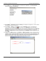
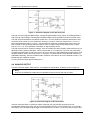
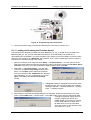
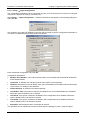
Figure 9: BL2500 Multidrop Network
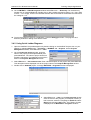
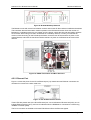
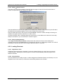
The BL2500 comes with a 220 W termination resistor and two 681 W bias resistors installed and enabled.
The load these bias and termination resistors present to the RS-485 transceiver limits the number of
BL2500s in a multidrop network to one master and nine slaves, unless the bias and termination resistors
are removed. When using more than 10 BL2500s in a multidrop network, or when you need the full
common-mode immunity per the RS-485 specification, leave the 681 W bias resistors in place on the
master BL2500, and leave the 220 W termination resistors in place on the BL2500 at each end of the
network.
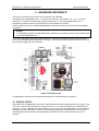
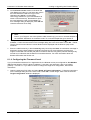
Figure 10: RS485 Termination and Bias Resistors
4.5.2 Ethernet Port
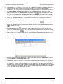
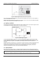
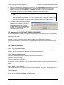
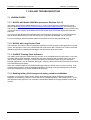
Figure 11 shows the pinout for the RJ-45 Ethernet port (J4). Note that some Ethernet connectors are
numbered in reverse to the order used here.
Figure 11: RJ-45 Ethernet Port Pinout
Three LEDs are placed next to the RJ-45 Ethernet jack, one to indicate an Ethernet link (LNK), one to
indicate Ethernet activity (ACT), and one to indicate when the RCM3200 is connected to a functioning
100Base-T network (SPD).
The RJ-45 connector is shielded to minimize EMI effects to/from the Ethernet signals.
OEM Technology Solutions
Page 39