1
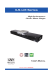
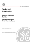
LTTC-GE
EN
Linearr time code
c
generattor
(SM
MPTE time
t coode geeneratoor)
| Manuaal |
Version 1.00
6/16/2014
Table of contents
1. GENERAL DESCRIPTION
1 2. FRONT PANEL AND CONNECTIONS
2 3. POWERING THE LTC-GEN
4 4. PRIMARY DISPLAY MODE
4 5. HOTKEYS
5 6. MAIN MENU
6 6.1. FRAME RATE
6.2. PARITY
6.3. SET TIME CODE
6.4. SET RTC (REAL TIME CLOCK)
6.5. MISC. SETTINGS
6.5.1 MENU COLOR
6.5.2 INT TC COLOR
6.5.3 EXT TC COLOR
6.5.4 BATTERY
7. TECHNICAL SPECIFICATIONS
6/16/2014
7 7 7 7 7 7 7 7 7 8 1. General description
The Marenius LTC-GEN is a linear time code generator encoding SMPTE time code into an
audio signal. The device is able to read and jam to an external time code signal. The device is
supporting cross-jamming between different frame rates.
An extremely wide viewing-angle and very clear OLED display is used for time code display,
menus and information.
LTC-GEN can be powered from standard LR03 (AAA type) batteries and/or an external 5-15V
power supply. A supercap is used instead of a traditional backup battery for real time clock and
LTC, meaning no internal battery needs to be replaced. A LED is used to indicate operation
when the OLED is turned off. A very accurate 0.5ppm crystal oscillator is used to ensure time
code accuracy for at least 8 hours. The crystal is voltage tuned when the device is shipped from
the factory.
The LTC-GEN is housed in a heavy duty aluminum cabinet.
Package includes:
1x LTC-Generator
1x 9VDC adaptor
1x BNC-BNC cable
1x BNC-RCA adapter
4x AAA batteries
6/16/2014 LTC-GEN User Manual v.1.00
1
2. Front panel and connections
1.
OLED Display
Displays operation information, settings and menus.
2.
UP / HOLD button
When the device is in menu mode this button is UP button. When the device is in default
mode the button will hold the time code both in the display and on the output, however the
internal counter is still counting. When the button is released the time code will catch up to
the internal counter.
3.
MENU / ENTER button
Pressing the MENU / ENTER button will enter the main menu. When the device is in menu
mode the button is used to confirm a selection.
4.
DOWN / JAM button
When the device is in menu mode this button is DOWN button. When the device is in
default mode the button will JAM the device to the external time code if a valid time code is
presented. The button must be hold down until “JAM” is flashing on the display.
5.
1PPS LED
The LED will flash each second when the device is operating (exception: HOLD mode).
6/16/2014 LTC-GEN User Manual v.1.00
2
6.
Power switch
The switch is used to power on or off the device.
7.
Power input
The power input accepts 5V to 15V DC.
Note: voltage levels above 15V will damage the unit.
8.
Code output
This is the main time code output. The output level is 2Vpp (unloaded).
8.
Code input
The connector is used to read an external time code from a third party device. The LTCGEN is able to synchronize to the external time code independent of the frame rate.
6/16/2014 LTC-GEN User Manual v.1.00
3
3. Powering the LTC-GEN
The LTC-GEN can be powered from an external power supply or four standard LR03 (AAA
type) batteries. Both NiMH and alkaline batteries can be used.
The batteries shall be placed in the battery holder as the label on the battery cover describes.
The battery chemistry shall be set in the main menu to allow the unit to display the correct
battery level.
The MM-4240 can be powered from an external power supply of 5V-15V; the external power
supply can be a mains adapter, batteries or any power supply that is able to delivery at least
0.5A of current. Even if the LTC-GEN doesn’t draw 0.5A the power supply must be able to
handle load transients.
The internal batteries are disconnected from the unit when an external power supply is
connected to the unit. Therefore it is very important that the voltage level of the external power
supply doesn’t drop below 5V.
4. Primary display mode
When the LTC-GEN is powered up the default display mode is entered. The unit displays
internal time code, external time code, real time clock and power information.
The image below shows the primary display mode.
6/16/2014 LTC-GEN User Manual v.1.00
4
1.
Internal time code
The line is displaying the internal time code, the time code displayed here is the time code
generated at the output.
2.
Internal time code format
The format of the internal time code (24 FPS, 25FPS, 30FPS or 30FPS DF)
3.
External time code
The line is displaying the external time code, if no time code is presented on the input the
device is showing --:--:--:--.
4.
External time code format
The format of the external time code (24 FPS, 25FPS, 30FPS or 30FPS DF). The device is
using the drop frame bit to detect drop frame, if the third party generator isn’t supporting
drop frame bit the LTC-GEN isn’t able to display this information.
5.
RTC
Real time clock. The clock can be set via the menu.
6.
External power
The power symbol is lit when an external power source is attached to the unit.
7.
Battery level
Displays current internal battery level. The symbol is filled with green or red depending on
the current level. If the symbol is flashing, replace the batteries as soon as possible. The
LTC-GEN will only run for about 15 minutes when the battery symbol is flashing.
Note: For a true display of the battery level, the battery chemistry must be set.
8.
JAM/HOLD field
If the device is jamming or holding the time code this field is used otherwise the field is
blank.
5. HOTKEYS
The LTC-GEN has two hotkey functions, “+1h” and “SET TO RTC”. Holding down the UP button
in default mode will enable the hotkey function. When holding down the UP button press either
MENU button or DOWN button to increase one hour or synchronize the internal time code to
the real time clock.
UP button + MENU button = Increase one hour.
UP button + DOWN button = Synchronize the internal time code to the real time clock.
6/16/2014 LTC-GEN User Manual v.1.00
5
6. Main menu
Secondary functions are accessible through the main menu. To enter the main menu press the
MENU button. To navigate through the menu use the MENU UP, DOWN and CENTER buttons.
The main menu structure is shown in the illustration below. The menu will automatically return
one step every 15 second until the general screen has been reached.
6/16/2014 LTC-GEN User Manual v.1.00
6
6.1. Frame rate
This frame rate option set the main frame rate of the time code generation. The avalible options
are:
• 24 FPS
• 25 FPS
• 30 FPS
• 30 FPS with drop frame
6.2. Parity
The user is able to turn on or off the parity bit defined in the SMPTE 12M specification. This
may be useful if the device connected to the LTC-GEN doesn’t support parity. If a third party
connected device doesn’t support parity the reader may flicker if the parity bit is enabled.
6.3. Set time code
If the user want to change the outgoing time code this menu option is used. The ENTER button
is used to step forward in the fields. The UP and DOWN button is used to change hours,
minutes and seconds. The new time code is activated on the last ENTER button click
(confirming seconds).
6.4. Set RTC (real time clock)
The menu option is used to set the real time clock. See 5.3 Set time code, for procedure.
6.5. MISC. SETTINGS
The general setup menu handles various settings of the LTC-GEN
6.5.1 MENU COLOR
The user is able to change the colors used in the menu and the colors used in the channel
information rows. The available colors are:
•
•
•
•
•
•
•
PURPLE
RED
GREEN
BLUE
DARK RED
YELLOW
PINK
6.5.2 INT TC COLOR
See 5.5.1 MENU COLOR.
6.5.3 EXT TC COLOR
See 5.5.1 MENU COLOR.
6.5.4 BATTERY
The battery chemistry must be set to the battery chemistry used for a correct battery level
meter. The choices are
• Alkaline
• NiMH
Other batteries may be used as long as the voltage stays between 4V and 10V; however the
battery level indicator will be incorrect.
6/16/2014 LTC-GEN User Manual v.1.00
7
7. Technical specifications
Power supply
External supply voltage ............................................................................... 5-15 VDC
Power consumption (Typ)............................................................................ 0.2W
Internal battery voltage ................................................................................ 4-10VDC
Time code output
Output level.................................................................................................. 2Vpp (Unloaded)
Output impedance ....................................................................................... 470Ω
Crystal oscillator precision ........................................................................... 0.5ppm
Time code input
Minimum input level ..................................................................................... 0.5Vpp
Maximum input level .................................................................................... 5Vpp
Input impedance .......................................................................................... 100kΩ
Dimensions and weight
Size (H x W x D) .......................................................................................... 3.4 x 8.5 x 9.7 cm
Weight (without batteries) ............................................................................ ~350 grams
6/16/2014 LTC-GEN User Manual v.1.00
8