Download Diesel Generator Operation and Maintenance Manual

Transcript
Diesel Generator
Operation and Maintenance Manual
HYUNDAI ENGINE Series
Safety and Warning Before operation and maintenance for the generator sets, please read carefully about this manual and make sure a good understanding of this operation manual and other documents which attached with the engine. Correct installation of the generator set is the precondition of normal operation. Qualified spare parts shall be used for maintenance to ensure good running condition and long life expectancy of the generator sets. The generator set shall be operated only by the staffs who have received training on the operation and the repair shall be made by the authorized staffs. Operator and maintenance staff shall be clear about safety and preventive actions and operation maintenance procedure. The generator sets can only be started under safety conditions. Please do not start the generator sets when any abnormal condition has been found so that to avoid accidents. When clean, maintain and repair the generator sets, please shut down the generator set and cut off the connection of negative polar of the battery or dismantle battery connecting cable, and place warning label at the relative place so that to avoid accident. The exhaust air discharged from engine is harmful for people’s health. All of the generator sets installed indoors shall discharge the exhaust gas to outside doors. During the period of generator set running, the exhaust pipe and silencer will generate high temperature. Therefore when the generator set is installed, these parts need to be covered with insulation materials and be kept far away from inflammable materials. Please ensure good ventilation and organized environment for the generator set’s installation room. Please do not place inflammable materials and explosives (liquid) near the engine. Smoking, spark over, and other fire lighting behaviors are not allowed in the area which is close to the battery and fuel because the mixture of volatilization from fuel and hydrogen generated by battery charging process will cause explosion when it meets sparkle or naked flame. The generator set installation room shall be facilitated with BC and ABC fire extinguisher, and operators shall be familiar with the knowledge on how to use it. When fan protection cover or other protection cover has been detached, please do not try to start the generator set; and when the generator set has to be started, please don’t put your hand in the area where the protection cover is missing or make repair around these areas. Please keep your palm, arm, long hair, jewelry and loose clothes far away from belt pulley, belt and other power transmission parts. When working in the generator set installation room, please ware working clothes, gloves and hat. After the generator set being started, please don’t try to open the cover of the radiator before the anti‐freeze fully cooled down, so that to avoid steam (hot water) burst forth to hurt people. Please don’t swallow or let your skin contact with the harmful materials such as fuel, anti‐freeze, lubricant and electrolyte. When you skin is spattered with these kinds of liquids, please use plenty of water to rinse. Long time stay in high noise level environment will cause harm to your hearing. If you have to work around the generator set frequently, you’d better ware the device to protect your ear. When the generator set need to make cable connections to output power, the operation shall conform to the condition, specification, standard related to power distribution. Qualified cable shall be used to make power distribution. When the installation of generator set involves with welding, please do not connect to the ground circuit or make grounding through generator set (engine) so that to avoid the big current generated from welding operation hurt the electric appliance, bearing and bearing bush etc. inside of the generator set. Please ensure the safety of generator set and reliable grounding. Safety labels information TRANSPORT WARNING ! Never lift the generating set by attaching to the engine or alternator lifting lugs, instead use the lifting points on the base frame or canopy. ! Ensure that the lifting rigging and supporting structure is in good condition and has a capacity suitable for the load. ! Keep all personnel away from the generating set when it is suspended. MECHANICAL WARNING ! Do not attempt to operate the generating set with the safety guards removed. While the generating set is running do not attempt to reach under or around the guards to do maintenance or for any other reason. ! Keep hands, arms, long hair, loose clothing and jewelers away from pulleys, belts and other moving parts. SAFEGUARD WARNING ! Generating sets that are not equipped with sound attenuating enclosures can produce noise levels in excess of 105 dB (A). Prolonged exposure to noise levels above 85 dB (A) is hazardous to hearing. ! Wear protective clothing including gloves and hat when working around the generating set. ! If equipped keep access doors on enclosures closed and locked when not required to be open. ! Avoid contact with hot oil, hot coolant, hot exhaust gases, hot surfaces and sharp edges and corners. CHEMICAL WARNING !Ensure that the generating set room is properly ventilated. !Keep the room, the floor and the generating set clean. When spills of fuel, oil, battery electrolyte or coolant occur, they should be cleaned up immediately. ! Never store flammable liquids near the engine. !Do not smoke or allow sparks, flames or other sources of ignition around fuel or batteries. Fuel vapors are explosive. Hydrogen gas generated by charging batteries is also explosive. ! Never store flammable liquids near the engine. !Do not smoke or allow sparks, flames or other sources of ignition around fuel or batteries. Fuel vapors are explosive. Hydrogen gas generated by charging batteries is also explosive. ELECTRICAL WARNING ! The generating set should be shutdown with the battery negative (‐) terminal disconnected prior to attempting to connect or disconnect load connections. ! Do not attempt to connect or disconnect load connections while standing in water or on wet or soggy ground. ! Make sure connect generator set to earth. ! Replace the generating set terminal box cover as soon as connection or disconnection of the load cables is complete. Do not operate the generating set without the cover securely in place. ! Connect the generating set only to loads and/ or electrical systems that are compatible with its electrical characteristics and that are within its rated capacity. ! Keep all electrical equipment clean and dry. Replace any wiring where the insulation is cracked, cut, abraded or otherwise degraded. Replace terminals that are worn, discolored or corroded. Keep terminals clean and tight. ! Do not touch electrically energized parts of the generating set and/or interconnecting cables or conductors with any part of the body or with any non insulated conductive object. Table of Contents
1 General Introduction
2.11 Power distribution system………………………11
1.1 Brief Introduction……………………………………1
3 Operation
1.2 Generator Set Main Parts Specifications…………1
3.1 Inspect Before Operation ………………………12
1.4 Alternator ……………………………………………1
3.2 Generator set’s running …………………………12
1.3 Diesel Engine ……………………………………… 1
3.3 After Running ……………………………………13
1.4 Alternator …………………… …………………… 1
3.4 Record for running ………………………………13
1.5 Cooling System ……………………………………2
3.5 Matters need attention …………………………13
1.6 Electrical System …………………………………2
3.6 Operation for control system ……………………14
1.7 Coupling ……………………………………………2
3.7 ATS control panel ………………………………16
1.8 Fuel Tank and Base Frame ………………………2
4 Maintenance
1.9 Control Panel ………………………………………2
4.1 General outline……………………………………18
1.10 Optional for Canopy Generator Set ……………2
4.2 Engine ……………………………………………18
1.11 Others ……………………………………………3
4.3 Alternator …………………………………………19
2 Installation
4.4 Control panel ……………………………………19
2.1 General Outline ……………………………………4
4.5 Start battery ………………………………………19
2.2 Transportation ……………………………………4
4.6 Maintenance record ……………………………19
2.3 Design for Foundation ……………………………4
5 Check for Malfunction
2.4 Design for Generator Set Working Room ………4
5.1 General outline……………………………………20
2.5 Installation of Generator Set………………………5
5.2 Malfunction checklist ……………………………21
2.6 Cooling system ……………………………………7
2.7 Lubricant system …………………………………8
2.8 Fuel system…………………………………………8
2.9 Battery ……………………………………………10
2.10 Electrical Connection……………………………11
APPENDIX
User manual
1 General Introduction 1.1 Brief Introduction HYUNDAI series diesel engine generator sets is the core products of HYUNDAI Power Equipment Manufacturing Co.,Ltd. Thanks to their good performance, the generator sets are widely used in the fields of construction, communication, banking business, mining, leasing industry and other special sites. As what you are expecting, HYUNDAI generator sets endeavor to meet your needs for the concept of individual design through the excellent features of more safe, more reliable and more clean. The generator sets provided by HYUNDAI Power is reliable and professional. The advantage of low noise level, energy conservation, and stable performance has made a credible assurance for many enterprises. Our generator sets supply the following power service: Continuous service Used as main power supply to generate electricity for several purposes: motion force, lighting, heating etc. The generator sets can continue running and allow 10% over load for 1 hour per 12 hours under variable load, which is used for remote area. Standby service Used as standby power supply to provide continue electric power for non‐invariable loads. The generator set is suitable for the area where must ensure continue power supply, such as hospitals, industrial facilities, airports etc. Keep the generator set standby state at any time and start to run when the mains supply is abnormal. Emergency service Used as auxiliary power supply to solve energy interruptions that may cause serious problems to people, physical and /or financial damage or to face consumption peaks. The generator set can start in short order to provide steady electric power for the loads when the mains supply happen abnormity, and switch to stop after the mains supply becomes normal. Generally the generator set continues working for several hours. NO NAME 1
CONTROL PANEL
2
BUSBAR PANEL
3
LIFTING LUG
4
BASEFRAME FUEL TANK
5
ENGINE
6
BATTERY
7
RADIATOR
8
ALTERNATOR
9
FUEL DRAIN OUTLET
10
FUEL LEVEL SENSOR\
11
ABSORBER
1.2 Generator Set Main Parts Specifications 1.3 Diesel Engine According to different output power of the generator sets, and combine with the advantage of each model of diesel engine in a specific range of power output, HYUNDAI Power chooses the engines with first class performance and high reliability. And furthermore, HYUNDAI Power pay special attention to the 1
User manual
technical advantage of engines in the aspects of reducing exhaust gas, decrease fuel consumption rate and good noise level control. fitted if they were specified. 1.4 Alternator Engine and alternator are firmly joined by a coupling cone that guarantees the proper assembly coaxiality Single‐support machines are also used a special flexible disk is used in place of a flexible coupling. 1.7 Coupling All of the alternators chosen by HYUNDAI Power are single bearing self‐excitation brushless alternators with the attributes of international top brand. By 1.8 Fuel Tank and Base Frame citing Stamford alternator as an example, we can illustrate the features of our alternators as follows: The engine and alternator are coupled together and ◆Four polar brushless self‐excitation, single bearing, mounted on a heavy duty steel base frame. This base insulation class is H and protection level is IP22. frame includes a fuel tank with capacity of ◆Stators are wound to 2/3 pitch, which can effectively approximately 8 hours operation under variable loads. eliminates triple and curbs waveform deformation of The tank is complete with filling cap and fuel level output voltage. When in parallel with the mains or gauge and is connected by flexible joints to the intake other generator sets, this type of winding can piping and to the overflow piping containing fuel effectively avoid excessive neutral currents and from the injector drain. Big capacity generator's fuel reduces inductive heat. tank is separate from generator set. ◆Before being assembled, rotors need to pass dynamic 1.9 Control Panel balance testing. The improved damper reduces voltage deviation and heat under unstable load. All models of HYUNDAI Power generator sets use ◆The exciter rotor output is fed to the main rotor high grade control panel. The core of control panel is through a three phase full wave bridge rectifier, the an imported digital diesel engine control module, rectifier is protected by a surge suppressor against which has been facilitated with more complex surges caused by short circuit or out‐of‐phase functions such as further monitors, demonstration, paralleling. people‐module dialogue, distance communication ◆ Automatic voltage regulator has the feature of and protection etc. automatic load curtailment which is used to protect HYUNDAI Power generator set control panel use the engine, and make it possible to add full load to steel plate structure, which ensures security and the alternator at one time. Steady state voltage reliability, and the surface of it has been treated with adjusting rate can reach ±1% (under certain static powder painting. The outside appearance is requirements, steady state voltage adjusting rate can beautiful. Special lock has been used to fix it. It has meet ±0.5%). If PMG system is chosen, the motor been designed for easy maintenance. will have high starting capacity and the ability of interference rejection for the deformed voltage waveform fed by the main stator generated by 1.10 Optional for Canopy Generator Set non‐linear load(such as silicon control DC electric motor, UPS etc). 1.10.1 External antifreeze adding hole ◆ Telephone influence factor TIF<50, telephone Our generator sets has been facilitated with external harmonic wave factor THF<2%,the brushless style antifreeze filling hole. When user intends to add and high quality AVR ensures low interference with antifreeze, He only needs to open the antifreeze Radio. filling hole on the roof of canopy and the radiator’s 1.5 Cooling System pressure valve cap to directly add antifreeze to the hole, and easily watch the anti‐freeze level. The engine cooling system is water cooled. The water cooled system is comprised of a radiator a pusher fan and thermostat. The alternator has its own internal fan to cool the alternator components. 1.6 Electrical System The engine electrical system is 12 volt or 24 volts DC, negative ground/earth. This system includes an electric engine starter, a battery and a battery charging alternator. For DC 12 volts electrical system one battery is given. For 24 volt system two lead‐acid batteries are given. Other types of batteries may be 2
User mannual
allso it can prevent the generator sets from be
eing daamaged by c
cold winter w
weather! 1.10.2 Lubricant dischaarge hole wh
hich directlyy connect to outside Our generrator sets have been facilitated with lubricant diischarge valvve which co
onnect direcctly to outside. Th
his lubricantt discharge valve is an
nother humanized design feature of HYU
UNDAI Pow
wer. It offers morre convenien
nt operation for the users. When you want to diischarge surrplus lubricaant or change it, you can easily make itt by opening the lubricant disscharge ball valve. 1..11 Others Ex
xcept for ab
bove mention
ned compon
nents, the die
esel ge
enerator sett has other main compo
onents such as: baattery for start motor, battery cable, silencer, co
orrugated pipe, p
exhau
ust elbow, high‐efficie
ency viibration redu
uction unit, aand other allternative paarts, su
uch as base frame type
e fuel tank, daily fuel taank, caanopy, the lu
ubricant used
d by the engine at first time, an
nti‐freeze an
nd other partts specially re
equested by the cu
ustomer etcc. For the
e specific accessory paarts, please refer to generaator set paacking list and co
ontract. 1.10.3 Imprroved design
n for easy trransportatio
on Our canopyy generator sets have been b
designe
ed for easy hoistin
ng and tran
nsportation. Standard caanopy generator set s is facilitaated with liffting hole on o the base frame. For the sm
mall power generator setts, we ned hoisting
g lug on the canopy roo
of and have design
forklift ope
ening in the
e base fram
me, which better b
serves the needs of customers who have statiionary power supp
plier but nee
ed to move the generato
or set frequently. 1.11 Pre‐heaater for gen
nerator set (Optional Spare S
Part) Our generattor set has b
been facilitate
ed with heatter for water jacke
et. The purpo
ose to install the pre‐heaater is to ensure th
hat the gene
erator set can
n be started under low temperature and some emerg
gency casess, and 3
User manual
◆Ensure foundation’s levelness and smoothness. ◆If possible, waste discharge sink can be sued so that the waste oil can be discharged in a timely manner. Cable channel for generator power output cable need to be reserved. ◆Normally, concrete foundation is reliable, simple and preferable. When pouring the concrete foundation, please make sure the surface of concrete is flat, and no scratch is allowed. Gradienter or similar instruments need to be used during installation of generator set and its exhaust system. The design of foundation can refer to following calculation formula: (below is the diagram for diesel generator set foundation) 1. Generator dimension length × width: L1×W1 2. Foundation dimension length × width: L2×W2 L2 =L1+400 (mm) W2 =W1+400 (mm) 3. B=2×M/ (L2×W2×D) B: Thickness of foundation M: Generator set weight L2: Length of foundation W2: Width of foundation D: Density of Concrete (refer to 2322kg/m3) (Foundation drawing Refer to APPENDIX A ) 2 Installation
2.1 General Outline Correct installation of generator set is the precondition which ensure the normal working status of the generator set. The working room for generator set shall be designed specifically to meet the expected functions and maintenance operations, and at the same time the design of generator set working room shall conform to local government’s laws and regulations on architecture, fire protection laws and other applicable regulations. 2.2 Transportation During the period of shipment, protection shall be made for the generator set. In addition, the generator set shall be tightly secured in the loading truck so that to avoid any vibration during shipment which will cause the generator set’s components loosen and even damaged. During the process of shipment of generator set, no people or other material is allowed to place above the generator set so that to avoid damage to generator set caused by weight. When loading or unloading the generator set to the truck, forklift or hoisting device shall be used to avoid the generator set become tilted or fell to the ground, which causes damage. Lifting holes have been designed on the common base frame of our generator sets. Some of the specifically designed generator sets has been facilitated with lifting holes on the roof and forklift openings on the base frame etc. Users can transport the generator set according to the guidance specified on the specific labels sticked on the generator set. Please do not use the lifting lugs on the engine or on the alternator to hoist the whole generator set. 2.4 Design for Generator Set Working Room The installation of generator set shall be designed, so that to meet the demand of planned operation and maintenance. The complete installation shall conform to local architecture laws, fire protection laws and other applicable regulations. Except the above matters, there are other matters needs your attention as follows: ◆Ensure diesel engine generator set working room is furnished with rainproof, sunscreen, and windproof. ◆Ensure diesel engine generator set working room has good ventilation and good exhaust system, and the area for ventilation is sufficient, and at the same time use pipes to let out the hot air generated from the radiator and prevent the hot air from returning. ◆Ensure the waste gas generated during generator set running period can be discharged to outside timely, and try your best to reduce the adverse effect caused to environment. The silencer and exhaust pipe shall be supported by the roof, the supporter shall allow the exhaust pipe to expand. It is not permitted to install the exhaust system directly on the generator set. ◆ Enough space shall be reserved for the diesel generator set for convenience of cooling, operation and maintenance etc. Generally speaking, no foreign material is allowed to be placed within the area of 2.3 Design for Foundation The foundation which used to install and fix the diesel generator set is very important, it must conform to the following requirement: ◆Have enough hardness and stability, so that to avoid deformation, which will affect the concentricity of diesel engine and alternator and other accessory parts. ◆To support the weight of the whole generator set and to absorb the dynamic impact caused by unbalanced force and vibration during engine’s running period. ◆Generator set’s foundation is not allowed to connect to other architecture’s foundation. ◆ The width and depth of foundation shall meet requirement. 4
User manual
1~1.5 m of distance from the generator set and 1.5~2m above the generator set. ◆The generator set working room shall be furnished with fire extinguish hydrant which conform to the specified standard. ◆Emergency lighting facilities shall be installed in the generator set working room for the convenience of operation and maintenance. ◆No combustible and explosive materials are allowed to be placed in the generator set working room. Below is the layout for the open system generator set working room. Soft connection is needed to connect the parts of the generator set to outside. For example: corrugated vibration reduction pipe has been used to connect exhaust pipes, air exhaust path, fuel inlet pipe, fuel return pipe and busbar cable etc., all of these parts need to use soft connections. Only in this way we can reduce the adverse effect caused by the vibration of generator set to the minimum extent. 2.5.2 Ventilation When a generator set with a complete set of radiator assembly has been installed in the working room, the basic principle is to discharge the hot air in the working room to outside and let in the low temperature air from outside, and try you best to avoid the hot air come in from outside. The diagram in the right side demonstrates the ideal position of a generator set in the working room. The purpose of this arrangement is to get cold air from the lowest point as much as possible, and force them to pass through the radiator core, and then lead them out. (Foundation drawing Refer to APPENDIX B ) Note: Our company can make drawings and design installation dimensions for generator set working room according to customer’s special requirements. Below is the layout for the canopy system generator set working room. (Foundation drawing Refer to APPENDIX C )
Users can use metal plate or canvas to make a wind guide cover, the connection between wind guide cover and the radiator shall be soft connection, so that to cut off the transmission of vibration from the generator set, and also ensure the hot air exhaust to outside thoroughly. The effective circulation sectional area inside of the wind guide cover shall be bigger than 1.25 times of the front face area of the radiator core. And the wind guide cover shall be smooth, no sharp angle and camber so that to reduce the resistance to the wind. At the same time, the effective circulation sectional area in the air inlet opening shall also be bigger than 1.25 times of the front face area of the radiator core. When the users have installed mesh cover or shutters in the air inlet /outlet opening or there is too many cambers in the air inlet/outlet opening, the effective air circulation sectional area will be reduced and resistance will increase, and therefore, it’s necessary to further increase air circulation area. Note: Canopied generator set can work outdoor directly. If users wants to operate the generator set indoor, above diagram can be taken as reference. we can design the layout of generator set working room and installation dimension according to customer’s special requirements. 2.5 Installation of Generator Set 2.5.1 Locate the position of generator set Vibration reduction units have been installed on our generator sets (except a few generator sets don’t have this kind of facility). Users can take reference on the installation diagram, correctly install the generator set on a flat and hard foundation, use the expansion bolts to tightly fix the generator set to the concrete foundation through the installation holes on the base frame. When no special requirement is needed, we don’t suggest customers to install additional vibration reduction units. 5
User manual
and side stress. ◆ Reserve some space for hot shrinkage and cold expansion. ◆Reserve space for generator set vibration. ◆Reduce exhaust noise level. Overload of exhaust backpressure will cause following adverse effect: ◆Output power loss ◆Fuel efficiency reduce ◆Exhaust gas temperature rise Note: When more than one generator set are installed, try not to discharge all of the generator sets’ gas from one exhaust path. If no separated exhaust pipe is allowed, under the condition that the total backpressure will not exceed the generator sets’ total backpressure a moveable separate panel shall be installed inside of the branch exhaust pipe so that to prevent the gas from return. In the exhaust system, soft corrugated pipe shall be used to connect the exhaust pipe with the turbocharger, this pipe has three functions as follows: ◆Separate the diesel engine with vibration and the weight of exhaust pipe. ◆Compensate the heat expansion of exhaust pipe. If the diesel generator set is installed on the anti‐vibration base frame, the corrugated pipe can compensate sideway movement when engine start or stop. Note: 1. Serious damage will occur when rain or condensed water enter into engine’s exhaust system. Therefore, one water discharge opening shall be installed in the long exhaust pipe, the position of which shall be close to the generator set. 2. When the top of the exhaust pipe is above the architecture, lightening protection is needed (connect to the ground) Under normal conditions, the air volume generated from the radiator’s fan is enough to meet the requirement of the working room ventilation. The air inlet temperature of the engine shall be below 30 degree Celsius. If the air inlet temperature keep rising above 30 degree Celsius, the engine’s output power will be reduced, and therefore fresh air from outside shall be introduced into the generator set’s working room in a timely manner. If the generator set is furnished with a remote radiator, forced air circulation for the generator set working room is a must. The forced air circulation need two fans, one fan is responsible for air intake, another is air exhaust, which exhausts hot air to outside. When the engine is furnished with propelled fan, it is recommended that a separate pipe is needed to exhaust the gas which generated from the crankcase to outside. Otherwise the exhaust gas from the crankcase will accumulate on the radiator, which will cause the radiator stuck by dirty material, and as a result, the heat‐sinking capacity will be reduced. 2.5.3 Exhaust Our standard configuration diesel generator sets provide accessories such as industry heavy silencer, soft corrugated pipe and elbow etc. Users can design the exhaust system of generator set working room by themselves. When design and install the exhaust system, please consider the following aspects: ◆Ensure the total exhaust backpressure no higher than the maximum allowed value specified by the engine(usually generator set’s maximum exhaust backpressure is no more than 5Kpa) Fix the exhaust system to make sure the exhaust manifold and turbo‐charger are not subject to the vertical pressure 2.5.4 Noise reduction When diesel generator set is running, normally it will generate noise level of 90~110dB, and the more the load, the higher the noise level. In order to meet the noise level standards established by the local environmental protection bureau and to prevent the noise pollution caused to ambient environment, which will affect people’s normal life, to reduce noise level of diesel generator set is also 6
User manual
radiator, ensure the anti‐freeze will not freeze under low temperature. In the area when there is low possibility of freezing, the coolant can be a mixture of water and anti‐rust, according to the anti‐rust which recommended by the engine supplier and refer to its operation manual, mix the liquids in a separate container evenly and then add the mixture into the radiator. At the first time when anti‐rust is added, the generator set shall be kept running until it get to hot so that to achieve the best effect of anti‐corrosion. Engine’s coolant shall have three functions listed as below: ◆Provide enough heat transmission capacity ◆ Prevent all metal material and sealing material within the cooling system from corrosion(Cave corrosion) ◆Provide sufficient anti‐freeze capacity Warning: ! To choose the anti‐freeze which is recommended and approved by the qualified engine supplier is the critical point to ensure engine’s normal running. ! Do not mix the anti‐freeze and anti‐rust of any types, this will generate a large amount of bubble and reduce the coolant’s performance. ! If the anti‐freeze used in the generator set is of bad quality and not approved by the engine supplier, which cause the malfunction of the generator set (water leakage, contamination and etc.), this malfunction(s) does not belong to the scope of warranty. very important. Noise reduction engineering is a comprehensive and professional engineering. During the process when users try to design the scheme for noise reduction project, at the same time please fully consider the bottom limit of air inlet/outlet volume needed by engine’s normal running and the maximum allowed value for exhaust backpressure etc. Otherwise, the noise reduction project will seriously affect generator set’s output power, and make generator set’ s temperature rise, cause frequent malfunction of the generator set, and even it will shorten the life expectancy of generator set. Note: HYUNDAI Power can provide customers with overall sound proof generator set. 2.6 Cooling system Our standard configuration diesel generator sets are closed cycling water chilling units with fan and radiator installed. Closed water chilling engine drive the cooling pump to generate circulation power, which keep the anti‐freeze in the paths of cylinder body and cover continuous circulation and heat elimination. Engine’s cooling pump, radiator (or heat exchanger) forms a closed, pressure cycling and cooling system. The most common cooling system is cooling fan directly driven by radiator and engine, which can be replaced by heat exchanger, remote radiator or remote cooling tower etc. If the installation position of the remote cooling fan is relatively higher, transmission radiator is needed to prevent the damage of heat exchanger caused by too big internal pressure. Note: The dirty material stay in the radiator’s core will greatly affect radiator’s cooling capacity. And therefore it is necessary to clean the radiator often. 2.6.2 Change of coolant The effect of anti‐freeze and anti‐rust will decrease by the time period of service. And therefore periodically change of anti‐freeze is a must. The mixture of anti‐freeze shall be changed in every two years. The mixture of anti‐rust shall be changed at least one time every year. And if filter of the coolant is installed, at least this filter shall be changed in every half of year (please refer to the engine operation manual for the specific intervals of the changes required). When it is time to discharge the coolant, make sure the generator set has been shut down and the engine has been fully cooled down, then open the radiator’s liquid adding hole. After that open the discharge valve installed in the radiator and in the engine respectively to discharge the water. If the generator set is furnished with coolant filter, it shall be detached from the engine and be changed. 2.6.1 Coolant Cooling system shall use the coolant which can protect the engine from contamination and freezing. Coolant shall be a mixture of pure water and anti‐freeze or pure water and anti‐rust fluid. In this mixture, water PH value shall be between 6~8, usually suggest to use distilled water. The specific mixing ratio shall be according to local weather, and that of the coolant recommended by the engine supplier, and reference to the operation (preparation) manual of the coolant. Mix the liquids in a separate container evenly and then add the mixture into the 2.6.3 Cleaning of cooling system 7
User manual
please open the filter’s valve before put into use. When change the coolant, cleaning is needed for the cooling system, the cleaning procedures are suggested as follows: ◆Empty the cooling system ◆Use water to rinse cooling system ◆Feed 15%~20% condensed coolant to the cooling system, timely run the generator set for one or two times then discharge the coolant ◆Empty the cooling system then use normal mixed liquid to rinse ◆If contaminant still exists, then repeat the cleaning procedure until no contaminant exists in the system ◆After the system has been fully rinsed, feed new coolant which has been mixed according to specified proportion Note: If the cooling system is cleaned periodically, only rinse it with small amount of additives or clean water is enough. 2.7 Lubricant system Lubricant system is composed of oil pan, oil pump, strainer, oil pipe, oil cooling unit, oil filter unit, and the oil path inside of the engine and all kinds of lubricant parts which are in relative motion etc. The main purpose of the lubricant system is to provide sustained tempered oil film between the parts which are in motion so that to reduce friction and wear, and draws off part of the heat absorbed by the parts, bath mechanical part, improve sealing effect and prevent rust from each part’s surface. Users can determine the model of lubricant according to the specific working environment and conditions. For the first time lubricant, normally users shall change it within 100 hours upon and from the time when the generator set first started. (details refer to engine maintenance manual) Note: The critical point is to use qualified lubricant oil which is with proper viscosity and conform to the engine’s requirement, and periodically change the lubricant oil and oil filter so that to ensure the generator set’s normal working. The malfunctions caused by wrong model of lubricant oil with low quality or long time no change of lubricant oil, or oil filter do not belong to the scope of warranty. We recommend that high quality multi grade SAE 15W/40 high service engine oil in diesel engines are used. At ambient temperatures above ‐15 degree Celsius is 15W40. The minimum API oil quality levels recommended for use is CH / CI‐4, CH or CI‐4 can be used in areas where CF4 oil is not yet available, but the oil interval must be reduced API CA, CB, CC, CD, CE, CG4 categories not recommended, do not use. 2.6.4 Feeding of coolant ◆Before adding coolant to the coolant system, please make sure the radiator ‘s discharge valve and the engine’s discharge valve are tightly closed. ◆Add the coolant to the system in a proper speed so that to avoid air cock being formed in the system. ◆Air shall be discharged through the adding hole or the discharge valve in the engine body. If the cooling system is furnished with heater, the control valve for the heater shall be opened. Ensure ventilation of the unit when adding the coolant. Note: The air discharge valve in the engine body shall be located in the top point of the water path or near the thermostat or water temperature sensor, or you can slightly loose the water temperature sensor and re‐tighten it when you see coolant run out from it so that to discharge the air. ◆When adding the coolant, the surface of liquid shall reach to the level that is 5 centimeters below the radiator’s welded surface (or shall reach the level indicating Line). Be sure that the generator set has stopped and become fully cooled before adding Coolant. Before the system is capable of ventilation and the liquid is added to the required level, please don’t start the generator set. After the coolant being fed, please start and pre‐heat the generator set, and at the same time check the liquid level and add coolant if needed. The coolant which needs to be added to the radiator shall be of the same specification as that existing in the radiator. ◆For some generator sets installed with coolant filter, 2.8 Fuel system Our generator sets requires the fuel ‐ diesel shall be clean, without air and water and with proper pressure, of which all kinds of parameters such as sulphur content etc. shall meet national standards, and end use temperature grade meet the requirement of customer’s working environment. Generally generator set’s fuel system includes two parts, that is, engine’s fuel system and external fuel system. HYUNDAI is only responsible for installation of the external fuel system which includes fuel tank and connecting fuel pipes etc. 2.8.1 Fuel Recommendations 8
User manual
The following fuel oil specification is typical. For a specific engine refer to manufacturers’ data sheets for fuel oil details. Fuel Recommended Physical Properties Feature Viscosity 2.8.2 Fuel tank Our generator sets provide base frame style fuel tank for customer. The base frame style fuel tank is installed with fuel tank, fuel pipes and fuel level indicator. This fuel supply system does not need customer to make other installations. Customers only need to add fuel to the base frame. Users who intend to self manufacture the fuel tank shall use stainless steel or steel plate to make the backup tank, do not make painting or galvanization inside of the fuel tank so that to avoid the possible chemical reaction between these kind of materials and diesel, which may generate the material harmful to the generator set and decrease the quality, Merit Rating and combustion efficiency of diesel. In addition, the configuration of fuel tank assembly shall be as follows: ◆Air ventilation pipe above fuel tank surface ◆Manhole on the top surface of fuel tank ◆Watch window for fuel level ◆Discharge valve at the bottom of fuel tank ◆Ground cable between fuel adding hole and fuel tank ◆Separate panel with holes between fuel supply area and fuel return area, so that to reduce heat exchange ◆The end of fuel supply pipe shall be 50mm above the bottom of base frame so that to avoid the deposit and water at the bottom of fuel tank being sucked into fuel supply pipe. ◆Part of the generator sets’ fuel level shall be higher than the position of fuel injector, so that to avoid fuel return from fuel injector, which cause start difficulty. 1.3 to 5.8 centistrokes (1.3 to 5.8mm per second) at 40°C (104°F) (ASTM D445) Cetane Number 40 Minimum above 0°C (32°F) ~45 Minimum below 0°C (32°F) (ASTM D613) Sulphur Content Not to exceed 0.5 mass percent* (ASTM D129 or 1552) Active Sulfur Copper Strip Corrosion Not to exceed No. 2 rating after three hours at 50°C (122°F) (ASTM D130) Water and Sediment Not to exceed .05 volume percent (ASTM D1796) Carbon Residue Not to exceed 0.35 mass percent on 10 volume percent residuum (ASTM D524 or D189) Density 42 to 30° API gravity at 60°F (0.816 to 0.876 g/cc at 15°C). (ASTM D287) Cloud Point 6°C (10°F) below lowest ambient temperature at which the fuel is expected to operate(ASTM D97) Ash Not to exceed 0.02 mass percent (0.05 mass percent with lubricating oil blending) (ASTM D482) Distillation The distillation curve must be smooth and continuous (ASTM D86) Acid Number Not to exceed 0.1 Mg KOH per 100 ML (ASTM D664) Lubricity 3100 grams or greater scuffing BOCLE test or Wear Scar Diameter (WSD) less than .45mm at 60°C (WSD less than .38mm at 25°C) as measured with the HFRR method. 2.7.2 Installation of fuel tank Diesel Fuel Property Definition Ash ‐ Mineral residue in fuel. High ash content leads to excessive oxide build up in the cylinder and/ or injector. Cetane Number ‐ Ignitability of fuel. The lower the cetan number, the harder it is to start and run the engine. Low cetane fuels ignite later and burn slower. This could lead to explosive detonation by having excessive fuel in the chamber at the time of ignition. In cold weather or with prolonged low loads, a higher cetane number is desirable. Sulphur ‐ Amount of sulphur residue in the fuel . The sulphur combines with the moisture formed during combustion to form sulphuric acid. Viscosity ‐ Influences the size of the atomized droplets during injection. Improper viscosity will lead to detonation, power loss and excessive smoke. Fuels that meet the requirements of ASTM or 2.0 diesel fuels are satisfactory with fuel systems. ◆ The position of the fuel tank shall ensure the maximum suction fuel head is no less than 2 meters. Suction fuel head of the fuel transfer pump shall be calculated from the bottom of the fuel tank. ◆The position of the fuel tank shall ensure maximum return fuel head no less than 1.5 meters. Return fuel head shall be calculated from the top of the base frame. ◆The arrangement of the fuel pipe shall avoid the fuel being affected from the heat elimination from generator set too much. ◆The maximum temperature of the fuel before fuel pump shall be lower than 60 degree Celsius. ◆No leakage of fuel and air is allowed in the fuel inlet and fuel return pipe. This is very important. ◆Hose need to be used to connect generator set with fuel transfer pipe. If the generator set use soft connection (through vibration reduction unit), hose shall be used. ◆When engine’s fuel inlet pipe is above 6 meters and 9
User manual
controlled locally by manual, and also can be started or stopped by remote control (controlled by external signal line) users are required to correctly connect the signal line to this control panel.(details see the control panel operation manual) ◆Automatic transfer panel (optional): is the automatic transfer switch for transfer between generator set and mains.(details refer to control panel operation manual) below 10 meters, this fuel inlet pipe’s inside diameter shall be at least 20% bigger than that of the hose installed in this engine. Fuel return pipe shall be connected to the top of fuel tank. Don’t directly connect it to fuel inlet pipe. 2.9 Battery 2.7.3 Fuel consumption The content of diesel plays a very critical role in diesel engine’s performance, life expectancy and the content of discharged material. In order to achieve the rated power, fuel economy and specified emission standard, only the fuel which refer to international standard or national standard can be used. The parameters of diesel fuel include low temperature feature, sulphur content, specific gravity, water content and foreign material content shall be the first priority when user need to choose the quality of the fuel. Different quality of fuel will directly affect diesel generator set’s start, lubricating, output power, discharge, and fuel filter change cycle etc. Specific requirement for fuel please refer to engine operation manual which attached with the generator set. Warning: ! When you intend to add fuel into the fuel tank, please make sure the generator set has been stopped. Only after the added fuel become static for some time, this generator set can be started again. This way to avoid the foreign material in the diesel fuel being sucked to fuel supply hose, which will cause fuel filter stuck and fail to supply engine with sufficient fuel, and in turn decrease the output power. ! The malfunction caused by bad quality of fuel does not belong to the scope of warranty. 2.8 Control system Our generator set standard configuration provides start battery as accessory parts. According to user’s different requirements, our company can provide two types of batteries, that is high efficient plumbous acid battery and maintenance free battery. If maintenance free battery is used, users only need to connect cables for the battery. If plumbous acid battery is used, before being used, users need to use standard battery to electrolyze primary liquid. Untighten the battery cover, slowly pour electrolyte into the battery until the electrolyte level reach the indicating line in the internal polar plates(not allow to exceed this line), then take off the lable from the battery cover’s air hole and close the cover. After the electrolyte being added, please don’t use it immediately, keep the battery in static status for thirty to sixty minutes. In low temperature environment, this time period need to be extended (use battery charger to charge battery when necessary) Users can use the standard connecting cable attached with the generator set, the red color shall be connected to positive polar, black (or blue) to negative polar, correctly connect to the generator set’s start motor . Most of the diesel generator sets’ cables have been connected to the engines before shipment. The energy storage capacity of the start battery will determine if the diesel engine generator set can smoothly start in a specified period. During the process of generator sets running, the charging alternator installed in the engine will continuously charge battery to start battery. Warning: ! Please ensure the connection for positive and negative polar is correct. Wrong connection will cause malfunction! (Wrong connection will surely cause damage to the charging alternator) ! When generator set is running, battery cables are not allowed to be cut down! Our diesel generator sets has been furnished with control panel. All of the control panels choose imported digital meter as the core of control system for the generator sets. ◆ Digital control panel: the generator set can be 10
User manual
out with temporary links or disconnected. Any control wiring must also be disconnected. A 500 V Megger or similar instrument should be used. Disconnect any earthing conductor connected between neutral and earth and megger an output terminal to earth. The insulation resistance should be in excess of 1MΩ to earth. Should the insulation resistance be less than 1MΩ winding must be dried out. 2.10 Electrical Connection Only full qualified and experienced electrical technicians should carry out electrical installation, service and repair work. Warning: ! Make electrical connections in compliance with relevant electrical codes, standards or other requirements. 2.11 Power distribution system Our diesel engine generator set use three phase five line system for power distribution. That is, three phase live wires, one neutral line, one ground line. The neutral line and the ground line are not connected. Users can choose three phase four lines for power distribution according to requirement that is to connect the neutral line to the ground (base frame), so that to solve the problem of feint that the neutral line sometimes is electriferous. Note: HYUNDAI Power series diesel engine generator sets require users to safely connect generator sets and base frames to the ground, please refer to the ground label for connecting point. 2.10.1 Cabling Due to movement of generating sets on their vibration mounts, the electrical connection to the set should be made with flexible cable. The cable must be suitable for the output voltage of the generating set and the rated current of the set. In determining the size, allowances should be made for ambient temperature. Method of installation, proximity of other cables, etc. All connections should be carefully checked for integrity. Current carrying capacity of power cables that will be given in APPENDIX A. On the other hand, there is a one more important point while cable cross sections are being selected. If the distance between load and generator is too length, voltage falling at the load side can be too much at the transient current duration. The voltage drop across a cable can be determined as follows: 3  L  I  Rcos  Xsin ) ΔU 
1000
ΔU Voltage drop (V) L Length of conductors (m) I Rated current (A) R Resistance (Ω/km to VDE 0102) X Reactance (Ω/km to VDE 0102) Refer to APPENDIX E Cable Current load standard. 2.10.2 Grounding / Earthing Requirements The frame of the generating set must be connected to an earth ground. Since the set is mounted on vibration isolators, the ground connection must be flexible to avoid possible breakage due to vibration. Ground connection cables or straps should have at least full load current carrying capacity and meet applicable regulations. 2.10.3 Insulation Test Before starting the generating set after installation, test the insulation resistance of the windings. The Automatic Voltage Regulator (AVR) should be disconnected and the rotating diodes either shorted 11
User manual
3.2.3 Start 3 Operation Part of the generator set control panel has been furnished with idle speed / full speed transfer switch, users can choose if the engine need to be started in idle speed or in one time full speed. Usually the time period for idle speed shall not exceed five minutes. Do not run the generator set in idle speed in a long time period. Press on the start button, the duration shall not exceed 30 seconds, engine will be started by the start motor. As soon as the engine be started successfully, you can release the start button and the generator set will enter into running status. Suggestion: In order to extend the life expectancy of start battery and start motor, the duration for one time start shall be controlled within 5 to 10 seconds. If one time start fails, stop for some time and begin the second time start procedure. For the control panels which are installed with self‐start(or communication) instrument, the generator set pre‐heating, start‐up period and starting times have been controlled by the program (this program can be set and modified by user). Operation procedure please refers to operation manual. When the generator set control panel has malfunction(s), timely overhauling is needed before Re‐start the control panel. 3.1 Inspect Before Operation After finished installation, our diesel engine generator set can be put into use. Each time before starting the generator set, following items shall be checked without fail: ◆If there is foreign material exists in the surface of generator set or in the ambient environment which may hamper the generator set’s operation. ◆If the air inlet and ventilation path in the generator set working room is expedite. ◆If the anti‐freeze level is normal. ◆If the air filter indicator works well ◆If the lubricant level is within the specified range ◆If the fuel valve is open, if the fuel has been supplied to the engine normally. ◆If the cable has been connected to the battery in a correct way. ◆Check if the load equipment has been well prepared. When the generator set directly connects to the load, the air switch shall be cut off before start. Warning: Operators shall establish good operation (maintenance) procedure, this is the precondition for generator set’s smooth running in long time period. Warning: For any start up which is made through force, not by control panel, the malfunction caused by it do not belong to the scope of warranty. 3.2 Generator set’s running 3.2.1 Pre‐heat For the generator set which is installed with pre‐heater, operators need to decide if pre‐heating is needed before start the generator set according to environment temperature. The control panel which is installed with pre‐heat switch can instruct the engine to start the pre‐heater so that to achieve the purpose of pre‐heating. 3.2.4 Running When the generator set begins full speed running, and the alternator’s voltage and frequency becomes normal and stable, operators can put the generator set into normal running. During the generator set’s running period, operators shall often watch and check the parameters such as if the generator set is running normally, if the control panel instrument is indicating the right position, if the control panel has pre‐warning indication, and the fuel level in the base frame etc, and make record for the parameters. (see attach file) 3.2.2 Connect to power Turn the air switch in the control panel from “OFF” to “ON”, watch the panel until the background light turn on, that means the control panel has been successfully connected to the power. At the same time make sure the fuel pipes are open, and the speed governor or the control unit in the electronic fuel injection generator set is under working status. 3.2.5 Emergency stop In case the generator set was found to have severe 12
User manual
malfunction or power distribution malfunction. Please press down the emergency stop on the control panel, so that to immediately shut down the generator set. Under normal condition, please do not use emergency stop to stop the generator set. down etc. Only when the correct and complete record for running (maintenance) has been kept very well, the user can get correct and excellent after sales (warranty) service. 3.2.6 Normal stop the generator set 3.5 Matters need attention Before stop the generator set under normal condition, first separate the load from this generator set, then run the generator set with no load for a certain period of time(3 to 5 minutes), so that to make sure the generator set become fully cooled, after that the generator set can be stopped. (Please do not make cooling running under idle speed) For some generator sets which have been installed with stop solenoid, it is impossible to stop the generator set by cutting off the key switch on the control panel. Correct operation is: to press the stop button when the power of the control panel being resumed, only in this way you can stop the generator set.(press the stop button until the generator set fully stop running) Warning: ! When engine’s temperature is very low, the time period for idle speed shall be properly extended. However, when the generator set become warm, it is not allowed to run the generator set with idle speed for a long time, it is not allowed to continuously run the generator set under empty or small load. Such kind of operation will cause server carbon deposition and oil leakage in engine’s turbo‐charger and exhaust system. ! It is not allowed to run the generator set with overload in long time period, otherwise malfunction will occur, which will decrease the generator set’s life expectancy. ! It is forbidden to detach or change the components of the generator set when it is running. ! The coolant which is going to be added need to be the same specification as that of the original cooling system. When open the cover of water adding hole, please pay attention to the temperature and avoid the steam or high temperature coolant burst forth to hurt people. ! When discharge the high temperature lubricant oil, please avoid being burnt. ! The fuel being used shall be conform to national standard, otherwise it will cause malfunction of the engine’s fuel pump or fuel injector. ! For the engines installed with turbo‐charger, it is suggested not to add 50% or above instant load to the generator set. Otherwise this will cause relatively big stall to the generator set. ! For the large electricity consumption equipment, it is suggested that the users need to use methods such as voltage decrease and frequency change etc. to control the start, so that to reduce big impact on the generator set when the facility start. ! Backup generator sets or the generator sets which haven’t been run for a long time, it is suggested that these kinds of generator sets shall be run to working temperature at least one time a month. These kinds of generator sets need to be continuously run with full load for 4 hours at least one time per year. ! For the generator sets which are connected in parallel and controlled by manual, operators must make sure they are running synchronously(same frequency, same phase‐sequence, same phase, and same voltage) before switch on, and must switch off before trying to stop the generator sets group. 3.3 After Running After the generator set stop running, it is necessary to carry on following jobs: ◆To check if the generator set has “three leakage” (lubricant, fuel, anti‐freeze leakage) ◆Shut down fuel valve ◆Shut down air inlet and air exhaust facility in the generator set’s working room(when necessary) ◆Shut down the generator set’s output air switch ◆Shut down the power key switch on the control panel, take out the key and keep it in good condition (when necessary) When the generator set need to be shut down for a long time or is under maintenance, please dis‐connect the start battery’s negative polar cable, and fully discharge the fuel and anti‐freeze liquid when necessary. For the self‐start generator set, some of the above terms are not applicable. After the self‐start generator set stops, please keep it in the same status as that of pre‐start (ready to start), so that it can start at any time under emergency cases. 3.4 Record for running For each running operation, user shall make record. Running record has various forms. The basic content shall cover: the time period for this running, accumulated running time for this generator set, value of engine’s oil pressure gauge, temperature meter, output voltage, frequency, maximum power(current) etc. and the running situation, and if there is any malfunction warning / generator set shut 13
User manual
During the generator sets group running, please keep watching to avoid the generator sets group stop running because of individual generator set’s malfunction. 3.6 Operation for control system 3.6.1 Generator control panel operation Our generator set standard supply two different control module: one is single generator with remote start function, the other is single generator with Automatic Mains Failture (with ATS panel) . Start‐up generator 1) Set every circuit breaker and switch of loads to
“OFF” position. 2) Turn the Generator set Main Circuit Breaker and other circuit breakers to the “OFF” position. 3) Connect the engine battery cable with battery. 4) Turn on the panel power switch 1S1 (Ref. Appendix D circuit diagram) to the start position. 5) Press the module start button. 6) If generator set assemble pre‐heater (air intake or water pre‐heater). The Pre‐heat engine will illuminate on module LCD. Preheating time varies by coolant temperature. Usually water pre‐heater completes in about 60 seconds, air intake pre‐heater completes 10 seconds. After preheating the LCD puts out and the engine begins to start. It will attempt to start again about 5 seconds later if the engine fails to start. 7) After the engine starts successfully, allow the engine to warm up for about 5 minutes. If the engine could not fire during the pre‐set number of attempts to start (start attempts number: 3 times), the Alarm LCD would flash. If you need to restart, wait at least 30 seconds before the retry. 8) Check the reading of Voltage Meter and Frequency Meter by operating the Voltmeter Change‐Over Switch. Once the generator set is running at the correct voltage and frequency, Turn the Generator set main circuit breaker to “ON”. 9) Turn on every switch or circuit breaker of loads (from heavy to light load in sequence), send power to the load side. Control panel introduction NO Model 1 start panel power switch 2 battery charger switch 3 fuse 4 battery charger 5 control module 6 electric governor 3.6.2 Generating set control system To control and monitor the generating set, an electronic control system has been used. P10/16 model control system is fitted from 10 kVA to 2000 KVA single generator set running system. P20/25 control system is fitted from 10 kVA to 2000 kVA transfer with mains power. Control panel provides a means of starting and stopping the generating set, monitoring its operation and output and automatically shutting down the set in the event of critical condition arising such as low oil pressure or high engine temperature.(DSE Control system please read the DSE user’s manual) P20/25 control system module introduction Main function of P20/25 The control system of diesel generator set is developed through the use of model AMF20/25 module, a special diesel controller, made by Czech COMAP Company. This module is mainly used for auto/manual start‐up, protective stop and manual/auto switchover the generator set power and mains power. It can also remote 14
User manual
control/measure/monitor generator set through computer. The AMF20/25 panel has a LCD to display generator set parameters, and has OFF/MAN/AUTO/MEASUREMENT mode. Introduction of pushbutton and LED in the AMF20/25 control panel 1. Start‐up Start the engine. 2. Stop Stop the engine. 3. Reset Clean failure and alarm state. 4. Horn reset Deactivates the horn 5. Mode left Change the generator set mode. left‐handed(MEASUREMENT‐AUTO‐MAN‐OFF) 6. Mode right Change the generator set mode left‐handed. (OFF‐MAN‐AUTO‐MEASUREMENT) 7. Generator set power on/off Manual generator set power switch. 8. Mains power on/off Manual mains power switch. 9. Generator set power fault Red LED flash, generator set power fault. After press reset pushbutton, red LED light (still fault and alarm) or no (no alarm). 10. Generator set power in gear Green LED light. 11. Connect generator set power present Green LED light, generator set output switch is on, otherwise the green LED flash. 12. Connect mains power present Green LED light, mains power switch is on, otherwise the green LED flash. 13. Mains power in gear Green LED light means mains power is in gear and has the right voltage. 14. No mains power Red LED flash means no mains power and generator set is not running; red LED light, means generator set is running and mains power is active but not connect. 15. LEDS present 16. Page Display menu (calculate‐set‐history). 17. Up Page up selection, select screen or add set value. 18. Down Page down selection, select screen or minish set value. 19. Enter Confirm selection. Check parameter A. Press page push button several times to select MEASUREMENT menu B. Use UP/DOWN pushbutton to check the detail Operation and application When the power supply LED is light means AMF controller is active, then user can select operation type (OFF/MAN/AUTO/MEASUREMENT) A. OFF mode Start; stop; mains power on/off; generator set power on/off is inactive in this mode B. MAN mode 1. Press start pushbutton to start engine 2. When output voltage is in the set range a. Press mains power on/off pushbutton to turn on the switch b. Press mains power on/off pushbutton, the switch will be turned on, otherwise not if the output voltage is not in gear 3. Press generator set power on/off pushbutton to turn on the switch 4. Press mains power on/off pushbutton, the switch will be turned on, otherwise not if the mains power voltage is not in gear. 5. Press stop pushbutton for a while to stop engine C. AUTO mode 1. When mains power is confirmed a. Controller turns on the mains power switch b. Controller start engine after emergency starting‐up delay c. If mains power comes back during the start‐up period, controller will turn off the mains power switch and stop engine after switch delay 2. After engine rotate speed is higher than the lowest set value in maximal delay, controller will turn on the generator set power switch, otherwise controller will alarm and stop engine 3. After mains power come back a. Controller will turn on the generator set power switch after the mains power comeback delay b. Controller will turn on the mains power switch after the generator set power delay. c. Cool‐down and stop the engine D. Alarm User can activate alarm list in the last display of MEASUREMENT menu, Select MEASUREMENT menu, press UP button, you will see all active alarm number in the left upper LCD. All active alarm is in shadow otherwise is not, and also not confirmed. Press reset button to confirm all alarm, all inactive alarm will be canceled at once, If a new alarm happens, this active alarm will be display in LCD and is active state in main measurement screen. P10/16 control system module introduction 15
User manual
3.7 ATS control panel 3.7.1 ATS panel general introduction Our customer will need this ATS if generator set is used for self‐start standby power. In order to achieve full automatic transfer between mains power and generator set power to guarantee all load present, our ATS panel select the best ATS for all generator set. And to the most possibility to serve our customers’ demand, we prepare two types of ATS: MRS and AMF. Besides MRS and AMF can be jointed to a double standby ATS after a little change, which is used for 2 generator sets work together stand by mains power. Please reference relevant details of ATS for its function, application, operation and so on. Safty Attention: ! We are very pleasure for your support of our product, before you use our ATS please read this instruction carefully. We mark three attention parts in accordance with different situation: Danger: ! If you do wrong action, Personal death or other big disaster must be happened. Moving Attention Danger : ! When you move ATS by crane or elevator, don’t stand beneath the ATS, to avoid personal death. Installation Attention Attention: ! All operators must be professional electrician. ! Cut off all power before installation. ! Fix screw in accordance with TORPUE standard. ! Place ATS on plane in vertical direction. ! Don’t install ATS in the environment, where are high temperature, humidor or filled with corrosion gas. ! Connect neutral pole with “N” pole while you install 4poles of ATS. Operation Attention Danger: ! Don’t connect energized main circuit or control line with terminal. Attention: ! If ATS is tripping, cut off power source, find problem and solve it at first. Our company supply ATS panel should use for AMF series generator control module, from the diagram you can see it is very easy to connect cable and easy install ATS panel. Our panel can use in AUTO or Introduction of AMF10/16 control module Introduction of iL‐MRS10/16 controller panel as follow 1. Start‐up. Start the engine. 2. Stop. Stop the engine. 3. Reset. Clean failure and alarm state. 4. Horn reset. deactivates the horn 5. Mode left. Change the generator set mode left‐handed (MEASUREMENT‐AUTO‐MAN‐OFF) 6. Mode right. Change the generator set mode left‐handed. (OFF‐MAN‐AUTO‐MEASUREMENT) 7. Generator set power on/off. Manual turn on/off the generator set power switch 8. Generator set failure: red LED starts flashing when generator set failure occur. After fault reset button is pressed, goes to steady light (if an alarm is still active) or is off (if no alarm is active) 9. Generator set voltage present: green LED is on, if gen voltage is present and within limits 10. Connect generator set power present. Green LED light, generator set output switch is on, otherwise the green LED flash. 11. Page. Cyclic selection of the display mode (measurement adjustment) 12. Up. Select the set point, select the screen or increase set value point 13. Down. Select the set point, select the screen or decrease set value point 14. Enter. Confirm the set point value Introduction of function and operation MRS10/16 self‐start control module is low a level to AMF20/25 control module, it is a single module without mains power measurement function, and also has less I/O terminals than AMF20/25. Besides, their other function and operation are similar or same. 16
User manual
MANUAL status. Manual status operation: Step 1 You should check the generator control module set in MANUAL status, then use the operate handle insert the switch axis. Step 2 Operating direction of the arrow No MODEL 1 ATS switch 2 panel lock 3 mains power output hole 4 generator power output hole 5 communicate with generator module port 6 load power cable output 7 panel on ground leg Maintenance, inspect or exchange parts attention: Attention: ! All operator must be professional electrician. ! Turn switch on “OFF” position, make sure main line or control line isn’t energizing. ! When you want to inspect inside part, make sure power “A”B” is off, to avoid finger injury. ! Fix screw of terminal in electrical way. Step 3 Check the position on ‘A’ or ‘B’. AUTO status operation You can connect the special cable connector with generator set. Then set the generator module in AUTO,that is OK!(detail operate step refer module control system) ATS PANEL introduction 17
User manual
4 Maintenance For each 50~600 hours of running or at least each 12 months ! Change lubricant and lubricant filter ! Because the quality of lubricant oil, sulfur content of the fuel, and lubricant consumption rate of each engine is different, the interval for lubricant oil change for each generator set will be different. When change the lubricant oil, at the same time oil filter needs to be changed, otherwise the change of oil will become meaningless. On the contrary, if the lubricant oil remains in good status, we can filter the lubricant much better by change the oil filter. ! Change fuel filter, clean or change first stage fuel filter core, oil water separator’s core (some of the generator sets have), check and organize fuel pipes arrangement. ! The change interval of above fuel filter (core) depends on the quality of fuel (if it contains many impurity), the fuel adding method is reasonable or not, the fuel tank is cleaned periodically or not (contaminant discharge). Once the color of engine exhaust air is found to be abnormal and the output power decrease, first the fuel system needs to be checked. 4.1 General outline For different types of generator sets, users need to refer to the matched engine’s operation and maintenance manual to implement correct maintenance operation. In order to obtain maximum operation safety and life expectancy of the generator sets, periodic maintenance is very important. Strictly observance of the terms on generator set’s maintenance can ensure generator set’s performance and reduce its damage to environment. Correctly identify and strictly observe the labels (drawings, words and warnings etc.) On diesel generator sets can be of great help to correct maintenance and safe operations. Maintenance of the generator sets shall be made when it has been stopped and the cable which connect to the negative polar of the battery shall be dis‐connected so that to ensure the generator set will not mistakenly start. 4.2 Engine For each 400 hours of running ! Check and adjust the transmission belt and change it when necessary ! Check and clean radiator core ! Discharge deposit in the fuel tank Each time before start the engine ! Check lubricant oil level ! Check coolant level ! Check air filter indicator ! Check the ventilation of radiator and ambient environment ! Check engine’s transmission belt ! Check fuel supply status Generator sets which run frequently need to be checked one time every 6 to 8 hours. Backup generator sets need to be checked once more after being stopped. For each 800 hours of running ! Check if the turbocharger has leakage ! Check if the air inlet pipes has leakage For each 1200 hours of running ! Adjust valve clearance Depends on the new generator set’s running status, when it is necessary, within 100 to 300 Hours, following actions shall be taken: ! Check the valve clearance ! Check the fuel injector For each 0~50 hours of running ! Discharge the water remained in the oil‐water separator ! Check the battery’s electrolyte level (except maintenance free battery) For each 2000 hours of running or at least 24 months ! Change air filter (depend on ambient air quality, decide if this need to be changed earlier) ! Change coolant and coolant filter (some generator sets have) ! Thoroughly clean radiator core and water path For each 2400 hours of running ! Check fuel injector ! Thoroughly check and clean turbo‐charger ! Comprehensively check engine equipment 18
User manual
Please do not use the battery to start the generator set under low temperature because the battery capacitance can not output normally under low temperature, and long time discharge may cause battery malfunction(crake or explode). Warning: ! The battery of the backup generator set shall be periodically maintained and charged. It is suggested that users can buy floating charger for the battery. 4.3 Alternator Inside and outside of the alternator shall be cleaned periodically. And the frequency of cleaning depends on the generator set’s ambient environment. When the cleaning becomes necessary, following procedures can be followed: cut off all of the powers, wipe off the dirt, contaminant, oil stain, water or any other liquid from the surface. The ventilation mesh also needs to be cleaned. The adhesiveness of these materials to the coils will cause the coils overheat or damage the insulation. The dirt and contaminant need to be absorbed by dust collector. Please don’t use air blow or high pressure water spray to clean the alternator. The humidity of alternator will decrease insulation resistance. The alternator shall be dried. Please refer to Alternator’s Operation and Maintenance Manual for the method of drying and detailed maintenance. 4.6 Maintenance record Each time after maintenance, users shall make detailed record for the maintenance job. Warning: ! Complete maintenance record provides evidence for users to maintain the generator set, and at the same time is a precondition for lawful after sales service (warranty). For example: Maintenance record (Refer to Appendix F and G) 4.4 Control panel Daily maintenance for the control panel shall ensure the cleanness of its surface, make the indicator more clear and easy for reading, and the operation button flexible and reliable. During the generator set’s running period, vibration will cause the shift of “0” position in the instrument of control panel and loose of tightened parts, and therefore periodically check the instrument of the control panel and parts and cable’s connections are very important. Repair for the control panel can only be done after thorough learning of the principle of this control panel (please refer to Control Panel Operation Manual for details) 4.5 Start battery Batteries which have been stored in a long time shall be properly charged before being used, so that to ensure normal capacitance of the battery. (Densimeter can be used to check the actual capacitance of the battery) Normal operation and battery charging will cause some water inside of the battery being vaporized. And therefore constant fluid infusion is needed. Before fluid infusion, first the contaminant around the adding hole shall be cleaned so that to avoid them falling into the battery. Then open the adding hole, add proper amount of distilled water or purified water. Do not add too much (shall be according to the indicating line in the battery polar plate), Otherwise the inside electrolyte will overflow from the adding hole when the battery is under discharge or charging, which will cause contamination to the ambient material and environment. 19
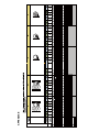
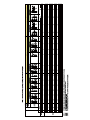
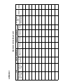
User manual
5 Check for Malfunction 5.1 General outline There are many factors which may cause the generator set’s malfunction, and the malfunctions are usually closely related to each other. This section mainly summarize and list the possible malfunctions of general diesel generator sets. This is just for user’s reference when they try to eliminate the malfunction(s). (Especially important for new generator set’s customer) One thing must to be emphasized: most of the malfunctions are caused by user’s improper installation, operation, and maintenance. Users are entitled to doubt that the malfunction(s) is caused by the generator set’s manufacture failure, but this conclusion shall be based on correct installation, operation and periodically maintenance. Otherwise, we can not assure you the normal operation of the generator set and the deserved after sales service. 5.2 Malfunction checklist 20
APPENDIX E
1
2
3
Generator set running record
TIME
ENGINE PARAMETER
GENERATOR PARAMETER
IF RECORD
FOR
Start/stop Accumulated
OPERATOR REMARK
Oil
Temperature Voltage Current Frequency Power MALFUNCTION
generator
running
pressure
IS AVAILABLE
set time
time
APPENDIX F
APPENDIX G
Maintenance Record
Maintenance Time:
Generator set model:
Engine model:
SN:
Alternator Model:
Generator set serial No.:
Engine serial No.:
Alternator serial No.:
Accumulated running hours:
Maintenance cycle:
Reasons for maintenance (periodic maintenance or malfunction maintenance)
Inspection and repair
Inspection and adjustment
Change of parts
Clean and maintenance
Others
Conclusion for maintenance:
Maintenance staff signature:
APPENDIX H