1
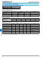
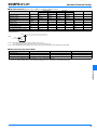
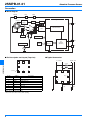
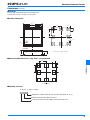
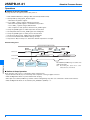
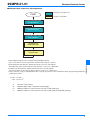
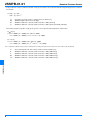
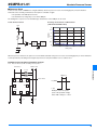
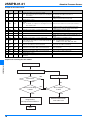
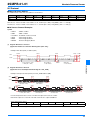
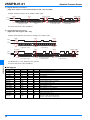
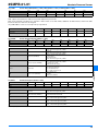
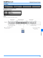
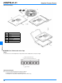
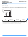
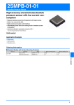
2SMPB-01-01
Absolute Pressure Sensor
High accuracy and small size absolute
pressure sensor with low current consumption
• Measure absolute pressure and temperature with high accuracy.
• Built in low noise 24 bits ADC.
• Digital control and output via I2C interface
• Automatically power down non working circuit to minimize current
consumption
• Individual calibration parameters stored in OTP *.
* One Time Programmable Non Volatile Memory
RoHS compliant
Application Example
• Smart Phone
• Activity monitor
• Wearable device
Ordering Information
■ Standard Models with Surface Mounting Terminals
8-pin QFN
Packaging
Model
Minimum Order Quantity
Minimum Packing Unit
Tape and Reel
2SMPB-01-01-TR
1,000
1,000
Embossed Carrier Tape
2SMPB-01-01
10
10
2SMPB-01-01
Structure
1
2SMPB-01-01
Absolute Pressure Sensor
Ratings, Specifications, and Function
■ Use conditions and recommended operating conditions
Type of Pressure
Absolute pressure
Medium
Air *
Operating Pressure Range
30 kPa to 110 kPa
* Never use corrosive gases.
■ Absolute Maximum Ratings
Item
Power Supply Voltage
Symbol
Rating
Vddmax
Unit
4.0
Remark
V
Input Voltage (other than power)
Vmax
-0.2 to Vopr+0.2
V
Maximum Pressure
Pmax
160
kPa
Storage Temperature
Tstr
-40 to 85
°C
with no condensation or icing
Storage Humidity
Hstr
10 to 95
%RH
with no condensation
■ Operating Ratings
Item
Operating Voltage
Operating Temperature
Symbol
Min.
Typ.
Max.
Unit
Remark
Vopr
2.25
2.5
3.6
V
VDD
Vddio
1.62
2.5
3.6
V
VDDIO
Topr
-40
-
85
°C
■ Electrical Characteristics (At Ta = 25°C, VDD = 2.5 V, unless otherwise noted)
2SMPB-01-01
Item
Name
Min.
Typ.
Max.
Unit
Average Current *
Ihp
-
9
-
µA
Current Consumption
Idd
-
500
610
µA
Sleep Mode Current Consumption
Isleep
-
0.3
0.6
µA
Measureable Pressure Range
Popr
30
-
110
kPa
Remarks
1 sample/s High accuracy mode
Absolute Pressure Accuracy *
Pabs1
-750
-
750
Pa
Relative Pressure Accuracy *
Prel1
-
6
-
Pa
70 k to 110 kPa High accuracy mode
70 k to 110 kPa High accuracy mode
rms Noise *
Pnois
-
2
-
Pa
70 k to 110 kPa High accuracy mode
Absolute Temperature Accuracy
Tabs
-2
-
2
°C
Pressure Resolution *
Pres
-
0.06
-
Pa
High accuracy mode
Temperature Resolution *
Tres
-
0.0002
-
°C
High accuracy mode
Discharge time of VDD *
Toff
-
60
-
sec
Time@ VDD From 2.5 V to 0.01 V
* These characteristics are guaranteed by design.
Note: Above table shows the characteristics without mounting board.
Please confirm performance of this sensors in your application and use your own judgment to determine the appropriateness of using them in such application.
2
2SMPB-01-01
Absolute Pressure Sensor
■ I2C Characteristics (At Ta = 25°C, VDD = 2.5 V, unless otherwise noted)
Item
Standard Mode
Name
MIN.
Fast Mode
MAX.
MIN.
Unit
MAX.
SCLK Clock Frequency
fscl
-
100
-
400
kHz
Digital Input L (I2C)
Vil2
-0.2
VDD×0.2
-0.2
VDD×0.2
V
Digital Input H (I2C)
Vih2
VDD×0.8
VDD+0.2
VDD×0.8
VDD+0.2
V
Digital Output L (I2C)
Vol2
0
0.4
0
0.4
V
Pull-up Resister
Rpullup
2.2
10
2.2
10
kΩ
Capacitive Load
Cb
-
400
-
400
pF
Power On Supply Startup Waiting Time Tpor
-
0.8
-
0.8
msec
Power On Start Up Time
tstart
-
2
-
2
msec
Pulse Width of Asynchronous Reset
trar
100
-
100
-
µsec
Remark
Power On Reset
2.4 V
VDD
0.1 V
Tpor
Note 1: When the power is turned on, please activate power on reset.
For more information, please refer to the section of “Power on Reset” (p. 8).
Note 2: About detailed I2C bus information, please refer to the I2C-bus specification and user manual presented by NXP.
■ Characteristics by Power Mode
Mode *1
Waiting Time [msec] *2
Average Current @1 sample/s [µA] *2
rms Noise [Pa] *2
Low power mode
7
4
6
Standard mode
9
5
3
High accuracy mode
17
9
2
Please see “I2C_SREQ: Sensor Request Register” (p. 13) for setting up power mode.
Please see “Execute timing chart” (p. 6) for meaning of waiting time. These characteristics are guaranteed by design.
2SMPB-01-01
*1.
*2.
3
2SMPB-01-01
Absolute Pressure Sensor
Connection
■ Block Diagram
VDDIO
VDD
GND
3
2
8
Voltage
Supply
BG
Logic Block
Vsensor
VREF
5 RST
+
ΔΣ
ADC
DIGITAL FILTER
-
PTAT
CLK Gen.
7 SDA
POR
Vsensor, Vcm
I2C
(100 kHz
/400 kHz)
N.V.
Memory
6 SCL
4
1
TESTA
VPP
■ Pin Description and Layout (Top view)
7
6
5
■ Typical Connection
VDDIO VDD
I2C Interface
2SMPB-01-01
4.7 kΩ
4
8
4.7 kΩ
1 pin Mark
Pin No.
1
2
Symbol
3
7
Description
8
1
VPP
2
VDD
Power
3
VDDIO
Digital I/O Power
4
TESTA
Analog out for test *
5
RST
Asynchronous reset
6
SCL
I2C clock
7
SDA
I2C data
8
GND
Ground
N.C.
5
N.C.
4
OTP write enable *
* These pins are for test purpose only.
Please leave open (Non-connect) while operating.
4
6
N.C.
1
2
3
1 µF
1 µF
2SMPB-01-01
Absolute Pressure Sensor
Dimensions (Unit: mm)
■ Package
Package Type: QFN (Quad Flat No-lead package) 8 pin
Package Size: 3.8 mm × 3.8 mm × 1.0 mm (max.)
■ Outline Dimension
Top view
Bottom view
@3.80±0.10
@3.60±0.10
@2.90±0.10
1.50
0.60
0.60
1.50
1 pin
index
1 pin
Front view
0.92±0.08
0.72±0.08
Terminal surface material : Gold Plate
0.20±0.05
■ Mounting PAD Dimensions (Top View) : recommended
1.50
0.70
2SMPB-01-01
0.70
1.50
PCB Land Pad
■ Marking structure
P B 0 1 (Type : Fixed)
Sequence number (from 0 to 9, from A to Z (without O, Q, I))
Week of manufacture (from 01 to 5*)
Year of manufacture (One digit at the end of the year)
5
2SMPB-01-01
Absolute Pressure Sensor
Operations
■ Outline of Sensor Operation
This page describes the typical operation after power on.
1. Wait until OTP initialization. (waiting for OTP automatically initialize finish)
2. Start-up ADC by setting up I2C_SETUP register
- Write 02h in I2C_SETUP register.
3. Access COE_* registers and get calibration parameters.
- Write 25h in I2C_AADJ register to enable OTP read operation.
- Access COE_* registers and get calibration data.
- After completion of read operation, write 65h to I2C_AADJ register.
4. Set up I2C_SREQ register to enable temperature measurement.
5. Get temperature data from I2C_TXD0 register after waiting time.
6. Set up I2C_SREQ register to enable pressure measurement.
7. Get pressure data from I2C_TXD0 register after waiting time.
8. Correct measured data with calibration data got at step 3.
9. Repeat 6 to 8. May need step 4, 5, and 8 when ambient temperature is changed.
Execute timing chart
Waiting time (Note)
Select
Pressure
I2C Access
I2C_SREQ
Internal Data
Read
Pressure
I2C_TXD0
Select
PTAT
Read
PTAT
I2C_SREQ
Valid pressure data
Valid PTAT data
Sleep_mode
2SMPB-01-01
Default
Is Sleep
Wake up after
I2C access
Sleep
Automatically
I2C and OTP (N.V.Memory) are active even
under sleep mode.
Note: About waiting time, please refer to section
“Characteristics by Power Mode.
■ Outline of Sleep Operation
Sleep operation of this sensor is controlled by start/stop internal clock.
• System will automatically stop clock and sleep after completion of analog to digital conversion.
• ADC and Digital Filter Block are powered down while sleeping.
• Other part such as OTP (N.V.Memory) and I2C continue working during sleep, then can communicate outside via I2C interface.
• ADC and Digital Filter Block can be awaken by I2C_SREQ bit 4 (ACTBIT) = “1”.
6
2SMPB-01-01
Absolute Pressure Sensor
■ Compensation of pressure and temperature
START
: Read Values through I2C I/F
: Calculate outside MCU
(1) Read Calibration Data
from N.V Memory
(2) Read Uncompensated
Temperature Value
(3) Read Uncompensated
Pressure Value
(4) Compensate
Temperature Value
(5) Compensate
Pressure Value
• Read calibration data which are contained in internal NVM through I2C.
These coefficients are used at compensation calculation below step (4) or step (5).
This temperature data is used at step (4) using coefficients of step (1) for compensation.
• Read pressure data which are output by absolute pressure sensor through I2C.
This pressure data is used at step (5) using coefficients of step (1) for compensation.
• Using coefficients of step (1) and temperature data of step (2), the operator corrects temperature data by using following temperature
compensation formula.
Tr = (Dt – ca) × ba0
= (Dt – ca) × ba × 2-19
Tr:
Calculation result [1/256°C]
Dt:
2SMPB-01 digital output of temperature (internal) [digit]
ba:
2SMPB-01 calibration coefficient (16 bits read value of COE_PTAT2 Reg)
ca:
2SMPB-01 calibration coefficient (24 bits read value of COE_PTAT3 Reg and COE_CEX Reg)
7
2SMPB-01-01
• Read temperature data which are output by absolute pressure sensor through I2C.
2SMPB-01-01
Absolute Pressure Sensor
• Using coefficients of step (1) and pressure data of step (3), the operator corrects pressure data by using following pressure compensation formula.
Pl = (Dp – cp) × bp0
= (Dp – cp) × bp × 2-19
Pl:
Calculation result. This result is a relative value from 90 kPa. [Pa]
Dp:
2SMPB-01 digital output of pressure [digit]
bp:
2SMPB-01 calibration coefficient (16 bits read value of COE_PR2 Reg)
cp:
2SMPB-01 calibration coefficient (24 bits read value of COE_PR3 Reg and COE_CEX Reg)
The next by using the result data of step (4), the operator corrects pressure data temperature compensation.
Ta
25 [°C]
Po = Pl + 90000 + (Pl + 90000) (ct0 + bt0 × Tr) - 90000
= Pl + 90000 + (Pl + 90000) (ct × 2-18 + bt × 2-31 × Tr) - 90000
Ta < 25 [°C]
Po = Pl + 90000 + (Pl + 90000) (ct20 + bt20 × Tr) - 90000
= Pl + 90000 + (Pl + 90000) (ct2 × 2-18 + bt2 × 2-31 × Tr) - 90000
2SMPB-01-01
Note: Temperature calibration of the pressure is calculated after converting to absolute pressure value because Pl is a relative value from 90 [kPa].
8
Po:
Final compensated result. This result is a relative value from 90 kPa. [Pa]
bt:
2SMPB-01 calibration coefficient (16 bits read value of COE_TEMP2 Reg)
ct:
2SMPB-01 calibration coefficient (16 bits read value of COE_TEMP3 Reg)
bt2:
2SMPB-01 calibration coefficient (16 bits read value of COE_TEMP22 Reg)
ct2:
2SMPB-01 calibration coefficient (16 bits read value of COE_TEMP23 Reg)
2SMPB-01-01
Absolute Pressure Sensor
■ Power on Reset
Power-on reset circuit of 2SMPB-01 is using the CR delay. Therefore power-on reset is not working properly on below situations.
At the time of the following circumstances when power is switched on again:
• The potential of the VDD pin is not 0 volt.
• The instantaneous voltage drop occurs in the VDD pin.
Circuit diagram of a power-on reset and discharge characteristics of the VDD pin are as follow.
Power On Reset Circuit
Discharge characteristic of VDD Terminal
(VDD Terminal OPEN at OFF)
VDD
3
VDD [V]
2.5
2
1.5
1
Reset
circuit
Digital
clock
0.5
0
0
Reset
pulse
20
40
time [sec]
60
80
When the power is turned on, the power-on reset should be activated. If the power-on reset is not working properly, it can be returned to
normal operation by executing reset using the asynchronous reset pin, hardware reset or software reset.
Example of reset using the asynchronous reset pin
Note: Please fix the No.5 pin into Low during normal operation.
I2C Interface
VDDIO VDD
100 µsec
4.7 kΩ
7
6
2SMPB-01-01
4.7 kΩ
Reset Pulse
5
H (VDD)
2SMPB-01-01
8
N.C.
4
L (0)
N.C.
1
2
Examples of the reset pulse
3
(reset at the potential of High)
Pulse width : 100 µsec. or more
1 µF
1 µF
9
2SMPB-01-01
Absolute Pressure Sensor
Example of the software reset
No.
Register Operation
1
0x05
Read
2
0x03
Write
Write
address
I2C Order MCU Operation
Explanation
(search slave address of module by I2C_FIND0)
Run for the searched slave address below.
Note: Refer to the next section of sequence for searching the
The searched slave address is shown as Y.
slave address
0x10
3
Single operation
Setting low power mode for for clear early
Write 0x10 to slave address Y, resister address 0x03
Waiting 20 msec or more
4
0x05
Read
5
0x04
Write
Find the slave address of the module using the I2C_FIND0
register
Run for the slave address that searched, slave address is Y
Note: For details, see sequence for searching the slave address in next section
0x50
To ASIC forced mode of operation (internal clock starts
oscillating) => It is required for writing to 0x07 address
Write 0x50 to slave address Y, resister address 0x04
6
0x0A
Write
0x02
Write 0x02 to slave address Y, resister address 0x0A
Normal initialization of Setup register
7
0x0C
Write
0x00
Write 0x00 to slave address Y, resister address 0x0C
Normal initialization of IOTEST register
8
0x08
Write
0x25
Write 0x25 to slave address Y, resister address 0x08
Change AADJ resister, transision to OTP read mode
Waiting 10 msec or more
Waiting of transission to OTP read mode (Waiting time can
afford)
9
10
0x09
Write
0x22
Write 0x22 to slave address Y, resister address 0x09
Normal initialization of WAKEUP register
11
0x30
Read
Read 16 bit from slave address Y, resister address 0x30, and
save as Z upper 8 bits.
Trimming value of W/T results acquisition
Note: It is required OTP read mode on
8 Address of Z are 0x01, 0x02, 0x03...0x0F.
12
0x07
Write
Write Z to slave address Y, resister adress 0x07
In particular, run the I2C communication less than 100 kHz.
Henceforth, slave address return 0x70.
13
0x04
Write
0x10
Write 0x10 to slave address 0x70, resister address 0x04
Normal initialization of MODESEL register ASIC ; sleep mode,
DSP ; nomal mode
14
0x08
Write
0x65
Write 0x65 to slave address 0x70, resister address 0x08
Normal initialization of AADJ register
15
0x03
Write
0x16
Write 0x16 to slave address 0x70, resister address 0x03
Single operation on high accuracy mode
16
Waiting 20 msec or more
17
Reset program of absolute pressure sensor module
termination
Sequence for searching the slave address
2SMPB-01-01
Slave address 0x70
Read 8 bits data from 0x05
NO
+1 on slave address
Return Ack
YES
Result of Reading
is 0x5A
YES
The current value is
recognized as
subsequent Slave Address.
End
10
NO
NO
Slave address
is 0x7F
YES
Abnormal termination,
error code issue
2SMPB-01-01
Absolute Pressure Sensor
I2C Protocol
■ About I2C Slave Address
The 2SMPB-01-01 module I2C slave address is shown below.
Bit
bit7
Value
bit6
bit5
bit4
bit3
bit2
bit1
bit0
Add [6]
Add [5]
Add [4]
Add [3]
Add [2]
Add [1]
Add [0]
R/W
1
1
1
0
0
0
0
1/0
Write Access : Please set LSB of slave address as “0”, and this byte is E0h (1110_0000b). (70h << 1 + WR (0))
Read Access : Please set LSB of slave address as “1”, and this byte is E1h (1110_0001b). (70h << 1 + RD (1))
■ I2C Access Protocol Examples
Symbol
• START
: START condition
• STOP
: STOP condition
• Re-START : Re-START condition for Read
• SACK
: Acknowledge by Slave
• MACK
: Acknowledge by Master
• MNACK
: Not Acknowledge by Master
(1) Register Write Access Protocol
(Application: Addresses other than OTP Registers (20h - 34h) )
Example: Write data (8 bits) to address (03h)
START
SACK
SACK
SACK
STOP
SDA
SCLK
6
5
4
3
2
1
0
7
6
Device Address + W/R
=> E0h (70h + “WR”)
5
4
3
2
1
0
7
6
SACK
Word Address
=> 03h Address
5
4
3
2
1
0
Write Data
=> 1Ch WR data
2SMPB-01-01
7
(2) Register Read Access Protocol
(Application: Pressure/Temperature Data Register = I2C_TXD0 )
Example: Read pressure data (24 bits) from I2C_TXD0=address (00h).
START
SDA
SCLK
SACK
7
6
5
4
3
2
1
0
SACK
7
6
Device Address + W/R
E0h (70h + “WR”)
Re-START
5
4
3
2
1
0
Word Address
00h Address
SACK
MACK
MACK
MNACK STOP
SDA
SCLK
7
6
5
4
3
2
1
0
Device Address + W/R
=> E1h ( 70h + “RD”)
7
6
5
4
3
2
1
0
Read Data (H, 8 bits)
12h Read data
7
6
5
4
3
2
1
Read Data (L, 8 bits)
34h Read data
0
7
6
5
4
3
2
1
0
Read Data (XL, 8 bits)
56h Read data
Pressure/Temperature data consists of 24 bits and output as three blocks of 8 bits.
Data will be output as H, L and XL order and each 8 bits also output as MSB first.
24 bits data format is below.
Bit
Data
Bit23
...
Bit16
Bit15
Read Data H
...
Read Data L
Bit8
Bit7
...
bit0
Read Data XL
In order to read only data (L) or data (XL), use next protocol (3).
11
2SMPB-01-01
Absolute Pressure Sensor
(3) Register Read Access Protocol
(Application: Addresses other than OTP Registers (20h - 34h), I2C_TXD0.)
Example: Read data (8 bits) from I2C_SREQ = address (03h)
SDA
START
SCLK
SACK
7
6
5
4
3
2
1
0
SACK Re-START
7
6
Device Address + W/R
=> E0h (70h + “WR”)
5
4
3
2
1
0
7
Word Address
=> 03h
SACK
6
5
4
3
2
1
MNACK STOP
0
7
Device Address + W/R
=> E1h (70h + “RD”)
6
5
4
3
2
1
0
Read Data (L side 8 bits)
=> 35h RD data
Each 8 bits data will be output as MSB first.
(4) Register Read Access Protocol
(Application: OTP Registers (20h - 34h))
Example: Read calibration data (16 bits) from COE_PR2 = address (22h).
SDA
START
SCLK
SACK
7
6
5
4
3
2
1
0
SACK
7
6
Device Address + W/R
=> E0h (70h + “WR”)
5
4
3
2
1
0
Word Address
=> 22h Address
Re-START
SACK
MACK
MNACK STOP
SDA
SCLK
7
6
5
4
3
2
1
0
7
Device Address + W/R
=> E1h (70h + “RD”)
6
5
4
3
2
1
0
7
Read Data (H, 8 bits)
=> 12h Read Data
6
5
4
2SMPB-01-01
■ I2C Register
Register Name
Address
00h
Bits
R/W
Default
8 bits
R/-
00h
Contents
Data Register MSB (24-17 bits)
I2C_TXD1
01h
8 bits
R/-
00h
Data Resister LSB (16-9 bits)
I2C_TXD2
02h
8 bits
R/-
00h
Data Resister XLSB (8-1 bits)
I2C_SREQ
03h
8 bits
R/W
00h
Sense Request
I2C_AADJ
08h
8 bits
R/W
65h
OTP Read Register
I2C_SETUP
0Ah
8 bits
R/W
00h
Setup Register
COE_PR2
22h
16 bits
R/-
00h
Pressure Linearity Calib.2: 1st Coefficient
COE_PR3
24h
16 bits
R/-
00h
Pressure Linearity Calib.3: offset
COE_TEMP2
26h
16 bits
R/-
00h
Temp Calibration 2: 1st Coefficient
COE_TEMP3
28h
16 bits
R/-
00h
Temp Calibration 3: offset
COE_TEMP22
2Ah
16 bits
R/-
00h
Temp Calibration 2-2: 1st Coefficient-2
COE_TEMP23
2Ch
16 bits
R/-
00h
Temp Calibration 2-3: offset-2
COE_PTAT2
2Eh
16 bits
R/-
00h
PTAT Linearity Calib.2: 1st Coefficient
COE_PTAT3
32h
16 bits
R/-
00h
PTAT Linearity Calib.3: offset
00h
Pressure & PTAT Linearity extend bits
Bit [15:8] => COE_PR3 extend bit [23:16]
Bit [7:0] => COE_PTAT3 extend bit [23:16]
COE_CEX
12
34h
16 bits
R/-
2
Read Data (L, 8 bits)
=> 34h Read Data
Set VBGACT bit “L” of I2C_AADJ before this operation.
Each 8 bits data will be output as MSB first.
I2C_TXD0
3
1
0
2SMPB-01-01
I2C_TXDx:
Absolute Pressure Sensor
Sensor Data TXD0 (Address = 00h), TXD1 (Address = 01h) or TXD2 (Address = 02h)
Bit
bit23
bit22
bit21
...
bit2
bit1
bit0
R/W
R/-
R/-
R/-
...
R/-
R/-
R/-
Initial
0
0
0
...
0
0
0
ADC output is stored with 22 to 24bit accuracy which depend on power mode.
Data can be retrieved as 24 bits by one operation. If data consists of less than 24 bits, additional “0” will be filled as shown in the table
below. The data are read out in an unsigned.
I2C_TXD0 address can be accessed by memory map method.
Bit
23
22
21
...
3
2
1
0
22 bits data (Low power mode)
valid
valid
valid
...
valid
valid
0
0
24 bits data
(Standard & High Accuracy mode)
valid
valid
valid
...
valid
valid
valid
valid
I2C_SREQ:
Sensor Request Register (Address = 03h)
bit7
bit6
bit5
bit4
bit3
bit2
bit1
bit0
R/W
Resv
Resv
R/-
-/W
R/W
R/W
R/W
R/W
Initial
0
0
0
0
0
0
0
0
Bit7
Reserved
Reserved.
Set “0” when write register I2C_SREQ
Bit6
Reserved
Reserved.
Set “0” when write register I2C_SREQ
Bit5
Sleep state (SLEEPST)
Indicate operation mode while reading.
1: sleep mode
0: operating mode
Set “0” when write register I2C_SREQ
Bit4
Wake up request (ACTREQ)
Control sleep mode.
Set “1” when write register I2C_SREQ.
1: Awaken the system
0: Not awaken the system
Bit3 to 1
Mode select
Select measurement mode.
“0_0_0” Low power mode
“0_1_0” Standard mode
“0_1_1” High accuracy mode
Bit0
Sensor select (PTATSEL)
Sensor Input Select
1: PTAT
0: Pressure (Default)
2SMPB-01-01
Bit
Note: Proper operation will not be assured with bit combination not specified above.
I2C AADJ:
OTP Read Register (Address = 08h)
Bit
bit7
bit6
bit5
bit4
bit3
bit2
bit1
bit0
R/W
Resv
R/W
Resv
Resv
Resv
Resv
Resv
Resv
Initial
0
1
1
0
0
1
0
1
Bit7
Reserved
Reserved.
Set “0” when write register I2C_ADDJ
Bit6
OTP Read Mode (VBGACT)
0: OTP Read Enabled
1: OTP Read Disabled (Default)
Bit5 to 4
Reserved
Reserved.
Set “1_0” when write register I2C_ADDJ.
Bit3 to 2
Reserved
Reserved.
Set “0_1” when write register I2C_ADDJ.
Bit1 to 0
Reserved
Reserved.
Set “0_1” when write register I2C_ADDJ.
Note: Proper operation will not be assured with bit combination not specified above.
13
2SMPB-01-01
I2C_SETUP:
Absolute Pressure Sensor
Set Up Register (Address = 0Ah)
Bit
bit7
bit6
bit5
bit4
bit3
bit2
bit1
bit0
R/W
Resv
Resv
Resv
Resv
Resv
Resv
R/W
R/W
Initial
0
0
0
0
0
0
1
0
bit7 to 2
Reserved
Reserved.
Set “0” when write register I2C_SETUP
bit1 to 0
Setup
ADC Power Up Mode
“1_0”: Start ADC Setup (Default)
“0_0”/“0_1”/“1_1”: Please DO NOT USE
Note 1: This set-up is required to start ADC operation.
Note 2: Proper operation will not be assured with bit combination not specified above.
COE_PR*:
Calibration Data Register for Pressure Linearity (OTP Register) (Address = 22h to 24h)
Bit
bit15
bit14
bit13
...
bit3
bit2
bit1
R/W
R/-
R/-
R/-
...
R/-
R/-
R/-
bit0
R/-
Initial
0
0
0
...
0
0
0
0
Read only. Calibration data is stored.
The data are read out in an unsigned.
I2C_AADJ bit6 (VBGACT bit) should be set to “0” to enable read operation of these OTP registers.
COE_TEMP*:
Calibration Data Register for Temperature Correction of Pressure (OTP Register) (Address = 26h to 2Ah)
Bit
bit15
bit14
bit13
...
bit3
bit2
bit1
R/W
R/-
R/-
R/-
...
R/-
R/-
R/-
bit0
R/-
Initial
0
0
0
...
0
0
0
0
bit0
Read only. Calibration data is stored.
The data are read out in an unsigned.
I2C_AADJ bit6 (VBGACT bit) should be set to “0” to enable read operation of these OTP registers.
2SMPB-01-01
COE_PTAT*:
Calibration Data Register for PTAT Linearity (OTP Register) (Address = 2Ch to 32h)
Bit
bit15
bit14
bit13
...
bit3
bit2
bit1
R/W
R/-
R/-
R/-
...
R/-
R/-
R/-
R/-
Initial
0
0
0
...
0
0
0
0
Read only. Calibration data is stored.
The data are read out in an unsigned.
I2C_AADJ bit6 (VBGACT bit) should be set to “0” to enable read operation of these OTP registers.
COE_CEX:
Calibration Data Register for Extend Bits for PR3 & PTAT3 (OTP Register) (Address = 34h)
Bit
bit15
bit14
bit13
...
bit3
bit2
bit1
R/W
R/-
R/-
R/-
...
R/-
R/-
R/-
R/-
Initial
0
0
0
...
0
0
0
0
Read only. Calibration data is stored.
The data are read out in an unsigned.
Bit15 to 8: These bits are extend bits of COE_PR3 register.
Bit7 to 0: These bits are extend bits of COE_PTAT3 register.
I2C_AADJ bit6 (VBGACT bit) should be set to “0” to enable read operation of these OTP registers.
14
bit0
2SMPB-01-01
Absolute Pressure Sensor
Packaging
Model
Packaging
Minimum Order Quantity
Minimum Packing Unit
2SMPB-01-01-TR
Tape and Reel
1,000
1,000
2SMPB-01-01
Embossed Carrier Tape
10
10
■ 2SMPB-01-01-TR / Tape and Reel
Configuration of shipment
Packaging
Embossed Carrier Tape
Quantity
SPQ 1,000 pcs
Max. 5,000 pcs/reel
1 reel / 1 Interior box
Reel model
EIAJ reel (330 mm dia.)
Insert method
see below
Taping
Emboss pitch 4 mm type & tape width 12 mm type
Trailer (no Sensor)
500 - 550 mm
Embossed Carrier Tape
Sensor housing unit
Leader (no Sensor)
540 - 590 mm
Core side
of the reel
540 mm - 550 mm
(The same dimensions as
the embossed carrier tape)
540nm or more
Cover Tape
Cover Tape (no Sensor)
Cover Tape (no Sensor)
1 pin mark
in the upper left
Direction to pull out
2SMPB-01-01
Core side of the reel
15
2SMPB-01-01
Absolute Pressure Sensor
Individual packaging
(1)
(4)
(5)
(2)
(4)
(3)
(6)
2SMPB-01-01
No.
Item
(1)
EIAJ reel
(2)
Desiccant
(3)
Reel band
(4)
Identification tag
(5)
Humidity indicator
(6)
Aluminum bag
(7)
Individual packing box
(7)
■ 2SMPB-01-01 / Embossed Carrier Tape
Taping
To ensure the reel for small shipment, the tape will be cut into multiple units of 10 pieces length.
Embossed Carrier Tape
Sensor housing unit (10 pcs) × n
Cover Tape
Individual packing box
These are chosen the packaging box following two patterns.
• Packing small reel cut type in the box with air cap.
• Packing the reel cut products shaped ring in the box with air cap.
16
2SMPB-01-01
Absolute Pressure Sensor
Recommended Soldering Method
■ Soldering method
air reflow (Max. 2 times)
■ Condition of Temperature
Max. 260°C, within 10 seconds
■ Recommended Soldering Method
Temperature profile conditions of reflow soldering should be set as shown in the below table, and then confirm that actual conditions
Temperature (°C)
coincide with the conditions shown in the table.
T4
T3
T2
T1
t1
Preheating
t2
Soldering
Time (s)
Preheating (T1 to T2, t1)
Soldering (T3, t2)
Peak value (T4)
150°C to 180°C 120 s max.
230°C min. 30 s max.
250°C max.
Upper surface of case
-
-
255°C max.
2SMPB-01-01
Item
Terminal
• We recommend a thickness of 150 to 200 µm for the solder cream.
• Since the pressure sensor chip is exposed to atmosphere, cleaning fluid shall not be allowed to enter inside the sensor’s case.
• We recommend that the recommended mounting PAD dimensions should be used for the land pattern.
17
2SMPB-01-01
Absolute Pressure Sensor
Safety Precautions
Precautions for Correct Use
Handling
(1) Only air can be used as pressure media on the product directly. It is prohibited to use pressure media including corrosive gases (e.g.
organic solvents gases, sulfur dioxide and hydrogen sulfide gases), fluid and any other foreign materials.
(2) The product are not water proof. The product shall be kept dry in use including the sensor port.
(3) The product shall not be used under dew-condensing conditions. Frozen fluid on sensor chips may cause fluctuation of sensor output and other troubles.
(4) The product shall be used within rated pressure. Usage at pressure out of the range may cause breakage.
(5) The product may be damaged by static electricity. Charged materials (e.g. a workbench and a floor) and workers should provide
measures against static electricity, including ground connection.
(6) Overpowering pins may deform terminals and detract solder abilities of sensor terminals. The product shall not be dropped and handled roughly.
(7) The product shall not be used under dusty or damp condition.
(8) Please connect the sensor terminals according to the connection diagram.
(9) The product shall not be used under high-frequency vibration including ultrasonic wave.
(10) This product uses the elastic adhesive for bonding the lid, so do not add excessive stress to the lid.
(11) If you use other conditions described in this document, please check yourself in advance.
Environmental conditions for transport and storage
(1) The product shall not be kept with corrosive gases (e.g. organic solvents gases, sulfur dioxide and hydrogen sulfide gases).
(2) The product are not water proof. The product shall be kept dry during storage.
(3) By condition of the place and storage period, there are cases that strength of outer boxes may be degraded. Please use the product
in order.
(4) For this product, please keep away from direct sunlight or ultraviolet rays.
(5) The product shall be kept in appropriate conditions of temperature and humidity.
(6) Sometimes the color of terminals of the product may change depending on the conditions. It is not covered under warranty.
(7) The product shall not be kept under dusty or damp condition.
2SMPB-01-01
Note: Specifications in this document are subject to change without notice.
• Application examples provided in this document are for reference only. In actual applications, confirm equipment functions and safety before using the product.
• Consult your OMRON representative before using the product under conditions which are not described in the manual or applying the product to nuclear control systems, railroad
systems, aviation systems, vehicles, combustion systems, medical equipment, amusement machines, safety equipment, and other systems or equipment that may have a serious
influence on lives and property if used improperly. Make sure that the ratings and performance characteristics of the product provide a margin of safety for the system or
equipment, and be sure to provide the system or equipment with double safety mechanisms.
Note: Do not use this document to operate the Unit.
OMRON Corporation
Electronic and Mechanical Components Company
18
Contact: www.omron.com/ecb
Cat. No. A233-E1-03
0615(0614)(O)