1
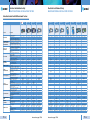
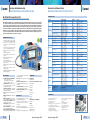
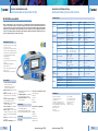
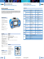
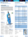
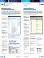
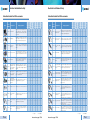
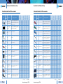
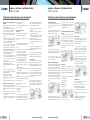
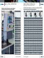
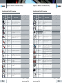
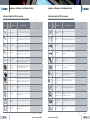
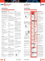
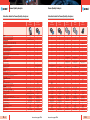
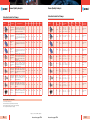
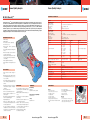
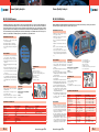
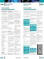
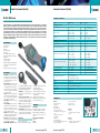
Electrical Installation Safety GOOD TO KNOW Electrical Installation Safety GOOD TO KNOW Electrical Installation Safety Testing Electrical Installation Safety Testing Find out more about testing safety of electrical installations According to European standards requirements electrical installation safety testing includes a combination of following tests: •Insulation resistance, •Continuity of protective conductors and equipotential bonding, •RCD testing, •Line and fault loop impedance, •Earth resistance testing (two-wire method without probes, three / fourwire method with two probes, method with current clamp and two probes, method with two current clamps) •Specific earth resistance, •Phase sequence, voltage and frequency. With this function all relevant RCD tests can be carried out in one step which is very simple and time saving feature. These tests are performed in order to ensure that the requirements are met for the protection of persons, livestock and property against the risk of electric shock and to ensure that the automatic disconnection of the supply is performed correctly. Insulation resistance The insulation is intended to prevent any contact with live parts and withstanding mechanical, chemical, electrical and thermal stresses. Insulation test discloses insulation faults caused by pollution, moisture, deterioration of insulation materials etc. Insulation resistance measurement is covered by the IEC / EN 61557-2 standard. The power must be switched off and the installation must be disconnected before performing this test to ensure that the test voltage will not be applied to other equipment electrically connected to the circuit to be tested, particularly devices sensitive to voltage surges. Insulation resistance shall be measured between: •Line conductors, •Line and PE conductors, •Line and Neutral conductors, •Neutral and PE conductors. Test circuit for insulation resistance measurement 1. 2 RCD selection table according to their sensitivity: AC type Test circuit for insulation resistance measurement The insulation resistance test is performed with a DC voltage on a dead system and the resistance must be above the minimum limit set out in the appropriate standards and regulations. Limit values for electrical installations acc. to IEC 60364-6: Ratedt voltage of circuit (V) DC test Insulation voltage (V) resistance (MΩ) LV secondary switchboard or LV main switshboard 250 ≥0.5 Less than or equal to 500 V including LV main switchboard 500 ≥1.0 1.000 ≥1.0 Greater METREL’s hint: EurotestAT and EurotestXA have built-in the “Insulation ALL” function which enables performing of 3-port insulation test (L-N, L-PE, N-PE or L1-L2, L1-L3, L2-L3) in one step. This is a very time saving feature especially if measuring insulation on outlets. Continuity of protective conductors and equipotential bonding The purpose of continuity measurement is to check the continuity of the protective conductors, the main and supplementary equipotential bonds. The test is carried out using a measurement instrument capable of generating a no-load voltage of 4 to 24 V (DC or AC) with a minimal current of 200 mA. U Test circuit for continuity R200 mA measurement METREL’s hint: EurotestAT and EurotestXA can perform the N – PE loop test between instrument’s N and PE test terminals. This makes testing with the plug test cable on outlets possible. U U t t t U U U Test circuit for continuous resistance measurement RCD testing RCD devices are used as protection against dangerous fault voltages and fault currents. Various test and measurements are required for verification of RCDs in RCD protected installations. Measurements are based on the EN 61557-6 standard. Scope of RCD test is: •to verify effectiveness and proper operation of the RCDs; •to verify disconnection times and trip out currents of RCDs; •to verify that there are no or limited present fault currents in the installation. The following measurements and tests of RCDs can be performed: •Contact voltage, •Trip-out time, •Trip-out current, •RCD autotest. t t No response No response No response t U U B type t t t Line impedance Line impedance is measured in loop comprising of mains voltage source and line wiring (between the line and neutral conductors or between lines on a 3-phase system). It is covered by requirements of the EN 61557-3 standard. Scope of line impedance test is: •to verify effectiveness of installed over current devices; •to verify internal impedance for supplying purpose. The line-neutral short circuit loop consists of: •Power transformer secondary impedance ZT, •ZL (phase wiring from source to fault), •ZN (neutral wiring from source to fault). The line to neutral impedance is the sum of impedances and resistances that forms the line to neutral loop. In three phase system there are three line-neutral impedances (ZL1-N, ZL2-N, ZL3-N). METREL’s hint: METREL installation testers have built-in tables with fuses and RCDs parameters. When line test is performed, the measured value is automatically compared to the maximum values set out in the standard (EN 61557) and either a PASS or FAIL symbol will appear on the screen to inform the user if the result is within the required limits. Fault loop impedance Fault loop is a loop comprising mains source, line wiring and PE return path to the mains source. The measurement is covered by requirements of the EN 61557-3 standard. Scope of loop impedance test is: •to verify effectiveness of installed over current and / or residual current disconnection devices; •to verify fault loop impedances, prospective fault currents and fault voltage values. In TN systems the fault loop ZL-PE consists of: •ZT (power transformer secondary impedance); •ZL (phase wiring from source to fault); •RPE (PE / PEN wiring from fault to source). The fault loop impedance is the sum of impedances and resistances that forms the fault loop. ZLN = ZL+ ZN+ZTLN Continuity test is covered by the EN 61557-4 standard. The measured resistance must be lower than a threshold specified by the standard applicable to the installation tested, which is usually 2 Ω. As the resistance value is low, the resistance of the measurement leads must be compensated, particularly if very long leads are used. U A type IPSC must be higher than current for rated disconnection time of the over current disconnection device. The line – neutral (or line - line) impedance should be low enough e.g. prospective short circuit current high enough that installed protection device will disconnect the short circuit loop within the prescribed time interval. The prospective short circuit current IPSC is defined as: ZLPE = ZL+ RPE+ZT The prospective fault current IPSC is defined as: Circuit for testing RCD METREL’s hint: METREL installation testers have built-in the “RCD AUTO” function which performs RCD testing at x1/2, x1 and x5 current multipliers at both 0° and 180° automatically. Accessories: page 1.60 ULN >Ia IPSC= ____ ZLN Circuit for measurement of line impedance Accessories: page 1.60 ULPE >Ia IPSC= ____ ZLPE Circuit for measurement of fault loop impedance METREL’s hint: METREL installation testers have built-in tables with fuses and RCDs parameters. When loop test is performed, the measured value is automatically compared to the maximum values set out in the standard (EN 61557) and either a PASS or FAIL symbol will appear on the screen to inform the user if the result is within the required limits. Earth resistance Earth resistance testing is used on TN, TT and IT systems to ensure that the resistance of the earth electrode is sufficiently low so that, in the case of a fault, a dangerous voltage does not appear on any parts of the installation or on any appliances which have a connection to earth. The measurement conforms to the EN 61557-6 standard. Scope of earth resistance test is: •Earthing of exposed conductive parts assures that the voltage on them stays below dangerous level in case of a fault. In TN installations the earthing is realized at the source and / or distribution points that’s why the earthing resistances are usually very low (below 1Ω). TT installations have their own main earthing. The resistances are usually higher than in TN systems (from few Ω up to several hundred Ω). Because of this dangerous fault voltages and body currents can occur at relatively low fault currents. Therefore TT systems usually have additional RCD protection. The following earth resistance measuring methods are available: •Standard 3-wire (4-wire) method for standard resistance to earth measurements; •3-wire (4-wire) method with one clamp, for measuring resistance to earth of individual earthing rods; •Two clamps method for measuring resistance to earth of individual earthing rods (recommended in IEC 60364-6 for urban areas); •Specific earth resistance (is carried out in order to assure more accurate calculation of earthing systems e.g. for highvoltage distribution columns, large industrial plants, lightning systems etc.). 1. 3