1
2.0 GENERAL DESCRIPTION
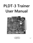
The XC95108 used in the PLDT-3 digital logic trainer is in-service programmable (ISP). ISP means that the
CPLD can be erased and reprogrammed while it is in a circuit, so a separate device-programmer box is not
required. The PLDT-3 is powered by a wall-mounted power module which comes with the trainer.
The PLDT-3 connects to the parallel port of a personal computer via a standard 25-wire cable with DB25
connectors at both ends (Figure 2, detail 8). The cable is part of the package when purchasing the PLDT-3.
Standard design software, such as XILINX Foundation or Xilinx WebPack, can be used.
Once commands are down-loaded from the PC to the CPLD, the cable may be disconnected; the CPLD
"remembers" the design. Or the cable can be left attached for rapid reconfiguration of the logic design. Either
way, the digital circuit programmed into the CPLD can be tested using the on-board switches and LEDs of the
PLDT-3 board. Most CPLD pins are brought out via connector blocks. An uncommitted 16-pin male header is
available for a user-defined ribbon-cable connection. Power, ground, and most CPLD pins are brought out to a
96-pin DIN-connector (P1), making the full power of the XC95108 available for advanced designs.
The 16 switches (8 toggle, 8 DIP) and 16 LEDs (8 red, 8 green) of the PLDT-3 can be accessed via jumper-blocks
as well as via pin-jacks (Figure 2, details 1, 2, 3) to allow connection of external circuits. Thus you can interface
to external circuits built with small-scale ICs, such as logic chips, micro-controllers, memory chips, A/D & D/A
converters, and so forth. Also on board the PLDT-3 are 4 momentary push-button switches (2 debounced and 2
not), an on-board 1 Hz clock, a 4 MHz clock module, a buffered input for an external clock, two 7-segment
displays, and an SR flip-flop with inputs and outputs available via pin-jacks. A terminal-block allows access to +5
Volts and ground.
•
Figure 2
6