1
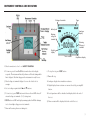
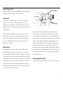
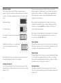
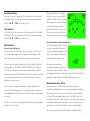
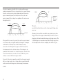
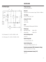
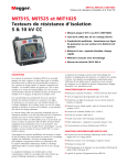
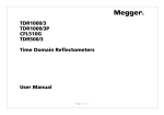
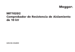
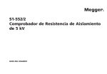
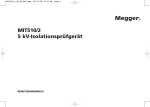
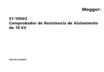
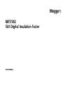
M
MIT510/2
5kV Digital Insulation Tester
USER MANUAL
G
SAFETY WARNINGS
Safety Warning must be observed during use.
n
The circuit under test must be switched off, de-energised, isolated and checked to be safe before insulation test connections are made. Make sure the
circuit is not re-energised whilst the instrument is connected.
n
Circuit connections must not be touched during an insulation test.
n
After completing a test, capacitive circuits must be completely discharged before disconnecting the test leads. Capacitive charges can be lethal.
n
Tested items should be firmly shorted out with a shorting link, after discharge, until required for use. This is to guard against any stored dielectric
absorption charge subsequently being released thereby raising the voltage to potentially dangerous levels.
n
The voltage indicator and automatic discharge features should be regarded as additional safety features and not a substitute for normal safe working
practice.
n
It is rare, but in certain circumstances, breakdown of the circuit under test may cause the instrument to terminate the test in an uncontrolled manner,
possibly causing a loss of display while the circuit remains energised. In this event, the unit must be turned off and the circuit discharged manually.
n
Test leads, including crocodile clips, must be in good order, clean and with no broken or cracked insulation.
n
The instrument should not be used if any part of it is damaged.
n
Insulation testing in wet weather conditions might be hazardous. It is recommended that this instrument is not used in these circumstances. If this is
unavoidable, the user must take all necessary precautions.
n
This instrument is not intrinsically safe and must not be used in hazardous atmospheres.
NOTE
THE INSTRUMENT MUST ONLY BE USED BY SUITABLY TRAINED AND COMPETENT PERSONS.
Users of this equipment and/or their employers are reminded that National Health and Safety Legislation requires them to carry out valid risk assessments of
all electrical work so as to identify potential sources of electrical danger and risk of electrical injury such as inadvertent short circuits. Where the assessments
show that the risk is significant then the use of fused test leads may be appropriate.
2
CONTENTS
Safety warnings
2
Cleaning3
Introduction4
Power lead and charging 4
Instrument controls and indicators
5
Power On/Off button
6
Test voltage s and t buttons
6
Test start/stop button
6
Ω/I button
6
B button
6
High voltage warning LED
6
Line input present LED
7
Test terminals
7
Guard terminal
7
Factory programming socket
7
Battery bar graph
8
Voltage at terminals
8
Timer indicator
8
Digital display
8
Analogue display
8
Capacitance display
9
Time constant
9
Noise detection
9
Measurements above 100 GΩ9
Circuit block diagram
10
Specification11
Accessories13
Repair and Warranty
14
Battery replacement
14
Symbols used on the instrument are:
F
Caution: risk of electric shock
G Caution: refer to accompanying notes
t Equipment protected throughout by Double Insulation (Class II)
c
Equipment complies with current EU directives.
Terms used in this manual
The word must is used to indicate that the instructions following should
be followed under all circumstances. Failure to follow these instructions
could result in damage to the instrument and / or a hazard to the operator.
The word should is used to indicate that the instructions indicate best
practice.
Cleaning
Disconnect the instrument and wipe it with a clean cloth slightly damped
with soapy water or Isopropyl alcohol (IPA).
3
INTRODUCTION
The MIT510/2 is a compact microprocessor controlled high voltage
d.c. insulation tester, powered by internal rechargeable battery or
mains supply. A comprehensive LCD display shows resistance, current,
capacitance, voltage and timer measurements digitally, with resistance
being shown in analogue as well.
POWER LEAD AND CHARGING
If the power lead supplied is not suitable for your type of mains outlet, do
not use an adaptor. Always use a power lead fitted with the correct plug.
NB: A plug severed from the power lead is a hazard if plugged into a live
socket. Severed plugs must be destroyed immediately.
n
Resistance or current measurement- front panel selectable
The instrument is fitted with a two-pin IEC60320 power inlet. Most power
leads are made with three-core cable so the ground connection will not
be used.
n
Resistance measurement range - 10 kΩ to 15 TΩ
Power lead cable colour coding:
n
Front panel selectable test voltages - 250 V, 500 V, 1000 V, 2500 V,
Features include:
5000 V
InternationalUSA
Earth/GroundYellow/Green Green
n
Incremental timer (minutes & seconds) – measures during test
n
Load capacitance measurement – displayed at end of a test
Neutral
Blue
White
n
LCD backlight – front panel selectable
Live (Line)
Brown
Black
n
Battery level/charging indicator
If using a fused plug ensure it is fitted with a 3 Amp fuse.
n
Mains (line) input presence LED
n
High voltage warning flashing LED shows when greater than 50 V
present on test leads
n
High voltage warning LCD “flash” shows when greater than 50 V present on test leads
n
4
8 hours continuous testing on full charge.
The instrument can be powered from 95 - 240 V rms, ±10% 50/60 Hz.
With power connected the battery will charge as long as a test is not in
progress. The Power On/Off button has a green LED which illuminates
when mains power is present.
For best battery lifetime, charge the battery after each use. A completely
exhausted battery will take 14 hours to recharge.
INSTRUMENT CONTROLS AND INDICATORS
Voltage at terminals
Timer
Battery level
Analogue
display
Warning
voltage at
terminals
Warning
voltage at
terminals
Digital
display
Time constant
Capacitance display
1. Check connections to load - see SAFETY WARNINGS
2. To turn on, press Power On/Off button and release after display responds. The instrument first will perform a self-check during which Ini is displayed. After Ini disappears the instrument is ready for use.
8. To stop the test press TEST button.
3. Check voltage at terminals display to be sure the load is safe to energise.
10. Analogue display shows insulation resistance.
9. Timer will stop.
4. Set test voltage required with Vs and Vt buttons.
11. Digital display shows resistance or current selected by pressing Ω/I button.
5. To start a test, press TEST button and release after red LED shows. If external voltage at terminals <50 V, testing starts.
12. Load capacitance will be calculated and displayed after the end of the test.
6. TEST button red LED and display warning symbols will flash during a test to show high voltage present at terminals.
13. Time-constant will be displayed after the end of the test.
7. Timer will count up from zero during test.
5
Power On/Off button
The instrument will only turn on if this button is pressed, held and then
released when the display responds. The instrument will not turn on if
the button is released before the display responds, or if the button is held
down for too long. This is a safety feature to prevent the instrument being
inadvertently turned on.
The instrument is turned off either by pressing the button again, or if the
instrument is running on the battery, by timing out after 10 minutes of
inactivity.
Upon switching the instrument on the display will first show ‘Ini’ while it
undergoes a self-checking routine. When Ini disappears, the instrument is
ready for use.
Test start / stop button
A test will only start if this button is pressed, held and then released as
soon as the red high voltage warning indicator LED lights. The LCD and
red LED high voltage warning indicators flash when the test starts.
A test will not start if the button is released before the red LED shows, or
pressed continuously for longer than 5 seconds. This is a safety feature to
prevent a test being started inadvertently.
The presence of a voltage greater than 50 V on the test leads is indicated
with flashing high voltage warning indicators. Testing is disabled if the
external voltage exceeds 50 V.
Testing will stop if the test start / stop button is pressed again.
Test voltage s and t buttons
Using these buttons one of five test voltages can be selected: 250 V, 500 V,
1 kV, 2.5 kV, and 5 kV. The selected voltage is shown on the display.
When a test has finished, the instrument will discharge the load, which
may take some time. The operator must always check the load has been
discharged before touching the test leads.
If there is an external voltage greater than 50 V on the test leads, the high
voltage warning indicators are flashed, and the display shows this voltage
instead. The instrument will not perform a test if this voltage is greater
than 50 V.
Ω/I button
Pressing this button toggles the digital display between the insulation
resistance and current.
During a test the display shows the actual voltage on the test leads. If the
test voltage is changed during a test, the new test voltage will be displayed
briefly.
When the test has stopped, the display continues to show the voltage
present on the test leads. Pressing either test voltage s or t button will
then display the test voltage immediately before the end of the test.
Pressing this button toggles the display backlight on and off.
6
B button
High voltage warning LED
This is a red LED next to the TEST button on the front panel. The LED
flashes when the voltage on the test inputs exceeds 50 V.
Line input present LED
This is a green LED next to the power On/Off button on the front panel. It
is illuminated whenever the mains power is connected.
Test terminals
There are three test terminals marked +, - and G. These terminals are
designed to accept only the test leads supplied. Shutters across the
terminals prevent accidental ingress of dirt and other objects. Test lead
plugs interlock with the shutters and are released by rotating the test lead
plug a quarter turn.
The Guard terminal is explained below and is only used in cases where
surface leakage currents need to be eliminated. Most measurements use
just the + and – terminals. The instrument’s internal voltage generator
drives the + terminal with respect to the – terminal, current being
measured in the – terminal.
Guard terminal
For basic insulation tests and where there is little possibility of surface
leakage affecting the measurement, it is unnecessary to use the guard
terminal i.e. if the insulator is clean and there are unlikely to be any adverse
current paths. However in cable testing for example, there may be surface
leakage paths across the insulation between the bare cable and the external
sheathing due to the presence of moisture or dirt. Where it is required to
remove the effect of this leakage, particularly at high testing voltages, a
bare wire may be bound tightly around the insulation and connected via
the third test lead to the guard terminal ‘G’.
The guard terminal is at the same potential as the negative terminal.
Since the leakage resistance is effectively in parallel with the resistance
to be measured, the use of the guard causes the current flowing through
surface leakage to be diverted from the measuring circuit. The instrument
therefore reads the leakage of the insulator, ignoring leakage across its
surface. The display will show ‘FUS’ if the internal guard terminal fuse is
found to have blown. The instrument must be switched off to clear the
message before further testing is permitted. The fuse should be replaced
by an authorised repairer. The instrument may be used in the mean time
if the guard terminal not used. Refer to notes regarding measurements
above 100 GΩ on page 9.
Factory programming socket
This is a 9 pin socket under the hinged cover and is not for customer use.
7
Battery bar graph
This is a battery symbol on the LCD display comprising 4 pairs of
segments. The battery is monitored continuously when the instrument
is turned on. The charge remaining in the battery is shown in the table
below.
If there is an external voltage greater than 50 V present, this will be
displayed regardless of changes made to the test voltage. In this case the
instrument will not perform a test. The high voltage warning indicators
flash, and the beeper sounds, to warn of the hazard until the external
voltage becomes less than 50 V.
Fully charged battery
50% charged battery
When testing, the voltage displayed is the voltage present at the test
terminals of the instrument. If the test voltage is changed, by pressing
either of the test voltage s and t buttons during a test, the new test
voltage is displayed momentarily.
Tests cannot be started, and the battery may fail
at any time.
After testing, the voltage displayed is the voltage present on the terminals.
To see what the voltage was immediately prior to the end on the test,
press either test voltage s or t buttons.
Symbol flashes when there is not enough charge
for a test. The instrument then turns itself
off
Timer indicator
The timer shows minutes and seconds. At the start of a test the timer will
start from zero and at the end of a test it will stop. The duration of the last
test remains on the display until another test is started.
When mains power is present the indicator shows the battery is being
charged by animating the segments of the bar graph.
Voltage at terminals
The test voltage will default to that selected in the previous test. If the
instrument has been switched off since the previous test, the test voltage
defaults to 250 V.
8
Digital Display
The digital display shows the resistance or current being measured during
a test. The Ω/I button toggles between the two. After a test the display
shows the last measurement made until the timer or voltage test settings
are changed or the test start/stop button is pressed.
Analogue display
This simulates an analogue meter movement to give the user a better
“feel” for how a measurement is progressing. The analogue display shows
resistance only.
Capacitance display
At the end of a test the capacitance of the circuit under test is calculated
and displayed. After a test the display shows the last measurement made
until the Vs, Vt, or TEST buttons are pressed.
Time constant:
At the end of a test the time constant of the circuit under test is calculated
and displayed. After a test the display shows the last measurement made
until the Vs, Vt, or TEST buttons are pressed.
Noise detection
Excessive noise during test
In environments such as HV switch yards or substations electrical noise
levels can be high enough to effect insulation test measurements. This
noise takes the form of induced currents in the measurement circuit.
The noise current is either picked up by test leads or induced directly in
the item under test. The MIT510/2, MIT520/2, MIT1020/2, S1-552/2 and
S1-1052/2 are all capable of accurate measurements with up to 2mA of
induced noise current. The S1-554/2 and S1-1054/4 are design for very high
noise environments and can provide accurate measurements with up to
4mA of noise current present.
A level of noise exceeding the instruments specified capability will be
indicated by an alternating sine wave on the display. The test continues
while displaying the noise. If the noise drops back down the normal display
is resumed.
The effects of noise can be reduces significantly with the use of high quality
Megger screened test leads.
The picture displayed on the right
shows the expected screen result of
an IR test on with a 5000V test voltage
after 2 minutes 9 seconds. The black
and grey waveforms are displayed
alternately while the noise is present.
When the noise is removed the wave
form is replaced by the correct reading.
Test aborted due to extremely high noise
Should an extremely high level of noise
be present, particularly at the start of
a test, the instrument will indicate nSE
(Noise). The instrument will require
switching off and on again to reset.
In certain rare circumstances
breakdown of the circuit under test
may interfere with the sensitive current
measuring circuit. In this event the unit stops and also displays nSE. The
instrument will again require switching off and on again to reset.
Measurements above 100 GΩ
Measurements up to 100 GΩ can be made without any special
precautions, assuming that the test leads are reasonably clean and dry.
The guard lead can be used to remove the effects of surface leakage if
necessary. When measuring resistances above 100 GΩ, the test leads
should not be allowed to touch each other, or any other object since this
will introduce leakage paths. Sharp points at the test lead connections
should also be avoided since this will encourage corona discharge.
The output is isolated, and so will float relative to ground such that
9
the positive terminal is at plus half of the test voltage, and the negative
terminal is at minus half of the test voltage with respect to ground. Leakages
therefore occur between the positive terminal and ground, between the
negative terminal and ground, and directly between the positive and
negative terminals. These leakages have a significant effect and can occur
through the air itself.
+ Test V
2
+
- Test V
2
-
Ground
If the guard lead is connected to ground, then since the negative terminal
is at the same voltage as the guard terminal, the leakage into the negative
terminal will be considerably reduced. This will improve accuracy
because the current flowing into the negative terminal is measured by
the instrument and used to calculate resistance. This technique is only
permissible if the item under test is isolated from ground. “Isolated” in this
context means insulated by a resistance of at least 5 MΩ for the positive
terminal, or at least 10 kΩ for the negative terminal.
Conversely, if the positive terminal is grounded, then the negative terminal
will be at a voltage equal to the test voltage relative to ground, which will
result in an increase in leakage current, and worsening of measurement
accuracy.
10
+ Test V
0V
+
-
Guard
Ground
When making measurements above 100 GΩ therefore, the user should
ground the Guard Lead where possible, otherwise parallel leakage paths
may occur.
Alternatively, screened leads are available as an optional accessory from
Megger. The lead to the negative terminal is fully screened. The screen is
plugged into the Guard terminal, diverting any stray leakage currents. This
considerably improves measurements made with a floating output, where
the leads might touch each other or anything other than the test piece.
SPECIFICATION
Circuit block diagram
Voltage input range
85-265 V rms, 50/60 Hz, 60 VA
R2
R1
+
Battery life
Typical capacity is 6 hours continuous testing at 5 kV with a 100 MΩ load
100 MΩ
Ref
High
voltage
source
+
C1
Volts
Test voltages
250 V, 500 V, 1000 V, 2500 V, 5000 V
Discharge
resistance
Current
Limit
Accuracy (23 °C, 5 kV)
±5% @ 1 TΩ
±20% @ 10 TΩ
G
Voltage
control
Fuse
Current
Guard
2% error guarding 500 kΩ leakage with 100 MΩ load
Cable
under
test
For 5 kV instruments C1 = 47 nF, R1 = 50 kΩ, R2 = 40 kΩ
For 10 kV instruments C1 = 15 nF, R1 = 156 kΩ, R2 = 110 kΩ
Display range
Digital display (3 digits) Analogue display 10 kΩ to 15 TΩ
100 kΩ to 1 TΩ
Short circuit/charge current
3 mA @ 5 kV
Capacitor charge time
<3 seconds per µF at 3mA to 5 kV
Capacitor discharge time
<120 ms per µF to discharge from 5000 V to 50 V
Capacitance measurement (500 V minimum test voltage)
10 nF to 50 µF (dependent on test voltage)
Capacitance measurement accuracy (23 °C)
±5% ±5 nF
11
Voltage output accuracy (0 °C to 30 °C)
+4%, -0% ±10 V of nominal test voltage at 1 GΩ load
Ingress protection (lid closed)
IP65
Current measurement range
0.01 nA to 5 mA
Humidity
90% RH non-condensing at 40 °C
Current measurement accuracy (23 °C)
±5% ±0.2 nA at all voltages
Dimensions
305 x 194 x 360 (mm) (12 x 7.6 x 14.2 inches)
Interference rejection
1 mA rms per 250 V test voltage up to a maximum of 2 mA
Weight
6.75 kg (15 lb) approx
Timer range
Counts up to 99 minutes from start of test
Test regimes
Auto IR
Lead set
Three flexible silicon insulated leads with compact clamp.
Safety
Meets the requirements of IEC61010-1 CAT IV 600 V
EMC
Meets the requirements of IEC61326-1
Operating uncertainties
Refer to www.megger.com
Operating temperature
-20 °C to 50 °C
Storage temperature
-25 °C to 65 °C
12
ACCESSORIES
Included Accessories
Order Code
3 m lead set, medium size insulated clips 6220-820
User guide on CD-ROM
2000-213
Optional Accessories
HV test lead sets
3 x 3 m with un-insulated small clips
8101-181
3 x 8 m with un-insulated small clips
8101-182
3 x 15 m with un-insulated small clips
8101-183
3 x 10 m with medium insulated clips
1000-441
3 x 15 m with medium insulated clips
1000-442
3 x 3 m with large insulated clips
6220-811
3 x 10 m with large insulated clips
1000-443
3 x 15 m with large insulated clips
1000-432
Control circuit test lead set
2 x 3 m with small insulated clips
6220-822
Screened HV test leads
1 x 3 m, wtih 5 kV screened un-insulated small clips 6220-835
1 x 15 m, with 5 kV screened un-insulated small clips6311-080
13
REPAIR AND WARRANTY
The instrument contains static sensitive devices, and care must be taken in handling the printed circuit board. If an instrument’s protection has been
impaired it should not be used, but sent for repair by suitably trained and qualified personnel. The protection is likely to be impaired if for example, it shows
visible damage, fails to perform the intended measurements, has been subjected to prolonged storage under unfavourable conditions, or has been subjected
to severe transport stresses.
NEW INSTRUMENTS ARE GUARANTEED FOR 1 YEAR FROM THE DATE OF PURCHASE BY THE USER.
Note: Any unauthorized prior repair or adjustment will automatically invalidate the Warranty.
CALIBRATION, REPAIR AND SPARE PARTS
For service requirements for Megger Instruments contact:
Megger Limited
or
Megger Archcliffe Road Valley Forge Corporate Centre
Dover 2621 Van Buren Avenue
Kent CT17 9EN
Norristown PA 19403
England.U.S.A.
Tel: +44 (0) 1304 502 243
Tel: +1 610 676 8579
Fax: +44 (0) 1304 207 342 Fax: +1 610 676 8625
Megger operate fully traceable calibration and repair facilities, ensuring your instrument continues to provide the high standard of performance and
workmanship you expect. These facilities are complemented by a worldwide network of approved repair and calibration companies to offer excellent
in-service care for your Megger products.
Service note
Battery replacement
Should the internal lead acid battery require replacement the unit must be sent to a Megger authorised service agent. A replacement battery connection
wiring loom must be fitted to ensure future connection integrity. In addition the on screen battery charge level indicator will need to calibrated to the
new battery’s characteristics.
Returning your product to Megger - UK and USA service centres
1.When an instrument requires recalibration, or in the event of a repair being necessary, a Returns Authorisation (RA) number must first be obtained
from one of the addresses shown above. You will be asked to provide the following information to enable the Service Department to prepare in
advance for receipt of your instrument, and to provide the best possible service to you.
n
Model, e.g. MIT510/2.
n
Serial number, to be found on the underside of the case or on the calibration certificate.
n
Reason for return, e.g. calibration required, or repair.
n
Details of the fault if the instrument is to be repaired.
2.Make a note of the RA number. A returns label can be emailed or faxed to you if you wish.
3.Pack the instrument carefully to prevent damage in transit.
4.Ensure the returns label is attached, or that the RA number is clearly marked on the outside of the package and on any correspondence, before
sending the instrument, freight paid, to Megger. Copies of the original purchase invoice and packing note should be sent simultaneously by airmail to
expedite clearance through customs. In the case of instruments requiring repair outside the warranty period, an immediate quotation can be provided
when obtaining the RA number.
5.You may track the progress of your return on line at www.megger.com
Approved Service Centres
A list of Approved Service Centres may be obtained from the UK address above, or from Megger’s website at www.megger.com
M
Megger Limited
Archcliffe Road, Dover
Kent CT17 9EN England
T +44 (0)1 304 502101
F +44 (0)1 304 207342
E [email protected]
Megger
4271 Bronze Way, Dallas,
Texas 75237-1019 USA
T +1 800 723 2861 (USA ONLY)
T +1 214 333 3201
F +1 214 331 7399
E [email protected]
Megger Z.A. Du Buisson de la Couldre
23 rue Eugène Henaff
78190 TRAPPES France
T +33 (0)1 30.16.08.90
F +33 (0)1 34.61.23.77
E [email protected]
Megger Pty Limited
Unit 1, 11-21 Underwood Road
Homebush
NSW 2140 Australia
T +61 (0)2 9397 5900
F +61 (0)2 9397 5911
E [email protected]
Megger
501 Crystal Paradise Mall
Off Veera Desai Road
Andheri(w), Mumbai - 400053
Maharashtra
India
T +91 22 26740468
F +91 22 26740465
Megger GmbH
Obere Zeil 2
61440 Oberursel
Germany
T 06171-92987-0
F 06171-92987-19
Megger AB
Eldarvägen 4
Box 2970
SE-187 29 TÄBY
Sweden
T +46 8 510 195 00
F +46 8 510 195 95
Megger AG
Ob. Haselweg 630
5727 Oberkulm
Aargau
Switzerland
T +41 62 768 20 30
F +41 62 768 20 33
Megger products are distributed in 146 countries worldwide.
This instrument is manufactured in the United Kingdom.
The company reserves the right to change the specification or design without prior notice.
Megger is a registered trademark
Part No. MIT510_2_UG_en_V07 1111
www.megger.com
Megger Limited
Unit 106-550 Alden Road
Markham ON L3R 6A8 Canada
T +1 416 298 9688 (Canada only)
T +1 416 298 6770
F +1 416 298 0848
E [email protected]