1
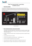
User’s manual to”Beril” ion electronic boiler control block
1. Basic technical parameters
Control block is functionally complete electronic device due to control electronic boiler ”Beril” in
accordance with received entered information (from sensors) and beforehand entered working conditions.
Control block is a monoblock connected with temperature sensors and it controls three-phase/one-phase
electronic boiler ”Beril”.
Image of control block panel.
2. Device plug-in, indication and controlled parameters
After switching on control block, loading and current firmware version displays on indicator’s screen:
Loading ...
Version: 1.0
Next after loading control block turns on working conditions and displays date and time:
17:45 10.01.2012
Indication consists (in accordance with control block panel image) of two-row symbol indicator on which
parameters (to select press appropriate key) selected by user and indicators next to keys display:
...
- temperature conditions,
- phase currents of electrodes,
- current date and time,
- consumed capacity,
Example: screen view if press
t1
key:
- currently measuring temperature on sensor t1=30°C,
Т1 – set temperature T1=35°C,
Δ
- set temperature offsets ΔT1=±10°C.
Note: All temperature conditions, phase currents of electrodes, current time and date are displayed in one
row. Consumed capacity - kWh and temperature condition - t3 are displayed in two rows.
Indication next to keys signifies as follows:
-
t1 – t4 :
turned off –
no sensor in system
green –
sensors are connected
(N.O. – if radio sensor is connected instead of t3)
-
red –
T- ΔТ˂ t ˂ T+ ΔТ
blinking red-
sensor loss
blinking orange -
T and ΔТ programming
L1 – L3: turned off –
green –
no voltage on a phase
no voltage supply on electrode
-
M:
red –
voltage is supplied on electrode
blinking red –
electrode operation’s failure mode
blinking orange-
failure current programming
turned off –
no voltage supply on a pump
green –
extended operation mode
red –
normal operation mode
blinking red –
dead short
blinking orange -
operation mode change
3. Control system and working algorithm
Control system consists of (in accordance with control block panel image):
Supply switch-on key (left on top),
4 keys to program operation modes (
- parameter input,
- increase,
- decrease,
- cancel),
4 keys to output + program temperatures (
....
Water pump operation mode selection key (
)
)
Electrodes current indication switch-on and failure current programming key (
Consumed electricity output key (
Output + time programming key (
)
)
)
After pressing any other key information displays on upper indicator’s row with previous information’s
offset to lower row.
Briefly press
key to view consumed electricity for current and previous months.
Example: 123.5 kWh for January 2012 :
kWh: 1.2012
123.45
Pass to previous month and otherwise use
and
.
Press and hold (more than for 5 seconds)
working period
Press
key to display total consumed electricity for all block’s
key to output empty row.
To entry programming mode (time and date input, T1-T3, ΔТ1- ΔТ4,Ω, T1.1-T2.1, ΔТ1.1- ΔТ2.1, A!, T2!)
press and hold appropriate key for ≥ 5 seconds until blinking orange indicator lights up.
Use
and
Press
key to confirm changed parameter and move to another one.
Use
keys to change current parameter.
key to exit without saving.
Note: If user didn’t leave programming mode (blinking orange), then after 60 seconds it automatically exits
without saving parameters.
4. Technical system parameters
Control block connects to one-phase or three-phase electrical grid with capacity 25 Ampere on a
phase at least.
One-phase or three-phase electric boiler ”Beril” connects to control block with current limit under 25
Ampere/50Ampere on a phase.
Water pump connects to control block with capacity from 10 to 100 W.
Two heat carrier’s temperature sensors (on boiler’s output – t1 and on input – t2) connect to control
block.
Possible control block connection to room (t3) and outdoors (t4) temperature sensors.
5. Nomenclature
t
- currently measuring temperature on sensor (°C),
A1/A2/A3
- phase currents on electrodes (A),
Т
– programmed temperature (°C),
Δ/ ΔТ
- programmed temperature offsets (°C),
Ω
-
T1.1/T2.1
-
ΔТ1.1/ ΔТ2.1
-
A!
- failure phase current on electrode (A),
T2!
-