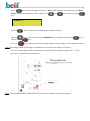
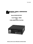
1
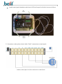
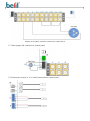
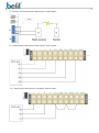
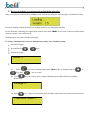
”Beril” ion electronic boiler’s control block
installation manual
1. Operation principles
Control panel is a functionally complete electronic device due to control electronic boiler ”Beril” in
accordance with received entered information (from sensors) and beforehand entered working conditions.
Control panel is a monoblock connected with temperature sensors and it controls three-phase/one-phase
electric boiler ”Beril”.
Control panel image
2. Basic technical parameters and structural scheme
In accordance with structural scheme below a control panel can be connected to one-phase or threephase electric current with capacity 25 Ampere at least on a phase, and control panel is compatible
with the following devices:
one-phase / three-phase electric boiler ”Beril” with limited current less than 25 Ampere/50 Ampere
on a phase;
water pump (M) with power 10 to 100 W;
two heat carrier temperature sensors (boiler output – t1 and boiler input – t2)
room (t3) and outdoor (t4) temperature sensors are optional;
wireless thermostat is optional to connect instead of wire temperature thermostat (t3).
optional connection to one-phase or three-phase boiler in one-phase operating mode.
Control panel structural scheme
3. Control block assembly and external device and sensors connection
3.1. Control panel is installed on a wall in a following way:
Take off front case of control panel. Top and bottom screws are positioned as follows:
Install control panel foundation with electric PCB on fireproof wall with 4 screws as follows:
3.2. One-phase or three-phase electric boiler ”Beril” connections to control panel:
Scheme of three-phase ion boiler connection to control block
Scheme of one-phase ion boiler connection to control block
3.3. Water pumps (M) connection to control panel:
3.4. Temperature sensors t1, t2, t3 and t4 connections to control panel:
3.5. Wireless room thermostat connections to control panel:
3.6. Control panel connections to three-phase electric panel:
3.6. Control panel connections to one-phase electric panel:
4. Indication, control system and controlled parameters
Indication consists of (in accordance with control panel image) two-row symbol indicator on which
parameters (to select press appropriate key) selected by user and indicators next to keys display:
...
- temperature modes,
- phase current on electrodes,
- date and time,
- consumed capacity,
- water pump control
- empty row output.
Example: screen view if press
key:
Symbols:
t1
- currently measuring temperature on sensor t1=30°C,
Т1 – set temperature T1=35°C,
Δ
- set temperature offsets ΔT1= ±10°C.
Indication next to keys signifies as follows:
- t1 – t4 :
turned off –
no sensor in system
green –
sensors are connected
(N.O. – if radio sensor is connected instead of t3)
red –
T- ΔТ < t < T+ ΔТ
(N.O. – if radio sensor is connected instead of t3)
blinking red-
sensor loss
T and ΔТ programming
blinking orange L1 – L3: turned off –
-
M:
no voltage on a phase
green –
no voltage supply on electrode
red –
voltage is supplied on electrode
blinking red –
electrode operation’s failure mode
blinking orange-
failure current programming
turned off –
no voltage supply on a pump
green –
extended operation mode (Pump mode: ext.)
red –
normal operation mode (Pump mode: norm.)
blinking red –
dead short; pump and heating L1 – L3 switch off.
Failure mode drops after supply is switched off.
blinking orange -
operation mode change
Control system consists of (in accordance with control panel image):
Supply switch-on key,
4 keys to program operation modes (
- parameter input,
- increase,
- decrease,
- cancel),
4 keys to output + program temperatures (
....
Water pump operation mode selection key (
)
)
Electrodes current indication switch-on and failure current programming key (
Consumed electricity output key (
Output + time programming key (
)
)
)
To entry programming mode (time and date input, t1-t4, A1-A3, M) press and hold appropriate key for ≥ 5
seconds until blinking orange indicator lights up.
Use
and
Press
key to confirm changed parameter and move to another one.
Use
keys to change current parameter.
key to exit without saving.
Note: If user didn’t leave programming mode (blinking orange), then after 60 seconds it automatically exits
without saving parameters.
5. Device switching on and operation algorithm selection
Once you switch on control block, loading screen and current firmware version display on indicator screen:
Next after loading control block sets on working mode by screening date and time.
For the first time switching on control block starts in first mode (Mode 1). For next switch-on control block
starts in a mode it was switched off.
Working mode sets with switching on supply.
To change working modes and reset manufacturer setups enter installator menu:
Switch off supply,
Press and hold
+
keys,
Switch on supply,
Mode ->
When on screen appears
4.1.
Press
key to enter working mode menu (Mode:1-4) , to change mode use
keys and
4.2. Press
or
key to accept.
key one time to enter voltage calibration point (describtion in installatio
instruction):
Voltage ->
4.3 Press
key 2 times to enter phase turn-off mode setup menu if maximal current increases.
Fault wire mode >
Press
key to enter working mode menu – Mode: All (all phases turn off at once) or Mode:
Single (only failure phase turns off), to choose use
and
keys and to accept use
key.
Reset ->
4.4 Press
key 3 times to enter manufacturer setups reset menu:
If press
key, on screen shows up title Reset all. To accept this action press
cancel it using
key.
4.5 Press
key or
key to enter previous menu point without saving settings (or exit installator menu).
Note: Discarding control block setups to manufacturer’s doesn’t erase memory of failures.
5. In case of three-phase boiler connection to one phase before turning on jumper J5.3 – J5.4 is
necessary to install as shown on picture:
Note: From installator menu is automatic exit by timer (one minute without pressing keys).
6. Control block working algorithms
Control block works in one of 4 selected conditions:
[Mode 1] – This mode uses temperatures from sensors t1 and t2.
1. Working in this mode ion boiler’s heating switches off if it exceeds T1+ ΔT1 or T2+ ΔT2
values.
2. Next sensor, through which was made a switch off, is controlled to estimate a moment of
boiler’s switch on.
3. Switch on starts when temperature decreases under T1- ΔT1 or T2- ΔT2.
Ion boiler’s programming temperatures range: 5°С≤ T1≤ 75°С and 5°С≤T2≤55°С (step 1°С)
Hysteresis temperatures range: 1°С ≤ΔT1≤10°С и 1°С≤ΔT2≤10°С (step 1°С)
Always do program T2<T1
Installations by default T1= 60°С and T2=40°С, ΔT1=03°С and ΔT2=02°С.
Installations by default T1.1=05°С and T2.1=05°С, ΔT1.1=02°С and ΔT2.1=02°С.
[Mode 2] – This mode uses temperatures from sensors t1, t2 и t3 (priority on t3).
1. Working in this mode ion boiler’s heating switches off if it exceeds T1+ ΔT1 or T2+
ΔT2 or T3+ ΔT3 values.
2. To estimate a moment of boiler’s switch on, a control is accomplished with temperature
parameter T3- ΔT3 or with sensor, through which was made a switch off.
3. Switch on starts when temperature decreased under programmed values T1- ΔT1 or T2ΔT2 or T3- ΔT3.
Programming temperatures range: 3.0°С≤ T3≤ 30.0°С (step 0.1°С)
Hysteresis temperatures range: 1°С ≤ΔT3≤5°С
Installations by default T3= 20.0°С and ΔT3=1.0°С.
[Mode 3] – This mode uses temperatures from sensors t1 and t2 and t4.
1. Working in this mode ion boiler’s heating switches off if it exceeds T1+ ΔT1 or T2+
ΔT2 values.
2. Next sensor, through which was made switch off, is controlled to estimate a moment of
boiler’s switch on.
3. Switch on starts when temperature decreases under programmed values T1- ΔT1 orT2ΔT2.
4. If change t4= -10°С, then programmed value T2 keeps constant.
5. Every time decreasing t4 by ΔT4 value do charge up Ω value to T2.
6. Every time increasing t4 value by ΔT4 do subtract Ω value from T2.
Hysteresis temperatures range: 1°С ≤ΔT4≤20°С (step 1°С)
Ω range : 1°С ≤ Ω ≤5°С (step 1°С)
Installations by default ΔT4= 10°С or Ω =03°С
[Mode 4] – This mode uses temperatures from sensors t1 and t2 and t3 and t4.
This mode merges all 3 previous modes
7. Control block failure working conditions
Press button
and control panel screen shows following text:
In this case water pump indicator lamp light is red, what means pump working mode is normal (Pump
mode: norm.).
T pump: 0oC - programmed temperature to turn off water pump; this parameter follows t1
measurement in extended working mode at switched off heating (compatible only with Mode 2 and
Mode 4).
Press
button for at least 5 seconds until orange indication lamp lights up to program working modes.
Press
button to turn on extended working mode (Pump mode: ext.). Press
back to normal working mode (Pump mode: norm.).
Press
button to save selected mode and to program water pump turning off temperature.
Programmed temperature range: 0°С ≤T pump ≤ T2°С (step 1°С).
button to switch
8. Control block failure working conditions
Current exceeds more than A! on any phase (if exceed is on one phase, then one phase switches off –
Mode: Single or all phases turn off – Mode: All) and an appropriate blinking red indicator on
control panel and indication (L1 or/and L2 or/and L3) turns on.
Temperature is controlled from sensor t2.
If t2 decreases under T! , then failure indication works and working mode (heating) turn on.
Programming temperature range: 3°С≤T!≤20°С (step 1°С)
Installations by default T!=05°С
Programming current range: 10A≤A!≤60AС (step 1A)
Installations by default A!=18A
After entering failure mode the system is waiting until temperature drops under T2- ΔT2, so then a
standard mode turns on.
9. Incident log
Memory of failures is divided into 2 parts: current incident log and total incident log,
Capacity of every part is max 64 incidents,
Cyclic memory fill – since memory’s buffer is completed, old values get erased by new ones,
Press together
+
keys to enter current incident log.
Press together
+
keys to enter total incident log.
Use
or
Press together
keys to move in incident log.
+
or
+
keys to move together 10 incidents.
Press together
+
+
keys to delete current incident log.
Press together
+
+
keys to delete current incident log.
Phrase ”No more records” will display if you have came to the end of incident log list. Exit from viewing
mode by pressing
.
Note: There is no automatic exit by timer from incident log mode.
Failure incident list in current incident log part displayed on indicator:
Fault A1 Val =.... (current value on phase L1)
Fault A2 Val =.... (current value on phase L2)
Fault A3 Val =.... current value on phase L3)
Failure incident list in total incident log part displayed on indicator:
Fault T1 Val =.... (temperature value, if ≥T1 + ΔT1 + 3°C)
Fault T2 Val =.... (temperature value, if ≥T2 + ΔT2 + 3°C)
Sensor lost: 1 ( lost connection with temperature sensor t1)
Sensor lost: 2 (lost connection with temperature sensor t2)
Sensor lost: 3 (lost connection with temperature sensor t3)
Sensor lost: 4 (lost connection with temperature sensor t4)
Sensor rest: 1 ( resumed lost connection with temperature sensor t1)
Sensor rest: 2 (resumed lost connection with temperature sensor t2)
Sensor rest: 3 (resumed lost connection with temperature sensor t3)
Sensor rest: 4 (resumed lost connection with temperature sensor t4)
Pump fault A =.... (pump failure’s current value).
10.Technical system parameters
Control block connects to one-phase or three-phase electrical grid with capacity 25 Ampere on a
phase at least.
One-phase or three-phase electric boiler ”Beril” connects to control block with current limit under 25
Ampere/50Ampere on a phase.
Water pump connects to control block with capacity from 10 to 100 W.
Two heat carrier’s temperature sensors (on boiler’s output – t1 and on input – t2) connect to control
block.
Possible control block connection to room (t3) and outdoors (t4) temperature sensors.
11. Nomenclature
t
- currently measuring temperature on sensor (°C),
A1/A2/A3
- phase currents on electrodes (A),
Т
- programmed temperature (°C),
Δ/ ΔТ
- programmed temperature offsets (°C),
Ω
- programmed temperature correction accordingly to another temperature
sensor measurements (°C),
T1.1/T2.1
- alternative programmed temperature (°C),
ΔТ1.1/ ΔТ2.1
-alternative programmed temperature offsets (°C),
A!
- failure phase current on electrode (A),
T!
- failure incident programmed temperature (°C).
T pumps
- programmed temperature to turn off water pump (°C).
SIA ”BERIL”
Latvija, Ieriķu iela 48 Rīga, LV-1084,
tel.: +37167501262,
mob.tel.: +37126605309
Ltd. “BERIL”, Ieriku street 48, Riga, LV-1084, Latvia, ph.: +37167501262
Mob.ph.: +37126605309