1
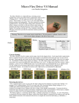
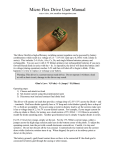
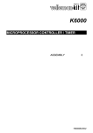
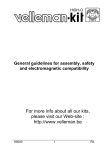
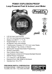
Micro Flex Drive V5 Manual
©2009 Nautilus
Integration
The Micro FlexDrive is a high-efficiency switching current
regulator that can be powered by battery combinations which result in
a Voltage of 2.0 – 5.5V DC (and up to 6.4VDC with a diode in
series). This includes 2-4 AAAs, AAs, Cs, Ds, and single lithium
batteries primary and rechargeable. The driver operates as a current
regulated source, varying the output voltage above and below the
battery voltage as necessary to meet the current output setting. In
operation, the driver will drain the power source until its voltage
reaches 2.0V and then will shut off. This, combined with the high
efficiency of the driver provides the maximum runtime possible for
portable lasers.
Warning: This driver is a current source mode driver. Do not operate it without a load or with a
short circuit output, damage to the driver may result.
- Battery
Diode -
Parameter
Input Voltage
Output Voltage
Output Current
Conversion Efficiency
Regulation Ripple (4-100kHz)
+
+
Specification Unit
2.0-5.5
2.0-5.5
0.065-1.5
80-95
< 1%
V
V
A
%
%
(Photo of FlexDrive V4. Contacts not different from V5.)
Current Setting:
The Micro FlexDrive has five output current ranges, listed in the diagram below. Each range listed in approximate,
there is variation from unit to unit so test the closest range to your desired current and work your way up or down
the scale. Removing the end resistor has the effect of decreasing the output current slightly when you are in ranges
2-4. The default 65-100mA range requires no changes. The other ranges require solder jumpers as shown. To
adjust and set the diver current, a load is required. A series of 3 or 4 1N4001 diodes and a 1 to 0.2 ohm resistor is
recommended for use as a dummy load. Use the Voltage across the dummy load resistor to determine current.
Output current is adjusted via the potentiometer trimmer. An insulated screwdriver and a light touch are
recommended for adjustment.
65-100mA
100-412mA
412mA-1.1A+
500mA-1.5A+
(Photos of FlexDrive V4. Contacts not different from V5.)
Powering the driver:
If 6V or greater battery source is to be used, the input voltage must be dropped to no greater than 5.8VDC. For
example, if two Lithium primary CR123As are used, each with a maximum surface charge voltage of 3.2V, a
1N4000 series diode should be placed in series with the driver power input.
The FlexDrive V5 contains built-in battery reverse polarity protection.
The battery negative (-) connection and the diode – (cathode) connections are continuous. As such, if the battery –
is connected to the laser casing at the battery, and the laser diode cathode is connected to the casing as well, only the
diode cathode lead needs to be connected to the driver to complete the circuit for both battery (-) and diode (-)
connections.
Warning!
These wiring diagrams assume a laser
output power below 5mW. If your
laser product optical output is greater
than 5mW, you must adhere to CDRH
regulations which may require
additional wiring including interlocks.
Maximum current limitations for full input voltage range:
The Micro FlexDrive is built using the latest technology and is designed to have a very wide range of output
currents and voltages. However not every combination of input voltage, output voltage and output current is
useable. For example a 5V load cannot be powered at 1 Amp with an input voltage ov 2.0V. Here are the
recommended output current ranges for the full 2.0-5.5V input range per output voltage:
75-400mA buck/boost 5V out
75-800mA buck/boost 3V out
75mA-1.5A 2.0V out with 4.2-3.0V in (li-ion)
A good rule of thumb is that: (Vout (Volts) * Iout (Amps) ) / Vin (Volts) < 1.2
For powering high current (>500mA) 1.8V diodes, a series shottky rectifier is required so that the output voltage is
2.2V or greater. When powering loads above 500 mA and below 3V, a heatsink on the black 5-pin chip on the back
of the driver is required. An electrically insulating thermal epoxy to the heatsink or casing is recommended.
Driver Fitment:
The Micro FlexDrive can easily fit in most laser cases including AAA powered lasers and even inside the ‘Aixiz’
modules. Care should be taken not to allow the driver to contact conductive sides of the laser casing. In the event
that the casing does come close to the driver, you can wrap the driver in a single layer of insulating electrical tape to
prevent shorts to the casing.
12mm
9 mm
(Photo of FlexDrive V4. Dimensions not different from V5.)