1
Micro Flex Drive User Manual
Andrew Kibler, 2008; nautilus-integration.com
The Micro FlexDrive high-efficiency switching current regulator can be powered by battery
combinations which result in a voltage of 2.5 – 5.5V DC (and up to 6.2VDC with a diode in
series). This includes 2-4 AAAs, AAs, Cs, Ds, and single lithium batteries primary and
rechargeable. You can use it with 2 3V lithium primary (not rechargeable) batteries if you put a
forward biased diode in series with the + In. In operation, the driver will drain the battery until
its voltage (during operation) reaches 2.4V and then will shut off or begin to blink. If this
happens it is time to replace or recharge your battery.
Warning: This driver is a current source mode driver. Do not operate it without a load
or with a short circuit, damage to the driver may result.
Ohm’s Law: V(Volts) = I (Amps) * R (Ohms)
Operating steps:
1) Choose and attach test load
2) Set desired current using the potentiometer (pot)
3) Disconnect test load and connect final diode load
The driver will operate on loads that provide a voltage drop of 2.5V-5.5V across the Diode + and
– terminals. Red laser diodes typically have a 3V drop and violet diodes typically have a drop of
5V, so both are acceptable. If you are using a resistive dummy load to set the current, make sure
it has a voltage drop of 2.5 to 5V at your desired current. For example, if your target current for
a blu-ray diode is 38mA, for testing, use a load resistor of 5V/.038A = 131 Ohms to accurately
model the diode operating point. Another good dummy load is simply 4 regular diodes in series.
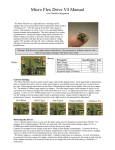
For 91-151mA (low) range, simply set the pot. For the 175-700mA current range, solder a
jumper across the high range selector pads seen in the bottom corner of the photo. To adjust the
operating current, turn the pot with a small electronics screwdriver. Careful, it is tiny and
sensitive. Do not turn the pot all the way around. Counterclockwise rotation turns the current
down while clockwise rotation turns it up. When shipped, the pot is at its midway point as
shown in the picture.
The battery ground (-;gnd) board contact does not have to be connected IF the diode gnd is
connected to battery gnd through the casing or other means.
For use with 6V battery supplies (4x 1.5V or 2x 3V primary cr123 cells):
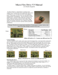
The FlexDrive may be used with 6V battery combinations, but a voltage drop diode must be
installed on the driver power input. Install according to the figure:
+ batt connects here:
The small box is the high range solder jumper. The vertical bars are the cut lines for fitting in an aixiz
module. For fitting in an aixiz module, the tiny black box in the upper right corner can be removed.