1
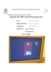
FPGA PAINT
Design of Embedded Systems, Advanced Course
Faculty of Engineering (LTH)
Lund University, Sweden
November 30th, 2010
Course Responsible: Flavius Gruian
Viktor Do ([email protected])
Zhang Dalong ([email protected])
Kazi Asifuzzaman ([email protected])
Abstract
This report summarizes the project ‘FPGA PAINT’ where we implemented paint function using
Digilent Nexys 2 FPGA Board as the requirement of the ‘Design of Embedded Systems, Advanced
Course’. The report describes the implementation of the project with hardware description
language (VHDL) and software programming language (C) using the Xilinx Platform Studio (XPS).
It also includes the overall hardware and software overview and design details.
FPGA Paint – Kazi Asifuzzaman, Zhang Dalong, Viktor Do
2
Table of Contents
1
Introduction ............................................................................................................................. 4
2
Hardware ................................................................................................................................. 4
3
2.1
VGA Display...................................................................................................................... 5
2.2
PS/2 Mouse ...................................................................................................................... 5
2.3
Interrupt Controller ......................................................................................................... 5
Software ................................................................................................................................... 6
3.1
The program .................................................................................................................... 6
3.2
Mouse Data Communication ........................................................................................... 7
3.3
BMP to COE converter ..................................................................................................... 8
4
Design Summary ...................................................................................................................... 9
5
Problems and Solutions ......................................................................................................... 11
5.1
PS/2 mouse control........................................................................................................ 11
5.2
DMA transaction timing................................................................................................. 11
5.2.1
The problem and the solution ............................................................................... 11
5.2.2
Further improvement ............................................................................................ 12
6
User manual ........................................................................................................................... 13
7
Conclusion.............................................................................................................................. 14
8
References ............................................................................................................................. 15
FPGA Paint – Kazi Asifuzzaman, Zhang Dalong, Viktor Do
3
1 Introduction
The idea of the project is to implement a paint program in a FPGA board (Digilent Nexys2). The
program has a PS/2 mouse as an input device and a VGA monitor as an output device. User can
draw lines, color a picture or both and can follow it on the VGA screen.
We have used VHDL for the hardware design and C for the software development. Most of the
logic, paint tools and interface have been implemented in software. The main goal of the project
is to have a clear understanding of the total cycle of an embedded system design process
starting from specification to implementation.
2 Hardware
The project was implemented based on Digilent Nexys2 board together with a CRT monitor and
a PS/2 mouse. The hardware consists of Micro Blaze, PLB bus, BRAM, VGA controller, DMA,
Interrupt controller, SDRAM and PS/2 interface, as describe in Figure 1. The block diagram
extracted from Xilinx EDK is pasted in Figure 5. This section will discuss the major components.
Figure 1: Hardware architecture
FPGA Paint – Kazi Asifuzzaman, Zhang Dalong, Viktor Do
4
2.1 VGA Display
FPGA Paint supports the resolution of 640p * 480p at 60 Hz of frame frequency, and 4-bit color
depth (16 colors). VGA display consists of the following parts:
•
•
•
•
•
•
VGA controller
VGA signal generator
VGA pixel generator
Row buffer implemented from BRAM
Frame buffer implemented from SDRAM
DMA [4]
VGA Controller consists of Signal generator which generates VGA timing signals, refer to, and
Pixel generator which fetches the data of each pixel from Row buffer and output it. Since the onchip BRAM is too small to support 640p * 480p image, SDRAM is used as a frame buffer. BRAM
only needs to store the data of a single row, while DMA is responsible for the data transaction
from SDRAM to BRAM. VGA controller generates a horizontal interrupt after it displays each row;
and the micro-processor pause the current process and jumps into the interrupt handler where
the DMA transaction of the data in the next row takes place. Vertical interrupts are required by
DMA control to locate the position of each row.
The VGA driver provides an interface for the user to manipulate the data of the pixels on the
screen.
2.2 PS/2 Mouse
Xilinx PS/2 interface IP is utilized for mouse control in hardware [5]. It works in interrupt mode,
and the output data are handled outside of interrupt handler for performance reasons, refer to
Section for details.
2.3 Interrupt Controller
The interrupt controller is customized from Xilinx Intc IP [3] in EDK. It takes 3 interrupts listed
below in the order of priorities (high to low):
•
•
•
PS/2 interrupt
Vertical interrupt from VGA
Horizontal interrupt from VGA
FPGA Paint – Kazi Asifuzzaman, Zhang Dalong, Viktor Do
5
3 Software
3.1 The program
The software runs in an infinite while loop and takes cares of the data that is generated by the
mouse interrupt which the software logic handles.
The mouse logic makes sure that the mouse stays inside the screen boundaries and it also
checks if the user is clicking the left button or holding it down. As long as the left button is held
down a straight line algorithm is used to draw a line from the last position of the mouse to the
new position.
The program also displays the mouse cursor on the screen. This is done by taking backup of the
pixel color information underneath the cursor and rewrites the information when the mouse
moves in order to not destroy the underlying picture.
Here is a simple flow chart over the paint logic.
Figure 2: Software Data Flow
FPGA Paint – Kazi Asifuzzaman, Zhang Dalong, Viktor Do
6
3.2 Mouse Data Communication
The data is sent trough the ps/2 interface every time the mouse generates an interrupt. In order
to make the interrupt as fast as possible no data is processed inside the interrupt. The 3 bytes of
raw data is instead given to the logic of the paint program. The only thing the mouse interrupt
driver does is set a flag which tells the paint logic that there is some new information from the
mouse to process.
The three 8 bit data fields contain information about the action and movement from the mouse
according to the following table.
Figure 3: Data of Mouse
The ps/2 mouse uses a relative coordinate system where moving the mouse to the right gives a
positive X value while moving to the left gives a negative value. The Y position is similar as
moving the mouse up gives a positive and moving down gives a negative value. Because it uses a
relative coordinate system we have to have a boundary check in the paint logic or the mouse
will disappear outside of the screen. One thing worth mentioning is that the two directions are
represented in two´s complement arithmetic which needs to be converted into decimal value in
order for it to be used with the paint logic.
For the mouse buttons we check the L and R bit in the status byte. A ´1´ represents button
pressed down.
FPGA Paint – Kazi Asifuzzaman, Zhang Dalong, Viktor Do
7
3.3 BMP to COE converter
This is not part of the project but only a tool that was used to test VGA controller with BRAM. It
can convert a 24-bit bmp file to a coe file. We can use it to pre-define BRAM with real pictures,
as shown in Figure 4. The source file of it was packed together with the project source.
Some limitations of the current version:
•
•
•
Only supports 24-bit to 8-bit color conversion.
Only output 32-bit HEX data per line (4 pixels per line) in coe file.
Only runs in MS Windows system.
These can easily be further improved if needed.
Figure 4
FPGA Paint – Kazi Asifuzzaman, Zhang Dalong, Viktor Do
8
4 Design Summary
The design was implemented by Xilinx EDK 12.2. Below is the block diagram generated by EDK.
Figure 5: Block Diagram
FPGA Paint – Kazi Asifuzzaman, Zhang Dalong, Viktor Do
9
The design summary is listed as below.
Logic Utilization
Number of Slice Flip Flops
Number of 4 input LUTs
Number of occupied Slices
Total Number of 4 input LUTs
Number of bonded IOBs
Number of RAMB16s
Number of BUFGMUXs
Number of DCMs
Number of BSCANs
Number of MULT18X18SIOs
Average Fanout of Non-Clock Nets
Used
3,123 out of 17,344
4,599 out of 17,344
3,500 out of 8,672
4,770 out of 17,344
59 out of 250
12 out of 28
3 out of 24
1 out of 8
1 out of 1
3 out of 28
3.48
Utilization
18%
26%
40%
27%
23%
42%
12%
12%
100%
10%
FPGA Paint – Kazi Asifuzzaman, Zhang Dalong, Viktor Do
10
5 Problems and Solutions
Problems were encountered in the development process, the solutions of which are sometimes
not obvious from only using Google. Here we only describe the major ones.
5.1 PS/2 mouse control
We had several options when we came developing the mouse controller:
• Adapt the mouse controller provided by Digilent, which is available in their website
• Adapt the PS/2 interface IP from Xilinx
• Develop from scratch
After investigation we realized that the mouse controller from Digilent returns the absolute
position of the mouse curser. But relative position is required by the software in our project.
Then we integrated the PS/2 interface IP and had weird thing happened. Since we had
experience in working with PS/2 keyboard from existing projects, we tested the project using
keyboard first and it was working fine with keyboard. However when we unplug the keyboard
and plug in a mouse, the PS/2 did not generate any interrupts when the mouse was moving or
clicked. The problem was that you can´t unplug the keyboard and plug in the mouse, reset the
board and upload the bit file into the board. It needs to be turned off and on again with the
mouse plugged in. We couldn’t find the reason for that due to time constrains, it is most likely
because of some non-volatile components in the PS/2 interface module.
When receiving data from the mouse interrupt, we encountered a problem that it took too long
time. This interfered with our VGA interrupt which made the screen very shaky and impossible
to have a good painting experience. The problem was that we put all the data handling in the
interrupt. Following the suggestion from Flavius, this problem was solved with moving all the
receiving of the data and computations into the paint logic. All the interrupt should do is setting
a global variable telling the paint logic to process the incoming mouse data.
5.2 DMA transaction timing
5.2.1 The problem and the solution
The greatest difficulty we had was about the DMA timing. The basic VGA component, which was
working with on-chip BRAM, was implemented smoothly in the beginning phase of the project.
It could display a 160p * 120p predefined image on screen, Figure 4. Since the size of BRAM was
too small to hold a 640p * 480p image, the on board SDRAM has to be used for that as the VGA
buffer. Also BRAM was used as the line buffer. The details are described in Section 2.1.
Unfortunately the time of DMA transaction from SDRAM to BRAM was around 1600 clock cycles
when 1 byte color depth (256 colors) was utilized. This was too much to be acceptable in that
(800 – 640) *2 = 320 clock cycles is the maximum available between each scan line. Therefore
we had to decrease the color depth to 4-bit (16 colors) to meet the timing constrain. This was
probably also the reason that “FPGA Frame” from last year did not display correctly, refer to the
Page 9 in their report.
FPGA Paint – Kazi Asifuzzaman, Zhang Dalong, Viktor Do
11
5.2.2 Further improvement
Of course the VGA buffer timing control was based on interrupts and DMA transaction. This
means that VGA controller generates an interrupt after it displays each row; and the microprocessor pause the current process and jumps into the interrupt handler where the DMA
transaction of the data in the next row takes place. In theory 4 bytes can be transferred in burst
mode in each clock cycle in 32-bit bus, which means 1280 bytes (in 320 clock cycles) is the
maximum of data for each transaction. Of course several clock cycles are required to setup the
DMA transaction and so on. Thus the resolution of 640p * 480p with 1 byte color depth per pixel
could be realized in theory. Apparently burst mode didn’t take place in our DMA transaction.
The reason is still under investigation. Also the transaction can also be carried on by only
hardware without interrupt controlling and DMA involved. The main benefit of it is that the load
of micro-process would be significantly decreased. Please look into xps_tft, a build-in IP from
Xilinx for technical details. Unfortunately this IP does not work in burst mode on Nexys2 either.
FPGA Paint – Kazi Asifuzzaman, Zhang Dalong, Viktor Do
12
6 User manual
•
•
•
•
To start the program, upload the bit-file to the FPGA board.
To paint something in the screen you can left click the mouse button in the drawing area.
If you hold the left button down it will draw a continuous line. To change color you can
either right click which will choose a random color or choose the color in the bottom of
the menu bar.
The first three buttons on the menu bar selects brush size from smallest to biggest. The
fourth button is the eraser tool. You can also change size of the eraser after picking it.
The fifth button, the dark square will reset the drawing area.
FPGA Paint – Kazi Asifuzzaman, Zhang Dalong, Viktor Do
13
7 Conclusion
The project offered us a great chance to have practical experience on embedded system design
and achieved working level expertise on embedded systems and related areas. We had to use
hardware components as well as software parts and integrate between them and throughout
the project we had to study extensively on related matters while working on the project. That
greatly improved our skills of approaching towards a problem and solving it. We gained a lot of
knowledge from related things while working that might not be connected with the current
project but contributed a lot for our future works in this area.
One important lesson is that making software for a PC and porting it to an embedded system is
not easy sometimes. The software behaves very different on the two systems and you have to
take a lot of constraints into consideration. Debugging an embedded system requires a lot of
patience and is very time consuming and it can be very frustrating when you encounter problem
but it was very satisfying and rewarding both mentally and educationally to manage building
something from scratch.
FPGA Paint – Kazi Asifuzzaman, Zhang Dalong, Viktor Do
14
8 References
[1]. Video Graphics Array (VGA), Wikipedia.
[2]. Digilent Nexys2 board reference documents.
[3]. XPS interrupt controller datasheet.
[4]. XPS Central DMA Controller datasheet.
[5]. XPS PS/2 controller datasheet.
[6]. XPS TFT controller datasheet.
[7]. Report of FPGA Frame, link.
FPGA Paint – Kazi Asifuzzaman, Zhang Dalong, Viktor Do
15