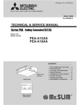
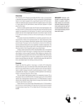
1
GTR mini Gearmotors
1/50 Hp ■ 1/30 Hp ■ 1/20 Hp ■ 1/15 Hp ■ 1/10 Hp ■ 1/6 Hp
Instruction Manual
G-Type
H-Type
F2 Series
G-Type・Water-resistant
F2 Series・Water-resistant
H-Type・Water-resistant
For Safe Operation
●The Gearmotor should be operated by a skilled and qualified person. The contents
of this Instruction Manual should be carefully read and understood before operating
this product.
●This Instruction Manual should be accessible to the person who operates this
product.
●This Instruction Manual should be kept in a convenient place for the operator's
easy reference.
Address
TEL
FAX
E-MAIL
WEB
Brother International Corporation
100 Somerset Corporate Blvd, Bridgewater, NJ 08807
866-523-6283
908-575-3743
[email protected]
www.brother.com
Thank you for purchasing our product.
Potential injuries and/or damage caused by mishandling equipment are classified into two
categories, "Danger" and "Caution". The definitions of the classifications are given below
with the corresponding graphic symbols.
Danger
Caution
Mishandling the equipment may result in a dangerous
situation and may lead to serious or fatal injury to personnel.
Mishandling the equipment may result in a dangerous
situation and may lead to medium to light injury or damage
to the equipment.
Please be aware that even items marked with "CAUTION" may cause fatal accidents.
Therefore, it is important to follow the instruction for every item described.
Danger
●Use an explosion-proof motor when any explosive or flammable gases are present.
Failure to observe this warning may cause explosion, spark, fire, electric shock,
physical injury, and/or damage to the equipment.
●People in charge of transportation, installation, wiring, operation, maintenance, and
inspection of the equipment should have sufficient knowledge and technical skill to
install electrical and mechanical products. Failure to observe this warning may
cause explosion, spark, fire, electric shock, physical injury, and/or damage to the
equipment.
●Do not repair or wire the equipment with the electric power on. Cut the power
before working on this product. Failure to observe this warning may cause electric
shock.
●If the equipment incorporating this gearmotor is used in a system for human
transport, furnish it with sufficient protective devices for safety and follow any and
all local or national codes. Failure to observe this warning may cause physical
injury, death and/or damage to the equipment.
●If the equipment is to be used to drive an elevator, be sure to furnish it with safety
devices to prevent the elevator from accidentally falling. Failure to observe this
warning may cause physical injury and/or damage to the equipment.
●Be sure not to get water or oil/grease into the brake unit. Failure to observe this
warning may cause brake failure by decreasing brake holding torque.
2
Caution
●Do not use this gearmotor under conditions other than specified on the nameplate
or product specifications. Failure to observe this warning may cause electric shock,
physical injury and/or damage to the equipment.
●Do not insert your fingers or any other object into the terminal box, lead wire exit,
fan cover, or any other aperture of the gearmotor. Failure to observe this warning
may result in electric shock, physical injury, fire and/or damage to the equipment.
●Do not use a damaged gearmotor. Failure to observe this warning may result in
physical injury and/or fire.
●Do not remove the nameplate.
●The manufacturer will not warrant and will not be responsible for any product
modified or repaired by the user.
1
2
3
4
5
6
7
Contents
Check at Unpacking ............ P.3
Transportation .................... P.4
Storage ............................... P.4
Installation ......................... P.5
Connecting With Other Equipment ..... P.6
Direction of Rotation .......... P.8
Wiring ................................. P.9
8
9
10
11
12
13
Operation .......................... P.18
Inspection/Adjustment ..... P.20
Troubleshooting ............... P.24
Disposal ............................ P.25
UL/CSA Information .......... P.26
Standard Terms and Conditions of Sale .. P.27
1 Check at Unpacking
When unpacking the carton, please check the following items. If you have any problems
or questions, please contact the dealer from which the product was purchased or Brother
International Corp sales office.
Caution
Check whether the product is the product you ordered. Installing the wrong
gearmotor on your equipment may cause physical injury and/or damage to the
equipment.
(1) The ordered products and the contents indicated on the nameplate are correct.
(Type, Reduction Ratio, RPM, Horsepower or Watts, Voltage, Frequency, etc.)
(2) No accidental damage to the product during transportation has occurred.
(3) Screws or nuts are not loose.
(4) In case of a brake equipped gearmotor, be sure the rectifier is enclosed.
(5) In case of a single-phase motor be sure the capacitor is enclosed.
(6) In case of F2 series hollow bore/shaft mount type be sure the bore safety cap is
enclosed.
3
2 Transportation
Danger
●When a product is lifted up for transportation or installation use care. Products are
heavy and may be damaged and/or cause serious injury if they are dropped.
Caution
●Be careful when transporting products. Avoid dropping them.
●Before lifting a gearmotor, be sure to confirm the weight using the packing box or
the product catalog.
●Do not lift a gearmotor that is heavier than the specifications the mechanical lift
allows. Failure to observe this warning may cause physical injury and/or damage to
the equipment.
3 Storage
●Strage Location
(1)If the gearmotor or reducer will be stored for more than 6 months, store it indoors in
a well ventilated, dry area that is free from direct sunlight, excessive temperature
change, excessive humidity, dust, or corrosive gas.
(2)Do not store the gearmotor or reducer directly on the ground.
(3)Bearings may be damaged by fretting corrosion caused by vibration during storage.
Store the products in a location free from vibration.
●Strage Procedures
(1)To avoid oxidation on the bearings, run the gearmotor or reducer every 6 months
and check for smooth rotation and abnormal noise.
(2)Measure the insulation resistance of the motor using a 500V megger. The resistance should exceed 1MOhm.
(3)Apply anti-corrosive treatment every 6 months to any machined or unpainted surfaces such as the output shaft, pilot, or mounting flange.
●Operation After Extended Storage
(1)Prior to operation after extended storage check the motor insulation resistance using a 500V megger. It should exceed 1 MOhm.
(2)Check for any abnormal noise, vibration, or temperature rise upon initial starting of
the motor.
(3)If the gearmotor has a brake, be sure the brake functions properly prior to applying
an external load to the gearmotor.
4
4 Installation
Proper installation of a product will ensure reliable service and maximum life.
Caution
●Do not place any flammable object near the gearmotor. Failure to observe this warning
may cause fire.
●Do not allow interference with the ventilation of the gearmotor. Be sure to observe the
spacing requirements for adequate air flow around the gearmotor. In the case of a fan
cooled model, do not block the vent holes on the fan cover. Failure to observe this
warning may result in abnormal overheating and/or injury or fire.
●Do not step on a gearmotor. Do not use a gearmotor as a grip to hoist yourself onto a
machine. Failure to observe this warning may cause physical injury.
●Do not touch the edge of the shaft of the gearmotor or the key groove in the bore with
your bare hands. Failure to observe this warning may cause physical injury.
●Food machine regulations may prohibit the possibility of oil or grease getting into the
food area. If this is the case, please use a drip pan to prevent lubrication from getting
into the food area. Alternatively, please request that appropriate food grade lubricants
are applied.
●Leaking oil may cause products to fail.
●There is possibility scatter the wear debris or iron powders. In case of installing to
equipment which will have any issue due to contamination of foreign substance such as
food equipment, please install preventive equipment. This could harm the products.
●Vibration resulting from improper installation of the gearmotor or from other sources
should be under 0.5G.
●In the hot and humid environment, when ambient temperature changes suddenly,
internal condensation may occur in the terminal box. Especially, in the ocean transport
of the machine by vessel, condensation may occur, therefore, pay careful attention to
the transport atmosphere. Internal condensation is a phenomenon that in the hot and
humid environment, if temperature suddenly drops from high to low, or if a reducer is
suddenly moved from low-temperature place to hot and humid place, steam
condensation occurs and the droplet land on the terminal.
●In the low temperature of below 0℃, pay careful attention to the freezing. The droplets
land on the terminal by condensation or by abnormally high humidity atmospheres, and
when temperature drops below freezing point, the droplets become ice. This is what we
call “Freezing”. You must note that there is a danger of electrification caused by the
short circuit between terminals by freezing.
(1)Proper location for installation
Ambient Temperature: −10℃ to 40℃ (14°to 104°F)
Ambient Humidity: 85% max.
Altitude: Sea level to 3280 feet (1,000 meter) max.
Environment:
[Standard Type]: Well ventilated free from corrosive gas,
explosive gas, vapor and/or dust.
[IP-65 Type]: Well ventilated, free from corrosive gas, explosive gas, or vapor.
Operation submersed in water or subjected to high-hydrostatic pressure
jets of water is not permitted.
Installation Location: Indoors
5
(2)Direction of Installation
This product can be installed in any direction and any angle due to a grease lubrication
system.
(3)Method for Installation
①Attaching the mounting foot or flange
Secure the product with four bolts on a flat and machined surface free from vibration.
(Roughness of the surface should be less than 0.3mm.)
②Attaching the hollow bore/shaft mount unit to a shaft.
●The shaft should be able to support the gearmotor’ s weight.
(Forces other than turning or reactive force should not be imposed on the torque
arm.)
●In case of frequent start/stop or frequent forward/reverse applications tighten the
torque arm with bolts to keep the locking hole secure.
Tightenting Torque for Torque Arm
Fixing Hole
Metric (mm)
Metric Bolt
Size
Tightening
Torque (N-m)
Fixing Hole
Inch (in)
Inch Bolt
Size
Tightening
Torque (in-lb)
6.5
8.5
11
13
15
18
M6
M8
M10
M12
M14
M16
4.9
13
25
44
69
108
0.25
0.33
0.43
0.51
0.59
0.71
1/4-20
5/16-18
3/8-16
7/16-14
7/16-14
5/8-11
43
115
220
390
390
955
5 Connecting With Other Equipment
Caution
●When connecting the gearmotor to the load with a chain or belt, make sure of the
shafts parallel alignment is precise. Make sure the belt/chain tension is properly
adjusted and pulleys or sprockets are parallel.
●When direct coupling, make sure the concentric alignment of shafts is precise.
●Before operation, make sure the set screws for the sprockets, pulleys or coupling
are securely tightened. Failure to observe this warning may cause serious injury
and/or damage to the equipment.
●Safety guards should be furnished around rotating parts and securely in place
before starting the equipment.
●Do not over tension chain or belts. Damage to the gearmotor may occur due to
excessive overhung load.
●Avoid excessively rigid direct couplings as damage may occur to the bearings due
to high overhung load.
6
1
Direct Connection
The center of the shaft of both machines should be aligned concentrically precise.
The displacements δ and θ should be minimized as much as possible.
Please refer to the manufacturer of the couplings allowance for misalignment.
2
Attaching Chains, V-Belts, Gears, etc.
3
F2 Series Hollow Bore/Shaft Mount : Attaching and Removing a Shaft
(1) Make sure the shaft of the gearmotor and the driven shaft of the equipment are
parallel.
(2) Chains, V-Belts, couplings, or gears must be perpendicular to the center of the shaft.
(3) Excessive tensioning of a V-belt or chain may result in damage to the bearings of the
gearmotor or driven shaft.
(4) If the chain or V-belt is installed loosely, shock load may occur when the driven shaft
starts. This can result in damage to the reducer or the equipment. Adjust the tension
of the chain properly.
①Attaching the Shaft
●Apply anti-seizing agent such as
molybdenum disulfide on the driven
shaft.
●If the fit is tight, tap the edge of the
hollow drive shaft with wooden
hammer.
●If strong impact or heavy radial
loading is expected, the fit should be
tighter.
●In general, a loose fit is
recommended for the fit tolerance of
the driven shaft.
②Removing the Shaft
Note: To allow smooth removal, design
the driven shaft to stop short of the
snap ring groove.
7
③Securing the Shaft
If the driven shaft has a shoulder
If the driven shaft does not have a
shoulder
Note: Firmly secure the driven shaft to
the bore.
●Specifications for the fixing parts of driven shaft
Bolt Size
Dimension of Spacer
Metric
Inch
O.D.
I.D.
Width
Type of
Snap Ring
F2S-12
M5
1/4-20
0.48
0.24
0.12
Nominal 1/2
F2S-15
M6
1/4-20
0.61
0.28
0.12
Nominal 5/8
6 Direction of Rotation
Caution
Before coupling with the other machine check the direction of rotation. Unexpected
operation in wrong direction may cause serious injury and/or damage to the
equipment.
The relationship of the rotational direction of the input shaft and the output shaft are as
shown below:
●G-Type
1/50 Hp, 1/30 Hp, 1/20 hp, 1/15 Hp, 1/10 Hp
5:1 to 60:1 same direction
80:1 to 1800:1 counter direction
8
1/6 Hp
5:1 to 30:1 same direction
40:1 to 60:1 counter direction
●H-Type
1/50 Hp・1/30 Hp:
1/20 Hp・1/15 Hp:
1/10 Hp:
10:1 to 60:1, 300:1 to 1800:1
10:1 to 60:1, 300:1 to 900:1
10:1 to 60:1, 300:1 to 450:1
1/50 Hp・1/30 Hp:
1/20 Hp・1/15 Hp:
1/10 Hp:
80:1 to 240:1
80:1 to 240:1, 1200:1 to 1800:1
80:1 to 240:1, 600:1 to 1800:1
●F2 Series
10:1 to 60:1
80:1 to 240:1
7 Wiring
Danger
●When connecting power to the machine, follow the instructions shown on the
connection diagram in the terminal box or in this Instruction Manual. Failure to
observe this warning may cause electric shock or fire.
●Do not bend, pull, or tuck motor cables or lead wires forcibly. Failure to observe
this warning may cause electric shock.
●Be sure to ground the earth terminal, lead wire, or lug. Failure to observe this
warning may cause electric shock.
●Be sure to use the power source specified on the name plate. Failure to observe
this warning may cause the motor to burnout and/or fire.
●Do not damage the insulation jacket of the lead wire when peeling off the outer
sheath of a cable. Failure to observe this warning may cause electric shock or fire.
●Avoid exposing the power rectifier or capacitor to water. Failure to observe this
warning may cause electric shock, damage to the equipment, or fire.
●On IP-65 models do not open the cover of the water and dust-resistant box.
Failure to observe this warning may cause electric shock, damage to the
equipment, or fire.
9
Caution
●3-phase motors should be protected by a thermal relay. If “CE” is required, a
thermal relay certified for use in Europe should be used.
●The thermal set value should be the same as the current value specified in the
name plate.
●Single-phase motors have a thermal protector built in. If you suspect the thermal
protector has tripped, switch off the power to the gearmotor and/or the machine
before attempting any inspection.
●Single phase motors trip temperature is 120℃±5℃, Reset temperature: under
105℃. The gearmotor will be hot if the thermal has tripped. Do not touch it with
your bare hand as this will cause a burn injury.
●Do not touch the terminals or un-insulated wire connections when inspecting the
insulation resistance. Failure to observe this warning may cause electric shock.
●Wires should be connected properly using the specified electrical standard or
safety code. Failure to observe this warning may cause electric shock, fire or
physical injury.
●Three phase motors are not equipped with thermal protective devices. Other
protection devices such as circuit breaker or fuse are recommended. Failure to
observe this warning may cause damage to the equipment, electric shock, fire or
physical injury.
●When operating a gearmotor not connected to a load, remove the key from the
output shaft. Failure to observe this warning may cause physical injury.
●Check the direction of rotation before connecting the gearmotor to the machine's
load. Rotation in the wrong direction may cause physical injury and/or damage to
the equipment.
●If a 460V class inverter is used to drive the motor, use a control filter or a reactor
with the inverter. Breakdown of motor insulation due to repetitive and/or extreme
voltage spikes caused by normal operation of the inverter may cause damage to
the equipment or fire.
●Single phase motors use a continuous running type capacitor. Do not substitute a
starting capacitor intended for intermittent duty use. A starting type capacitor will
fail when used with a permanent split capacitor motor. Use of a starting capacitor
may cause damage to the equipment or failure of the capacitor. For replacement
capacitors, please consult Brother or your Brother Distributor.
●Do not damage the vinyl coating of the capacitor. Damage may cause electric shock.
●Voltage drop in the wiring should be kept above 2%. Excessive length of wiring
may cause a severe voltage drop. Voltage drop reduces starting capacity and may
result in the load not starting.
●When reversing a gearmotor be sure to fully stop rotation before starting in the
reverse direction. Failure to completely stop the motor before reversing may cause
physical injury and/or damage to the equipment.
●Reversing a PSC motor without completely stopping first may result in the motor
not reversing and continuing to run in the same direction. This may cause physical
injury and/or damage to the equipment.
10
Caution
●When using a gearmotor with a brake do not energize the brake coil continuously
while the motor is not running. The brake coil of totally enclosed, fan cooled
motors may rely on the motor fan for cooling. Continuous operation without the
effect of the fan may cause the brake coil to burn out and/or fire.
●Totally enclosed, non-ventilated brake-equipped motors do not rely on the fan for
cooling. However, continuously energizing the coil without motor operation may still
cause damage.
●If a gearmotor with a brake is used as a lift or hoist; DC Switching wiring should be
used. Failure to use DC Switching may result in the lift or hoist falling and causing
damage to the equipment or physical injury.
Special Notes About Wiring
(1) The brake rectifier (A100-D90 or A200-D90) contains diodes. Improper wiring may
cause a fatal short-circuit and damage or destroy the rectifier. Special care should
be used when wiring.
(2) The brake circuit relay for AC Switching should be an electro-magnetic switch with
the capacity greater than 6A (AC200V).
(3) The brake circuit relay for DC Switching should be an electro-magnetic switch with a
capacity of (1A) DC110V.
(4) If a noncontact relay is used an electromagnetic switch with a rated voltage of
AC240V is recommended. (The capacity to switch half-wave rectification is required.)
(5) The direction of rotation of the output shaft varies according to the reduction ratio of
the gear head. Be sure to confirm the gear ratio and the direction of rotation before
wiring and starting.
(6) The voltage between the capacitor terminals of a single-phase motor will become
nearly twice that of the power source of the motor. Therefore be sure to insulate
wires at the terminals for safety.
Special Notes About Grounding
①Ground should be connected to the provided ground terminal, lead wire, or lug.
②The cross-section of the earth wire should be AWG18 (0.87mm 2) minimum.
③The earth wire should be longer than the lead wire of the power source of the motor.
Wiring a Gearmotor
For standard gearmotors, the wiring described below is recommended. The direction
of rotation referenced is as viewed from the back of the motor. Counter clockwise is
the forward direction for 3-phase motors. Clockwise is the forward direction for
single-phase motors.
11
Three Phase: Lead Wire Type, A Box Type, C Box Type
208/230V
460V
Single Phase: Lead Wire Type, A Box Type, C Box Type
115V
220/230V
MS:Electro-magnetic Switch C:Capacitor
Wiring a Brake-equipped Gearmotor
(1) If a gearmotor is used in an application requiring fast brake response, such as a lift
or hoist, "DC Switching" should be used.
(2) A surge suppressor is recommended if DC Switching is required. (See diagram for
details Varistor voltage 423~517V)
(3) The brake coil voltage for a three phase motor 208/230V or 460V, or a single phase
motor 220/230V is DC104V to DC94V.
(4) The brake coil voltage of a single phase 115V model is DC52V.
(5) The required input voltage to the yellow and white wires of the rectifier (A200-D90
[A100-D45]) for single phase 115V motors is single phase 115VAC. The voltage
output to the brake is DC52V.
(6) The required input voltage to the yellow and white wires of the rectifier (A200-D90
[A100-D45]) for three phase motors 208/230V or 460V, or for single phase 220/230V
motors is single phase 220/230VAC. The voltage output to the brake is DC104V to
DC94V.
(7) If AC switching is used, the electro-magnetic switch used in the brake circuit should
have a capacity greater than 6A (AC200V).
(8) If DC Switching is used, the electro-magnetic switch should have a capacity of 1A
DC110V in order to shield the inductive load.
(9) If a noncontact relay is used, an electro-magnetic switch with a rated voltage of
AC240V is recommended (The capacity to switch half-wave rectification is required).
(10)The rectifier unit contains diodes. Improper wiring may cause fatal short-circuiting
and failure of the rectifier. Special care should be taken when wiring.
(11)When operating the machine with inverter, refer to the "Cautions for operation with
an inverter" on page 17.
12
Brake Lag Time (sec)
DC Switching
0.005~0.015
AC Switching (A)
0.03~0.10
AC Switching (B)
0.1~0.2
・This is the time consumed from the
moment the brake is switched off to the
moment braking starts. It is not the total
braking time.
・The length of time varies from that of the
water-resistant gearmotor.
3 Phase
208/230V
460V
DC Switching
AC Switching (A)
AC Switching (B)
-N-: Surge Suppressor
13
Single Phase
115V
220V, 230V
DC Switching
AC Switching (A)
AC Switching (B)
-N-: Surge Suppressor
MS: Electro-magnetic Switch (not provided by Brother, please purchase separately)
C: Capacitor (included with gearmotor as separate accessory part, unless otherwise
specified)
Wiring a Water Resistant IP-65 Gearmotor
(1) Do not damage the lead wire insulation jacket when peeling off the sheath of the
cable.
(2) A GFCI should be used for safety whenever water is persistently present.
(3) Do not open the cover of the water/dust-resistant box. Failure to observe this
warning may damage the seal of the box.
(4) The voltage between the capacitor terminals of a single-phase motor will be nearly
twice that of the power source. Therefore be sure to insulate wires at the capacitor
terminals.
14
Three Phase
Single Phase
208/230V
115V or 220/230V
Note: 460V not available for IP-65 Mini.
Note: Blue wire is Brown for 220/230V
(5) Be sure to protect the terminal of cab tyre cable from splashing water. Splashed
water may penetrate through the sheath of cab tyre cable and reach to the inside of
motor, which may cause trouble in motor.
Sheath(cable jacket)
lead wire
Terminal of cab tyre cable
Wiring a Gearmotor with a Water-resistant Brake
(1) In an application requiring fast brake response, such as a lift or hoist, use "DC
Switching".
(2) A surge suppressor is recommended if DC Switching is required Varistor voltage
423~517V.
(3) The brake coil voltage for a 3 phase motor 208/230V or 1 phase motor 220/230V is
DC104V to DC94V.
(4) The brake coil voltage of a single phase 115V model is DC52V.
(5) The required input voltage to the yellow and white wires of the rectifier (A200-D90
[A100-D45]) for single phase 115V motors is single phase 115VAC. The voltage
output to the brake is DC52V.
(6) The required input voltage to the yellow and white wires of the rectifier (A200-D90
[A100-D45]) for three phase motors 208/230V or for single phase 220/230V motors is
single phase 220/230VAC. The voltage output to the brake is DC104V to DC94V.
(7) If AC switching is used, the electro-magnetic switch should have a capacity greater
than 6A (AC200V).
(8) If DC Switching is used, the electro-magnetic switch should have a capacity of 1A
DC110V in order to shield the inductive load.
(9) If a noncontact relay is used, an electro-magnetic switch with a rated voltage of
AC240V is recommended (The capacity to switch half-wave rectification is required).
(10)The rectifier unit contains diodes. Improper wiring may cause failure of the rectifier.
Special care should be taken when wiring.
15
(11)When operating the machine with an inverter, please refer to the "Cautions for
operation with inverter” on page 17.
(12)The rectifier is not of waterproof construction.
Brake Lag Time (sec)
DC Switching
0.01~0.02 sec
AC Switching (A)
0.05~0.15 sec
AC Switching (B)
0.1~0.2 sec
Three phase: 208/230V
・This is the time consumed from the
moment the brake is switched off to the
moment braking starts. It is not the total
braking time.
・The length of time varies from that of the
standard gearmotor.
Single Phase: 115V or 220/230V
DC Switching
AC Switching (A)
AC Switching (B)
-N-: Surge Suppressor
Note: For single phase 220/230V, the Blue wire is Brown.
MS: Electro-magnetic Switch (not provided by Brother, please purchase separately)
C: Capacitor (included with gearmotor as separate accessory part, unless otherwise
specified)
16
Cautions for Operation with an Inverter (VFD)
(1) Compared to operation using a general power source, higher temperature rise, noise
and vibration may be observed when using an inverter.
(2) Low speed (low frequency) operation naturally reduces the cooling effect of the fan. This
may cause abnormal temperature rise. Please use caution and check to if the surface
temperature remains below allowable levels (176°F, 80℃)
(3) When driving a gearmotor equipped with a brake, the brake will malfunction due to
voltage drop caused by normal operation of the inverter (VFD) if the rectifier is powered
by the output side of the inverter(VFD). To avoid this, it is imperative to bypass the
inverter when wiring the brake.
When using a 460V inverter (VFD), it is recommended that a suitable filter or reactor be
(4) used to suppress excessive repetitive voltage spikes caused by the normal operation of
a 460V inverter (VFD). Failure to take this precaution may result in premature burn-out
of the motor and breakdown of the motor insulation. Please consult the inverter
manufacturer for the proper size of the filter or reactor as it depends on the inverter
parameter settings, length of wire, etc.
When using a 460V inverter with a brake, do not use the 200~220V terminal (red lead
(5) wire) made available by tapping the motor windings. Due to voltage drop caused by
normal operation of the inverter (VFD), power from the tapped wires (red lead wires) is
not reliable and will result in brake failure. The rectifier (A200-D90) must be powered
with a separate 200~230V 1 phase source. Alternatively, if the power source is 115V,
please consult brother for the purchase of a rectifier that accepts 115VAC and has an
output of 90VDC (Ref P/N: A100-D90 rectifier).
■ Wiring a Brake Equipped Gearmotor with an Inverter (VFD)
115V 1 Phase
220/230 1 Phase
208/230 3 Phase
460V
DC Switching
AC Switching (A)
Note1: If the input power is 115V 1phase, use Rectifier A100-D90. If the input power is
220/230V 1 phase, use rectifier A200-D90. (Input power to the brake is 90vdc)
MS: Magnetic Switch (not supplied by Brother)
Z: Surge Suppressor. Optional Part OP-ERZV10D471
17
8 Operation
Danger
●Do not operate the gearmotor with the terminal box cover opened. Failure to
observe this warning may cause electric shock.
●Do not approach or touch rotating parts such as a shaft while the machine is
running. Failure to observe this warning may cause physical injury.
●If power loss occurs; switch off the power supply to the machine. Unexpected
recovery of electric service may cause a sudden start of the gearmotor and cause
physical injury and/or damage to the equipment.
Caution
●The gearmotor may become hot during operation. Do not touch it with your bare
hands. Failure to observe this warning may cause burn injury.
●When a gearmotor is running abnormal, stop it immediately. Failure to observe this
warning may cause electric shock, physical injury or fire.
●Do not overload a gearmotor. Failure to observe this warning may cause physical
injury and/or damage to the equipment.
●Do not touch any current-carrying part of the capacitor used for a single-phase
motor until it has been discharged completely. Failure to observe this warning may
cause electric shock.
●When reversing the direction of a single-phase motor, it must come to a complete
rest before starting rotation in the opposite direction. If a single phase PSC motor
does not come to a complete stop before reversing, the direction of rotation may
not change. Failure to stop the motor completely before reversing may cause
physical injury or damage to the machine.
●Do not stop or stall a motor forcibly. It may cause damage to the machine.
●If a single phase permanent split capacitor (PSC) motor is stalled forcibly, the
motor may spontaneously rotate in the opposite direction. This may cause damage
to the equipment or physical injury.
18
1
Check these issues before turning the power switch on:
(1) Wiring and connections are done properly and comply with required codes.
(2) Fuses and thermal relays of proper capacity are used.
(3) Installation and the connection with the machine is properly done.
(4) The earth terminal, lead wire, or lug is properly grounded.
[Note] When using a water-resistant motor in the circumstance where water may be
persistently present during operation, it is recommended to use ground fault circuit
interrupter for safety.
2
Check these issues during the initial test run:
3
Check these issues during operation:
4
Inspection and Maintenance of Brake Parts:
(1) Confirm the direction of rotation for 1~2 seconds by starting the motor in the
unloaded condition. If you find improper rotational direction, change the wiring.
(2) Test run the gearmotor with the machine in an unloaded condition. When no defect is
observed, add load gradually and eventually start operation under the full load.
(1) Confirm there is no abnormal noise and/or vibration. Stop operation of the gearmotor
immediately if abnormal noise or vibration occurs. Failure to observe this warning
may cause physical injury and/or damage to the equipment.
(2) Confirm if the surface temperature of the gear case and motor frame does not exceed
176° F (80℃). Do not touch the surface of the gearmotor with your bare hands. Failure to
observe this warning may cause a burn injury.
Before actual operation of the equipment, make sure the brake is functioning properly.
Turn the brake switch on and off and listen for the “click” of the brake. Failure to
observe this warning may cause the machine to run out of control.
●Do not operate the equipment without a fan cover (or brake cover) after inspection and
adjustment of brake gap. Failure to observe this warning may cause physical injury.
●Do not release the brake while the equipment is under load. Use extra caution when the
gearmotor is driving a lift or hoist. Failure to observe this warning may cause accidental
falling, physical injury or death.
19
9 Inspection and Adjustment
Danger
●When inspecting and/or adjusting the machine while it is in operation, do not touch
rotating parts such as a shaft. Failure to observe this warning may cause physical
injury.
●Do not attempt to disassemble the gearmotor while it is in operation. Lubricant may
blow-out and cause a burn injury. Opening the motor may cause electric shock.
●If the gearmotor is enclosed inside the equipment and you need to inspect it, be
sure to immobilize the gearmotor drive shaft and the machine drive shaft prior to
inspection. Also, confirm the equipment is sufficiently cooled down before
attempting any inspection.
●During any inspection, please have support personnel outside the machine to
watch safety conditions. If lubricant has spilled it can be very slippery, please use
caution. Failure to observe this warning may cause physical injury.
●Do not operate the equipment with safety guards off. Failure to observe this
warning may cause physical injury.
Caution
●When measuring the insulation resistance do not touch the terminals. Failure to
observe this warning may cause electric shock.
●The surface of a gearmotor may be very hot. Do not touch it with your bare hands.
Failure to observe this warning may cause burn injury.
●When abnormal operation is observed; diagnose the fault according to the
instruction manual. Do not operate the machine until the cause of the fault is found
and proper measures are taken to correct the matter.
●Repairing, disassembling and reassembling of the equipment should be done only
by an experienced technician. Failure to observe this warning may cause electric
shock, physical injury or fire.
●Improper disassembly of the gearmotor voids the warranty.
20
1
Daily Inspection:
Inspection Item
Method
Details of inspection
Load Current
Ammeter
Compare it to the full load current on the
nameplate.
Noise
Human Ear
Detection Rod
No abnormal rumbling, grinding, clicking, or
ticking sound
Vibration
Touch
(please wear a
protective glove)
No abnormal vibration on gear case or motor
frame.
Surface
Temperature
Thermometer
Grease Leakage
Visual
Less then 176°F (80℃)
No lubricant leaking from the casing joints,
rotor fan extension, terminal box, lead wire
grommet, cord exit, or output shaft seal.
[Note] If you need to change the grease, oil seal, or o-ring for the purpose of maintenance
or inspection, we have a facility available to assist. Please note we will not be
responsible for the defects caused by user's changing the lubricant attempting to
repair parts.
21
2
Periodic Inspections: (In case of operating 8 hours a day)
Inspection Item
Interval
Details of inspection
Fixing Bolt
6 months
Check to see if the bolt is loose. Retighten if
required.
Chain or V-belt
6 months
Check tension (loose or tight) and adjust to
proper tension.
Insulation
Resistance of
Motor
6 months
More than 1MOhm when insulation resistors is
500V.
Brake Gap
1 Year or
1.5 Million Cycles
Check if the gap is within the allowable limit.
Refer to Page 23. Adjust as instructed.
1 Year
Check the thickness of the friction disk.
Replace if the disk is less than 1.5 mm.
Consult Brother or your brother dealer for a
replacement friction disk.
Brake Friction
Disk
3
Brake Gap “g” adjustment for a Brake Equipped Gearmotor
Danger
1 When adjusting the gap be sure to disconnect the motor from the power source.
Failure to observe this warning may cause physical injury.
2 After inspection and adjustment of the gap, be sure to confirm the brake functions
properly by turning the switch on and off and listening for the “click” of the brake.
Failure to observe this warning may cause an accident or allow the machine to run
out of control.
3 After inspection and adjustment of the gap, do not operate the motor with the fan
cover (or brake cover) open. Failure to observe this warning may cause physical
injury.
Brake Gap “g” Adjustment
After operation for an extended period of time, the friction disk of the brake wears and the
gap (g) increases. When the gap clearance becomes too large the armature cannot
function and the brake will become ineffective or fail. Continuous usage of a brake when
the gap is out of specification causes excessive temperature rise in the brake coil and will
lead to coil failure. For safe operation, the brake gap should be inspected every 12
months or 1.5 Million cycles, whichever comes first.
22
4
Procedure for Gap “g” adjustment for a brake equipped Gearmotor
①Remove fan cover (brake cover).
②Loosen set screw. (Locking agent for protection against loosening is applied.)
③Insert a spacer gauge 0.3~0.4mm thick in the gap between the field and the armature.
Then put on the friction disk and press it down completely.
④Secure the fan/friction disc with the setscrew. Seal the set screw with a locking agent.
⑤Install the fan cover. (In case of water-resistant motor, check if there is any damage in
the “o” ring of the brake cover before installation. If damage exists, replace it with new
one.)
[Note] Do not allow grease or dust to adhere to the friction disc. Failure to observe this
warning will cause a decrease in braking performance.
【Standard Type】
【Water-resistant type】
After operation for an extended period of time, the brake gap (g) will become greater than
0.8 mm (1/32 in). When the gap reaches this limit the brake will no longer function
properly. The friction disk needs to be replaced. Be sure to inspect this gap every 12
months or 1.5 Million cycles.
23
5
Grease, Oil seal and O-Ring
(1) All of our small gearmotors employ grease lubrication. They ar e filled w ith a
determined quantity of lubricant before shipping from our factory.
(2) Replacement or refill of the lubricant is not necessary. However, replacing it once
every 10,000 hours may help prolong the life of the reducer. If you need to replace
the lubricant, be sure to use factory authorized grease and consider using our facility
in the USA.
(3) Our machines are protected from grease leakage by an oil seal and/or o-ring. While
our sealing is highly reliable, it is recommended to protect the machine with an oil
pan for safety. (Grease leakage may be observed when machine is in trouble or at
the end of a long life.)
(4) The life of oil seal will vary according to the condition of use. Therefore replacement
under severe conditions may be needed within 10,000 hours of use. If you need to
replace the oil seal, be sure to use a factory authorized part. Repair service from the
factory is available as well.
10 Troubleshooting
1
Troubleshooting a Gearmotor
Trouble
Cause
Failure of Power Supply
Bad Wire Connections
Motor Does Not
Failed Contact Switch
Run, in the
Disconnected Stator Coil
Unloaded Condition
3-phase Motor Running 1-phase
Broken Gear, Shaft, Bearing
Motor Does Not
Run in the
Loaded Condition
Voltage Drop
Worn Out Gear
Overload Tripped
Overload Tripped
Abnormal
Temperature
High Frequency of Starts/Stops
Damage to Bearings
Overvoltage or Undervoltage
Abnornal Noise
Excessive
Vibration
Grease Leakage
24
Trouble Shooting
Check the Power Source
Check the Electric Circuit
Repair / Replace the Relay
Repair at Auth Facility
Check the Terminal Voltage
Repair at Auth Facility
Check the Length of Wire
Repair at Auth Facility
Reduce the Load
Reduce the Load
Reduce the Freq of Starts/Stops
Repair at Auth Facility
Check the Voltage
Defective Bearing or Worn Out Gear
Repair at Auth Facility
Intermittent Noise-damaged Gear
or Foreign Substance in the
Gearbox
Repair at Auth Facility
Worn Out Gear or Bearing
Repair at Auth Facility
Loose Bolts, Nuts, or Screws
Tighten the Bolts, Nuts, or Screws
Improper Installation or Loose Bolts
Damaged Oil seal
Tighten the Bolts
Repair at Auth Facility
2
Troubleshooting a Gearmotor with a Brake
Trouble
Brake Does Not
Work
Cause
Trouble Shooting
Incorrect Wiring
Damaged Switch or Rectifier
Check the Wiring
Replace/Repair
Foreign Substance or Oil on
Friction Disk
Remove Foreign Substance
and/or Clean off the Oil
Hold Torque
Inadequate Brake Friction Disk Worn out
Replace the Friction Disk
Takes Too Long
(Thickness Less than 1.5 mm 1/17 in)
to Activate
Excessive Load Inertia
Reduce the Load Inertia
Motor Does Not
Run
Motor Overheats,
Trips Thermal
Abnormal Brake
Noise
Excessive
Temperature
3
AC Switching Used
Change to DC Switching
Brake Gap “g” Too Large
Adjust the Brake Gap or
Replace Friction Disk.
Rectifier Failed
Replace the Rectifier
Wiring Incorrect
Correct the Wiring
Brake Coils Disconnected or Shorted
Damaged Contact Switch
Replace the Coil
Repair or Replace the Switch
High Frequency of Braking
(Stops/Min)
Reduce the Brake Frequency
(Fewer Stops/Min)
Excessive Load or Load Inertia
Reduce the Load or Load Inertia
Parts for replacement
Contact our sales office or your Brother Distributor for replacement brake parts.
Please note that we will not warrant any defect caused by improper replacement
done by the User.
11 Disposal
Caution
Gearmotors and lubricant should be disposed as general industrial waste.
25
12 UL/CSA/CE Information
1
UL/CSA Information
Hp Range Phase
Voltage
UL Standard
UL File No.
1/50 Hp~1/6 Hp
Single Phase
115V 60 Hz
220V 60 Hz
230V 60 Hz
UL2111
Overheating Protection for Motors
(Includes standards for UL1004)
E153713
1/50 Hp~1/6 Hp
Three Phase
208V/230V
460V
UL1004
Standard for Safety, Electric Motors
E172017
Brother Gearmotors have the UL Component Recognition mark on the nameplate.
Brother gearmotors have the cUL Component Recognition for Canada mark on the
nameplate.
2
C E Information
Hp Range Phase
Voltage
1/50 Hp~1/6 Hp
Single Phase
115V 60 Hz
220V 60 Hz
230V 60 Hz
1/50 Hp~1/6 Hp
Three Phase
208V/230V
460V
Standard
EC Directive: 73/23/EEC
(Low Voltage Directive)
EN Standard: EN60034-1
(Regulations on Motors in General)
Brother Gearmotors have the “CE” mark on the nameplate.
Please consult Brother for Technical File Information or a Formal Declaration of
Conformity.
26
13 Standard Terms and Conditions of Sale
General
These standard Terms and Conditions of Sale shall be incorporated into any contract between Purchaser and Brother International
Corporation (hereafter Brother) and shall apply to all purchase orders issued by Purchaser. Unless specifically provided herein or in a
separate written agreement duly executed by Brother, the quotation and this form constitute the entire agreement between Brother and
Purchaser and no other terms or conditions oral or written shall be of any effect. All orders, whether placed pursuant to a quotation or
not, are accepted only upon express condition that purchaser agrees to the Terms and Conditions as specified herein.
Price and Delivery Terms
Price and delivery terms are F.O.B. Brothers nearest U.S. facility and do not include sales, use, excise, or any other taxes. Our
responsibility ceases when delivery is made to the transportation company and any claims for loss or damage in transit must be handled
by the Purchaser with the carrier.
Packing
No charge is made for standard boxing for domestic shipments. Purchaser will be quoted and charged separately for export or special
packing requirements.
Payment Terms
To Purchasers with credit standing satisfactory to Brother, terms of payment are cash in full, net 30 days. If at any time Brother deems
that by reason of financial condition of the Purchaser or otherwise, the continuance of production or shipments is not justified, Brother
may revoke its extension of credit, enforce any security interest(s) created hereby on all goods furnished by Brother to the Purchaser and
otherwise secure itself as to Purchasers performance of its obligation.
Cancellation
Changes, suspension or cancellation of any order by Purchaser may be made only upon written approval of an authorized officer of
Brother.
Warranty
All Brother gearmotor product are warranted against defects in materials and workmanship for a period of 2 years from the date of
manufacture. This constitutes Brother’ s only warranty in connection with this sale, and is in lieu of all other warranties expressed or
implied, written or oral. There are no implied warranties of merchantability or fitness for a particular purpose that apply to this sale. If
performance guarantees are requested, they should be requested in writing. Full consideration will be given to such requests when
complete details of the proposed application are included.
Limitation of Remedy
Brother will repair or replace, at brother’ s option, F.O.B. Brother’ s factory, freight prepaid, any Brother gearmotor proved defective in
materials or workmanship if immediate written notice of claim is made to Brother by Purchaser within 2 years from the date of
manufacture. It is agreed that such repair or replacement is the exclusive remedy available from Brother. Under no circumstances shall
Brother be liable to anyone for any special, incidental or consequential damages, whether the result of negligence or otherwise.
Warranty Exclusions
The Warranty of Brother gearmotor products does not cover and Brother makes no warranty with respect to:
1. Failures not reported in writing to Brother within the warranty period of 2 years after the date of manufacture.
2. Failures or damages due to miss-application, abuse, improper installation or abnormal conditions of temperature, humidity, dirt or
corrosive matter.
3. Failures due to operation, either intentional or otherwise, above rated capacities or in an otherwise improper manner.
4. Product which has in any way been tampered with or altered by anyone other than an authorized representative of Brother.
5. Expenses incurred by the Purchaser in an attempt to repair or rework an allegedly defective product.
6. Product damaged in shipment or otherwise without the fault of Brother.
Returns
No product will be accepted for return unless authorized in writing with a returned merchandise authorization (RMA) number assigned.
Any returned goods must be returned with transportation charges prepaid.
Regulatory Laws and/or Standards
It is the Purchaser’ s obligation to install and operate all Brother gearmotor products in conformance with all applicable national or local
laws and safety codes.
Patents
Brother represents that its gearmotors are designed and manufactured such that they do not infringe on any United States Patent(s), and
that Brother will, at its expense, defend any claim charging such infringement and will save Purchaser harmless from any adverse
judgements resulting there from. Purchaser agrees to give Brother, prompt written notice of any claim of infringement and to turn over to
Brother the complete control of any litigation involving such claims including the right to settle such claims. This indemnity does not apply
to Products which are incorporated by the Purchaser into Products which are changed to infringe a Patent or to Product which is used by
Purchaser in performance of a method or process which is charged to infringe a Patent.
Law
These Standard terms and Conditions of Sale shall be interpreted in accordance with the Laws of the State of New Jersey.
Severability
If any of the terms and Conditions shown here are determined to be invalid, illegal, or unenforceable the remainder of these Terms and
Conditions shall remain in full force and effect.
27
BROTHER INTERNATIONAL CORPORATION
100 Somerset Corporate Blvd, Bridgewater, NJ 08808
Phone: 866-523-6283 Fax: 908-575-3743
E-mail: [email protected] , www.brother.com
2015/05 Ver.5