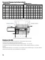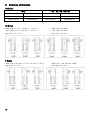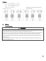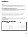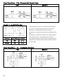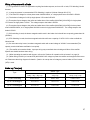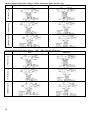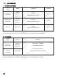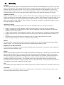
1
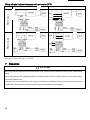
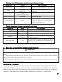
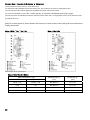
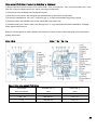
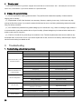
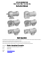
GTR MID GEARMOTORS
1/8 Hp ■ 1/4 Hp ■ 1/2Hp ■ 1 Hp ■ 2 Hp ■ 3 Hp
Instruction Manual
Safe Operation
●The Gearmotor should be operated by a skilled and qualified person. The contents of this Instruction Manual should be
carefully read and understood before operating this product.
●This Instruction Manual should be accessible to the person who operates this product.
●This Instruction Manual should be kept in a convenient place for the operator's easy reference.
Manufacturer
Brother International Corporation
Address
100 Somerset Corporate Blvd, Bridgewater, NJ 08807
TEL
866-523-6283
FAX
908-575-3743
E-MAIL
[email protected]
WEB
www.brother.com
Thank you for your purchasing this product.
Potential injuries and/or damage caused by mishandling equipment are classified into two categories, "Danger" and
"Caution". The definitions of the classifications are given below with the corresponding graphic symbols.
!
Mishandling the equipment may result in a dangerous situation and
!
Mishandling the equipment may result in a dangerous situation and
Danger
CAUTION
may lead to serious or fatal injury to personnel.
may lead to medium to light injury or damage to the equipment.
Please be aware that even items marked with "CAUTION" may cause fatal accidents. Therefore, be sure to follow the
instruction, for every item described is very important.
!
DANGER
●Use an explosion-proof motor when any explosive or flammable gases are present. Failure to observe this warning may cause
explosion, spark, fire, electric shock, physical injury, and/or damage to the equipment.
●People in charge of transportation, installation, wiring, operation, maintenance, and inspection of the equipment should have
sufficient knowledge and technical skill to install electrical and mechanical products. Failure to observe this warning may cause
explosion, spark, fire, electric shock, physical injury, and/or damage to the equipment.
●Do not repair or wire the equipment with the electric power on. Cut the power before working on this product. Failure to observe
this warning may cause electric shock.
●If the equipment incorporating this gearmotor is used in a system for human transport, furnish it
with sufficient protective devices for safety and follow any and all local or national codes. Failure to observe this warning may
cause physical injury, death and/or damage to the equipment.
●If the equipment is to be used to drive an elevator, be sure to furnish it with safety devices to prevent the elevator from
accidentally falling. Failure to observe this warning may cause physical injury and/or damage to the equipment.
●Be sure not to get water or oil/grease into the brake unit. Failure to observe this warning may cause brake failure by decreasing
brake holding torque.
! CAUTION
●Do not use this gearmotor under conditions other than specified on the nameplate or product specifications. Failure to observe
this warning may cause electric shock, physical injury and/or damage to the equipment.
●Do not insert your fingers or any other object into the terminal box, lead wire exit, fan cover, or any other aperture of the
gearmotor. Failure to observe this warning may result in electric shock, physical injury, fire and/or damage to the equipment.
●Do not use a damaged gearmotor. Failure to observe this warning may result in physical injury and/or fire.
●Do not remove the nameplate.
●The manufacturer will not warrant and will not be responsible for any product modified or repaired by the user.
2
Contents
1Check When Unpacking
P.3
7 Operation
P.20
2Transportation
P.3
8 Inspection and Adjustment
P.22
3Installation
P.4
9 Trouble Shooting
P.26
4Connecting with Other Equipment
P.5
10 Disposal
P.27
5Direction of Rotation
P.12
11 UL/CSA/CE
P.28
6Wiring
P.13
12 Warranty
P.29
1
Check When Unpacking
When unpacking the carton, please check the following items. If you have any problems or questions, please contact the
dealer from which the product was purchased or Brother International Corp sales office.
! CAUTION
Check whether the product is the product you ordered. Installing the wrong gearmotor on your equipment may cause
physical injury and/or damage to the equipment.
(1)The ordered product(s), the contents of the box or crate, and the rating indicated on the nameplate are correct.
(Type,Reduction Ratio, RPM, Horsepower or Watts, Voltage, Frequency, etc.)
(2)No accidental damage to the product during transportation has occurred.
(3)Screws or nuts are not loose.
(4)In case of a brake equipped gearmotor, be sure the rectifier is enclosed.
(5)In case of a 1/8 Hp single-phase motor be sure the capacitor is enclosed.
(6)In case of F or F3 series hollow bore/shaft mount type be sure the bore safety cap is enclosed.
2
Transportation
!
DANGER
When a product is lifted for transportation, be careful. If a product is dropped and lands on any part of your body it may cause serious
injury.
3
! CAUTION
●Avoid dropping products during transport. When an eyebolt or eyeplate is provided on a gearmotor or reducer, confirm it
is secure before using it. After installing the gearmotor or reducer in the equipment do not hoist the entire machine using
the eyebolt or eyeplate. Failure to observe this warning may cause physical injury and/or damage to the equipment.
●Before lifting the product confirm it's weight using the packing box, product catalog, or by weighing it. Use a lifting device
that has enough capacity to handle the weight of the gearmotor. Failure to observe this warning may cause physical injury
or damage the equipment.
●If the product is packed in a wooden crate, please do not use a forklift to lift it from the bottom. The crate is not designed
for use with a forklift in that manner. If using a forklift, please use a belt to lift the wooden box from the top.
3
Installation
Proper installation of a product will ensure reliable service and maximum life.
! CAUTION
●Do not place any flammable object near the gearmotor. Failure to observe this warning may cause fire.
●Do not allow interference with the ventilation of the gearmotor. Be sure to observe the spacing requirements for
adequate air flow around the gearmotor. In the case of a fan cooled model, do not block the vent holes on the fan cover.
Failure to observe this warning may result in abnormal overheating and/or injury or fire.
●Do not step on a gearmotor. Do not use a gearmotor as a grip to hoist yourself onto a machine. Failure to observe this
warning may cause physical injury.
●Do not touch the edge of the shaft of the gearmotor or the key groove of the bore with your bare hands. Failure to
observe this warning may cause physical injury.
● Food machine regulations may prohibit the possibility of oil or grease getting into the food area. If this is the case,
please use a drip pan to prevent lubrication from getting into the food area.
Alternatively, please request that appropriate
food grade lubricants are applied.
●Leaking oil may cause products to fail.
●Vibration resulting from improper installation of the gearmotor or from other sources should be under 0.5G.
(1)Proper location for installation
Ambient Temperature: 14 to 104F (-10℃ to 40℃)
Ambient Humidity: 85% max.
Altitude: Sea level to 3280 feet (1,000m max.)
Environment:
Standard Type: Well ventilated free from vapor and dust.
IP-65 Type: Well ventilated free from vapor
Note: In a hazardous environment where any explosive and flammable gases exist use an explosion-proof motor.
Installation Location: Indoors
(2)Direction of Installation
This product can be installed in any direction and any angle due to a grease lubrication system.
4
(3)Method for Installation
Tightening Torque for Torque Arm
a) Mounting a foot or flange type with a shaft.
Fixing Hole
Metric
Tightening
Fixing
Inch Bolt
Tightening
Size
Torque
●Secure the product with four bolts on a flat and
Metric
Bolt
Torque (N-
Hole
machined surface free from vibration.
(mm)
Size
m)
Inch (in)
●Roughness of the mounting surface should be less than
5.5
M5
2.9
0.20
3/16-18
25
0.3mm.
6.5
M6
4.9
0.25
¼-20
43
8.5
M8
13
0.33
5/16-18
115
such that it can handle the weight of the gearmotor or
11
M10
25
0.43
3/8-16
220
reducer.
13
M12
44
0.51
7/16-14
390
15
M14
69
0.59
7/16-14
390
18
M16
108
0.71
5/8-11
955
22
M20
294
0.75
5/8-11
2600
b) Mounting a hollow bore/shaft mount type.
●The driven shaft should be large enough and supported
●Forces other than the turning or reactive force should
not be imposed on the torque arm.
●For frequent start/stops or forward/reverse secure the
torque arm with bolts to keep it axially secure.
(4) Ventilation Around the Gearmotor
Minimum Dimension”A’ for Proper Ventilation
Standard Motor
IP-65 Motor
1 Phase, 3 Phase
3 Phase
Horsepower
Brake
Brake
Motor
Motor
Motor
Motor
1/8 Hp
64
64
64
64
¼ Hp
79
79
79
102
½ Hp
79
79
79
116
1 Hp*
79
79
79
137
2 Hp*
101
101
101
n/a
3Hp*
101
101
101
n/a
* The 1 Hp, 2Hp, and 3 Hp are not available in 1 Phase.
(in-lb)
Any Reducer Type Applies
G3, H2, F, or F3
Note: The dimension “A’ is the space required for ventilation and for easy removal of the fan or brake cover and
adjustment of the brake gap “g” for brake equipped gearmotors. Gearmotors should be mounted to allow ventilation and
free air flow around the entire motor diameter. Good ventilation prolongs product life.
4
Connecting With Other Equipment
! CAUTION
●When connecting the gearmotor to a load with a chain or belt, make sure of the shaft parallel alignment is precise. Make
sure the belt/chain tension is properly adjusted and pulleys or sprockets are parallel.
●When direct coupling, make sure the concentric alignment of shafts is precise.
●Before operation, make sure the set screws for the sprockets, pulleys or coupling are securely tightened. Failure to
observe this warning may cause serious injury and/or damage to the equipment.
●Safety guards should be furnished around rotating parts and securely in place before starting the equipment.
● Do not over tension chain or belts. Damage to the gearmotor may occur due to excessive overhung load.
● Avoid excessively rigid direct couplings as damage may occur to the bearings due to high overhung load.
5
1Direct Connection
Connect the reducer to the other equipment precisely, so that the center of the shaft of both machines will be fully aligned.
●The displacements δ and θ should be minimized as much as possible.
●The displacements δ and θ differ according to the type of coupling. They should be within the allowable value defined by the
respective manufacturer.
●Reference: In case of coupling via chain, δ should be within 2% of the roller chain pitch and δ should be within 1°.
2
Attaching Chains, V-Belts, Gears, etc.
(1)The center of the shaft of the reducer and that of the other equipment should be parallel.
(2)The tension of Chains of V-Belts must be perpendicular to the center of the shaft.
(3)Excessive tensioning of the chain or V-belt may result in damage to the bearings of the shaft.
(4)If the chain is too loose (or slack), shock loading will occur when the drive shaft starts rotation. This can result in
damage to the reducer and/or the equipment. Therefore, adjust the tension of the chain properly.
Proper Installation
● The tension of V-belt and chain are properly set.
● The pulley and sprocket are properly positioned on the gearmotor shaft. The chain/V-belt is as close to the gearmotor
output shaft bearing as possible. This minimizes overhung load and promotes longer bearing life.
Improper Installation
● The Chain is too loose.
● The sprocket is applied to the shaft improperly. The chain or V-belt is set too far from the gearmotor output shaft
bearing. This may lead to excessive overhung load (OHL) and shortens bearing life.
6
3 Attaching/Detaching a Driven Shaft to/from F or F3 Type Hollow Shaft
●Attaching a Driven Shaft to the Reducer Hollow Shaft
(1)Apply an extreme pressure agent such as molybdenum disulfide on the surface of driven shaft and the bore of the hollow shaft to
avoid seizing.
(2) If the load is uniform (low impact) a loose fit is recommended for the tolerance of driven shaft.
(3) If a shock load or heavy radial load will be applied to the shaft, the fit should be tighter.
(4) If the fit is tight tap on the end of the hollow drive shaft gently with a plastic or wooden hammer. Do not to hit the gear casing.
(5) If the fit is extremely tight, smooth insertion can be achieved if you prepare a jig shown in the figure below.
(6) The length of the driven shaft and the fixing key should be positioned within the space where the bore tolerance is tight
(The key should not be seated in the central relief area where the bore is larger).
(Spacer, nut, bolt, key and jig parts are not supplied by Brother)
●Connecting Reducer with Driven Shaft
(Spacer, nut, bolt, key and jig parts are not supplied by Brother)
(Note: Excessive tightening of the bolt may cause the deformation of the snap ring.)
7
(End plate and bolt parts are not supplied by Brother)
!
DANGER
A plastic bore cover is supplied with each FS, F2S, or F3S type unit to cover the exposed rotating bore. If you cannot
secure the safety cover supplied, please prepare a cover yourself. Failure to cover the exposed rotating bore may result
in damage to the equipment or injury.
(Spacer, positioning spacer, bolt and snap ring are not supplied by Brother)
Note) The positioning spacer should not have a tight fit. It should have a loose fit and be concentric such that it does not
interfere with the I.D. of the bore as it rotates. Excessive tightness or inaccuracy of the spacer's diameter may be a cause
of rubbing interference with the bore. The positioning spacer is usefull when the resulting position of the driven shaft is not
known. In case the length of the driven shaft is precisely known, the positioning spacer is not necessary. A properly
applied positioning spacer does promotes easier removal of the shaft from the bore.
8
●Recommended Size for Securing Parts
Inch Dimension Bore
Metric Dimension Bore
Bolt
Bore
Spacer
O.D.
I.D.
T
(in)
(in)
(in)
1/4-20x1.25
0.73
0.28
1/4-20X0.75
1/4-20x1.25
0.98
1.2500
5/16-18X0.75
5/16-18x1.5
1.4375
3/8-16X1.25
1.6875
Bolt
Bore
Spacer
O.D.
I.D.
T
(mm)
(mm)
(mm)
M6X30
19.5
7
3
M6X16
M6X30
24.5
7
4
30
M8X20
M8X40
29.5
9
5
0.188
35
M10X25
M10X40
34.5
11
5
0.43
0.250
45
M10X25
M10X50
44.5
11
5
1.92
0.51
0.250
50
M12X30
M12X60
49.5
13
6
1.98
0.51
0.250
55
M12X30
M12X60
54.5
13
6
(mm)
Internal
External
0.125
20
M6X16
0.28
0.125
25
1.23
0.35
0.188
3/8-16X1.75
1.42
0.43
3/8-16X1.25
3/8-16X2
1.67
1.9375
7/16-14X1.25
7/16-14X2.5
2.0000
7/16-14X1.25
7/16-14X2.5
(mm)
Internal
External
0.7500
1/4-20X0.75
1.0000
Figure- 5 Recommended Size of Securing Parts
9
Recommended Dimensions of the Shaft from the Shoulder
Inch Dimension Bore
Bore
Metric Dimension Bore
Shaft (Inch Dimension)
Diameter
Bore
O.D.
L1
L2
L3
L4
Key
Tap
(in)
(in)
(in)
(in)
(in)
(in)
T
0.7500
0.7500 in
+0.0/-0.0008
0.945
3.125
1.500
0.1875
0.1875
1.0000
1.0000 in
+0.0/-0.0008
1.063
3.938
2.000
0.2500
0.2500
1.2500
1.2500 in
+0.0/-0.0008
1.299
4.000
3.375
1.4375
1.4375 in
+0.0/-0.0010
1.496
4.500
1.6875
1.6875 in
+0.0/-0.0010
1.969
1.9375
1.9375 in
+0.0/-0.0010
2.0000
2.0000 in
+0.0/-0.0012
(Inch)
Diameter
Shaft (Metric Dimension)
(Metric)
O.D.
L1
L2
L3
L4
Key
Tap
(mm)
(mm)
(mm)
(mm)
(mm)
(mm)
T
1/4-20X0.50
20
20 h7
24
80
30
6
6
M6X12
1/4-20X0.50
25
25 h7
27
100
37.5
8
8
M6X12
0.2500
0.2500 5/16-18X0.63
30
30 h7
33
102
45
8
8
M8X16
2.938
0.3750
0.3750
3/8-16X0.75
35
35 h7
38
117
52.5
10
10
M10X20
5.375
3.375
0.3750
0.3750
3/8-16X0.75
45
45 h7
50
137
67.5
14
14
M10X20
2.165
5.375
3.938
0.5000
0.5000
7/16-14X1.0
50
50 h7
55
138
75
14
14
M12X24
2.402
7.125
4.000
0.5000
0.5000
7/16-14X1.0
55
55 h7
61
182
82.5
16
16
M12X24
Note: Refer to the product catalog for Dimensions L and P.
T
Shoulder
L4
L3
L2
Figure-6 Recommended Dimensions of the Driven Shaft
Designing your Own Shaft
The usable key length “L3” should be greater than 1.5X the diameter of the driven shaft.
The Key should be engaged with at least half of the length L1.
The minimum length of shaft engaged inside the bore is approximately (L - L1) + ((L1-P)/2).
For dimensions L and P refer to the product catalog, the www or request a drawing from Brother or your Brother
distributor.
The recommended dimension L2 is not essential. If your application requires a different length or if you prefer a different
method of securing the shaft, it may be acceptable for your application.
10
Removing the Shaft from the Hollow Bore.
Avoid applying excessive force to the casing and/or the hollow shaft. Smooth detachment can be obtained by using a jig as shown in
the figure below.
Figure-7 Jig for Removing the Shaft
(Spacer w/ tap, disk, bolt and snap ring are not supplied by Brother)
Attaching a Motor to a NEMA 56C Reducer
●Attaching Procedure
(1)Confirm the key is securely inserted in the key slot of the motor input shaft
(2)Align the keyway of the motor with the keyway of the reducer input bore.
Gently insert the shaft into the reducer bore.
(3)Confirm the motor shaft is securely inserted with the key fully engaged.
(4) Secure the motor to the reducer using 4 flange bolts.
(bolts not provided by Brother)
●Cautions when Attaching the Motor
(1)Wipe off any rust and dust and apply and anti-seizing agent to the motor shaft.
(2)When inserting the motor shaft, do not hit the motor or reducer with a hammer, nor forcibly insert the motor shaft.
(3) Take advantage of the tightening force of the bolts to fully insert the shaft if required. Failure to observe this warning may cause
damage to the bearing and/or abnormal noise
(4) Observe the motor weight limit guidelines shown in the Table.
●Motor Mass Limit Guideline
ℓ (in) : Length from reducer flange to center of motor
W (lb): Weight of the motor in lbs.
Horsepower (4 Pole,
Induction motor)
1/8 Hp, ¼ Hp
½ Hp
1 Hp
2 Hp
3 Hp
ℓ x W =M
M < 240 in-lb
M< 275 in-lb
M< 300 in-lb
M< 735 in-lb
M< 825 in-lb
(1)The limit of vibration that a gear reducer can withstand is 0.5G. If the vibration is greater than 0.5G, or if the motor mass limit is
above the “M” limitation, the casing of the reducer and/or the reducer flange may be damaged. The motor may fall off the reducer and
cause injury of damage the equipment. The motor should be supported by a separate device supplied by the user for safety.
(2)Before using other manufacturer’s motors with our reducer, you should carefully read this Instruction Manual and understand the
contents. The failures of a reducer caused by poor installation will not be warranted.
11
5 Direction of Rotation
G3 Series
1/8 Hp
¼ Hp, ½ Hp, 1 Hp, 2 Hp, 3 Hp
5:1 to 50:1
Same Direction
5:1 to 30:1
Same Direction
60:1 to 200:1
Counter Direction
40:1 to 200:1
Counter Direction
300:1 to 1200:1
Same Direction
300:1 to 1200:1
Same Direction
H2 Series
1/8Hp, 1/Hp: 5:1~60:1 & 600:1~1500:1
1/8Hp, 1/Hp: 80:1~450:1
½ Hp, 1 HP:5:1~60:1 & 300:1~1500:1
½ Hp, 1 Hp: 80:1~240:1
2 Hp, 3 Hp: 5:1~30:1
2 Hp, 3 Hp: 40:1~240:1
F Series
1/8Hp, ¼ Hp, ½ Hp, 1/Hp: 5:1~60:1 & 300:1~450:1
1/8Hp, ¼ Hp, ½ Hp, 1/Hp: 80:1~240:1
2 Hp, 3 Hp: 5:1~30:1
2 Hp, 3Hp: 40:1~240:1
12
F3 Series
1/8 Hp:
5:1~60:1 and 300:1~1500:1
¼ Hp:
5:1~60:1 and 300:1~1200:1
½ Hp:
5:1~60:1 and 300~600:1
1/8 Hp, ¼ Hp, ½ Hp, 1 Hp, 2 Hp: 80:1~240:1
1 Hp: 5:1~60 and 300:1
3 Hp: 80:1~120:1
2 Hp, 3 Hp: 5:1~60:1
6
1
Wiring
Direct Connection
!
DANGER
●When connecting power to the machine, follow the instructions shown on the connection diagram in the terminal box or
in this Instruction Manual. Failure to observe this warning may cause electric shock or fire.
●Do not bend, pull, or tuck motor cables or lead wires forcibly. Failure to observe this warning may cause electric shock.
●Be sure to ground the earth terminal, lead wire, or lug. Failure to observe this warning may cause electric shock.
●Be sure to use the power source specified on the name plate. Failure to observe this warning may cause the motor to
burnout and/or fire.
●Avoid exposing the power rectifier or capacitor to water. Failure to observe this warning may cause electric shock,
damage to the equipment, or fire.
13
! CAUTION
●1/8 Hp single-phase motors have a thermal protector is built in. If you suspect the thermal protector has tripped, switch off the
power to the gearmotor and/or the machine before attempting any inspection.
● 1/8 Hp single phase motors trip temperature is 120℃±5℃, Reset temperature: under 105℃. The gearmotor will be hot if the
thermal has tripped. Do not touch it with your bare hand as this will cause a burn injury.
●Do not touch the terminals or un-insulated wire connections when inspecting the insulation resistance. Failure to observe this
warning may cause electric shock.
●Wires should be connected properly using the specified electrical standard or safety code. Failure to observe this warning may
cause electric shock, fire or physical injury.
●Three phase motors are not equipped with thermal protective devices. Other protective devices such as a circuit breaker, fuse,
or thermal relay are recommended. If “CE’ is required, a thermal relay certified for use in Europe should be used. The thermal
set value should be the same as the current value specified in the name plate. Failure to observe this warning may cause
damage to the equipment, electric shock, fire or physical injury.
●When operating a gearmotor not connected to a load, remove the key from the output shaft. Failure to observe this warning
may cause physical injury.
●Check the direction of rotation before connecting the gearmotor to the machine's load. Rotation in the wrong direction may
cause physical injury and/or damage to the equipment.
●If a 460V class inverter is used to drive the motor, use a control filter or a reactor with the inverter. Breakdown of motor
insulation due to repetitive and/or extreme voltage spikes caused by normal operation of the inverter may cause damage to the
equipment or fire.
●1/8 Hp single phase motors use a continuous running type capacitor. Do not substitute a starting capacitor intended for
intermittent duty use. A starting type capacitor will fail when used with a permanent split capacitor motor. Use of a starting
capacitor may cause damage to the equipment or failure of the capacitor. For replacement capacitors, please consult Brother or
your Brother Distributor.
●Do not damage the vinyl coating of the capacitor. Damage may cause electric shock.
●Voltage drop in the wiring should be kept above 2%. Excessive length of wiring may cause a severe voltage drop. Voltage
drop reduces starting capacity and may result in the load not starting.
●When reversing either a three phase or a single phase gearmotor be sure to fully stop rotation before starting in the reverse
direction. Failure to completely stop before reversing may cause physical injury and/or damage to the equipment.
● Reversing a 1/8 Hp single phase PSC motor without completely stopping first may result in the motor not reversing and
running in the same direction. This may cause physical injury and/or damage to the equipment.
●When using a gearmotor with a brake do not energize the brake coil continuously while the motor is not running. The brake
coil of totally enclosed, fan cooled motors may rely on the motor fan for cooling. Continuous operation without the effect of the
fan may cause the brake coil to burn out and/or fire.
●Totally enclosed, non-ventilated, brake-equipped motors do not rely on the fan for cooling. However, continuously energizing
the coil without motor operation may still cause damage.
●If a gearmotor with a brake is used as a lift or hoist; DC Switching wiring should be used. Failure to use DC Switching may
result in the lift or hoist falling and causing damage to the equipment or physical injury.
14
Special Notes About Wiring
(1)The brake rectifier (A100-D90 or A200-D90) contains diodes. Improper wiring may cause a fatal short-circuit and
damage or destroy the rectifier. Special care should be used when wiring.
(2)The brake circuit relay for AC Switching should be an electro-magnetic switch with the capacity greater than 6A
(AC200V).
(3) The brake circuit relay for DC Switching should be an electro-magnetic switch with a capacity of (1A) DC110V.
(4) If a noncontact relay is used an electromagnetic switch with a rated voltage of AC240V is recommended. (The
capacity to switch half-wave rectification is required)
(5)The direction of rotation of the output shaft varies according to the reduction ratio of the gear head. Be sure to
confirm the gear ratio and the direction of rotation before wiring and starting.
(6)The voltage between the capacitor terminals of a single-phase motor will become nearly twice that of the power
source of the motor. Therefore be sure to insulate wires at the terminals for safety.
Special Notes About Grounding
①Ground should be connected to the provided ground terminal, lead wire, or lug.
②The cross-section of the earth wire should be AWG18 (0.87mm2) minimum for 1/8 Hp, ¼ Hp, or ½ Hp motors.
③The cross-section of the earth wire should be AWG16 (1.25mm2) minimum for 1 Hp, 2 Hp, or 3 Hp motors.
④ The earth wire should be longer than the lead wire of the power source of the motor.
Wiring a Gearmotor
For standard gearmotors, the wiring described below is recommended. The direction of rotation referenced is as viewed
from the back of the motor. Counter clockwise is the forward direction for 3-phase motors. Clockwise is the forward
direction for single-phase motors.
Three Phase Motors 1/8 Hp, ¼ Hp, 1/2Hp, 1 Hp, 2 Hp, 3 Hp
208/230V
460V
15
Single Phase Motors: 1/8 Hp (Permanent Split Capacitor Type)
115V
220/230V
Capacitor “C” used with PSC Type Motor
●1/8 Hp single phase motors are permanent split capacitor (PSC)
type motors. The starting torque of a PSC motor is 80%~85%
●PSC motors use a capacitor that remains in the circuit
permanently. The capacitor needs to be mounted separately by the
User.
●Be careful not to substitute an intermittent duty “starting capacitor”
[mm]
for use with a PSC motor. Consult brother if you are unsure.
Motor Voltage
Capacitor Voltage
Capacitance
115V
220V
24 µFd
220/230V
440V
6 µFd
●The capacitor Voltage is 2X that of the Motor Voltage because the
voltage across the capacitor terminals will become nearly 2X that of
the input voltage.
Single Phase Motors: ¼ Hp, ½ Hp (Capacitor Start type)
115V
16
220/230V
Wiring a Gearmotor with a Brake
(1)If a gearmotor is used in an application requiring fast brake response, such as a lift or hoist, "DC Switching" should
be used.
(2)A surge suppressor is recommended if DC Switching is required. (Varistor Voltage 423~517V)
(3)The brake coil voltage for a three phase motor 208/230V/460V, or a single phase motor 220/230V is DC90V.
(4) The brake coil voltage of a 1/8 Hp single phase 115V model is DC45V.
(5)The required input voltage to the yellow and white wires of the rectifier (A200-D90 [A100-D45]) for single phase
115V motors is single phase 115VAC. The voltage output to the brake is DC45V.
(6)The required input voltage to the yellow and white wires of the rectifier (A200-D90 [A100-D45]) for three phase
motors 208/230V/460V, or for single phase 220/230V motors is single phase 220/230VAC. The voltage output to the
brake is DC90V.
(7)If AC switching is used, the electro-magnetic switch used in the brake circuit should have a capacity greater than 6A
(AC200V).
(8)If DC Switching is used, the electro-magnetic switch should have a capacity of 1A DC110V in order to shield the
inductive load.
(9)If a noncontact relay is used, an electro-magnetic switch with a rated voltage of AC240V is recommended (The
capacity to switch half-wave rectification is required).
(10)The rectifier unit contains diodes. Improper wiring may cause fatal short-circuiting and failure of the rectifier.
Special care should be taken when wiring.
(11)When operating the machine with inverter, refer to the "Cautions for operation with an inverter" on page 19.
(12)When wiring for 460V (no inverter/VFD) the 220/230V AC voltage to power the rectifier can be tapped off the motor
coil. Please see the wiring diagrams for details. (Caution: do not tap the coil voltage to power a brake coil if an inverter
(VFD) is used.
Brake Lag Time [sec]
Type
Motor Type
Three Phase: 208/230/460V
1/8Hp, ¼ Hp, ½ Hp, 1 Hp
Three Phase 208/230/460V
2 Hp, 3 Hp
Single Phase 115V, 220/230V
1/8 Hp, ¼ Hp, ½ Hp
(1) DC Switching
0.005~0.015
0.005~0.02
0.005~0.015
(2) AC Switching(A)
0.03~0.10
0.05~0.15
0.03~0.10
(3) AC Switching(B)
0.10~0.20
0.20~0.40
0.10~0.20
17
Brake Equipped Single Phase Motor: 1/8 Hp, Permanent Split Capacitor Type
115V
220/230V
DC Switching
AC Switching(A)
AC Switching(B)
Brake Equipped Single Phase Motor: ¼ Hp, ½ Hp, Capacitor Start type
115V
DC Switching
AC Switching (A)
AC Switching(B)
18
220/230V
Brake Equipped Three Phase: 1/8 Hp, ¼ Hp, ½ Hp, 1 Hp, 2 Hp, 3 Hp
208/230V
460V
DC Switching
AC Switching (A)
AC Switching(B)
Note: If an inverter (VFD) is used, the brake rectifier cannot be powered using the output side of the inverter. Please see the special
inverter (VFD) wiring diagrams. The above diagrams are not suitable.
5 Cautions for Operation with an Inverter (VFD)
(1)Compared to operation using a general power source, higher temperature rise, noise and vibration may be
observed when using an inverter.
(2) Low speed (low frequency) operation naturally reduces the cooling effect of the fan. This may cause abnormal
temperature rise. Please use caution and check to if the surface temperature remains below allowable levels (176F, 80C)
(3)When driving a gearmotor equipped with a brake, the brake may malfunction due to voltage drop caused by normal
operation of the inverter (VFD) if the rectifier is powered by the output side of the inverter(VFD). To avoid this, it is
imperative to bypass the inverter when wiring the brake. See the special wiring diagrams for use with inverters (VFd) in
this manual.
(4) When using a 460V inverter (VFD), it is recommended that a suitable filter or reactor be used to suppress excessive
repetitive voltage spikes caused by the normal operation of a 460V inverter (VFD). Failure to take this precaution may
result in premature burn-out of the motor and breakdown of the motor insulation. Please consult the inverter manufacturer
for the proper size of the filter or reactor as it depends on the inverter parameter settings, length of wire, etc.
(5)When using a 460V inverter with a brake, do not tap the motor windings to power the rectifier (T8-T5, T9-T6). Due
to voltage drop caused by normal operation of the inverter (VFD), power from tapping the coil wires is not reliable and will
result in brake failure. The rectifier (A200-D90) must be powered with a separate 200~230V 1 phase source.
Alternatively, if the input power source is 115V, please consult brother for the purchase of a rectifier that accepts 115VAC
and has an output of 90VDC (Ref P/N: A100-D90 rectifier). The A200-D90[A100-D45] rectifier is not suitable for 115V
power.
19
Wiring a Brake Equipped Gearmotor with an Inverter (VFD)
208/230V
460V
AC Switching
460
220/230V
Note
*
460V
DC Switching
Yellow
220/230V
Note
*
White
Note *: If the Alternate input power is 115V, please purchase an A100-D90 rectifier and substitute it for the A200-D90.
The required voltage to the brake coil is 90VDC.
7
Operation
! DANGER
●Do not operate the gearmotor with the terminal box cover opened. Failure to observe this warning may cause electric
shock.
●Do not approach or touch rotating parts such as a shaft while the machine is running. Failure to observe this warning
may cause physical injury.
●If power loss occurs; switch off the power supply to the machine. Unexpected recovery of electric service may cause a
sudden start of the gearmotor and cause physical injury and/or damage to the equipment.
20
! CAUTION
●The gearmotor may become hot during operation. Do not touch it with your bare hands. Failure to observe this warning
may cause burn injury.
●When a gearmotor is running abnormal, stop it immediately. Failure to observe this warning may cause electric shock,
physical injury or fire.
●Do not overload a gearmotor. Failure to observe this warning may cause physical injury and/or damage to the
equipment.
●Do not touch any current-carrying part of the capacitor used for a single-phase motor until it has been discharged
completely. Failure to observe this warning may cause electric shock.
●When reversing the direction of a single-phase motor, it must come to a complete rest before starting rotation in the
opposite direction. If a single phase motor does not come to a complete stop before reversing, the direction of rotation
may not change. Failure to stop the motor completely before reversing may cause physical injury or damage to the
machine.
●Do not stop or stall a motor forcibly. It may cause damage to the machine.
●If a 1/8 Hp single phase, permanent split capacitor (PSC) motor is stalled forcibly, the motor may spontaneously rotate in
the opposite direction. This may cause damage to the equipment or physical injury.
1 Check these issues before turning the power switch on:
(1)Wiring and connections are done properly to required codes.
(2)Fuses and thermal relays of proper capacity are used.
(3)Installation and the connection with the machine is properly done.
(4)The earth terminal, lead wire, or lug is properly grounded.
[Note] When using a water-resistant IP-65 motor in the circumstance where water may be persistently present during
operation, it is recommended to use ground fault circuit interrupter for safety.
2 Check these issues during the initial test run:
(1)Confirm the direction of rotation for 1~2 seconds by starting the motor in the unloaded condition. If you find
improper rotational direction, change the wiring.
(2)Test run the gearmotor with the machine in an unloaded condition. When no defect is observed, add load gradually
and eventually start operation under the full load.
3 Check these issues during operation:
(1)Confirm there is no abnormal noise and/or vibration. Stop operation of the gearmotor immediately if abnormal
noise or vibration occurs. Failure to observe this warning may cause physical injury and/or damage to the equipment.
(2)Confirm if the surface temperature of the gear case and motor frame does not exceed 176F (80℃). Do not touch
the surface of the gearmotor with your bare hands. Failure to observe this warning may cause a burn injury.
21
8
Inspection and Adjustment
! DANGER
●When inspecting and/or adjusting the machine while it is in operation, do not touch rotating parts such as a shaft. Failure
to observe this warning may cause physical injury.
●Do not attempt to disassemble the gearmotor while it is in operation. Lubricant may blow-out and cause a burn injury.
Opening the motor may cause electric shock.
●If the gearmotor is enclosed inside the equipment and you need to inspect it, be sure to immobilize the gearmotor drive
shaft and the machine drive shaft prior to inspection. Also, confirm the equipment is sufficiently cooled down before
attempting any inspection.
●During any inspection, please have support personnel outside the machine to watch safety conditions. If lubricant has
spilled it can be very slippery, please use caution. Failure to observe this warning may cause physical injury.
●Do not operate the equipment with safety guards off. Failure to observe this warning may cause physical injury.
[Inspection and Maintenance of Brake Parts]
●Do not operate the equipment with the manual release lever of a brake disengaged. Failure to observe this warning may
cause damage to the equipment, physical injury, or death.
●Before starting the equipment, make sure the brake is functioning properly. Turn the switch on and off and listen for the
“click” of the brake. Failure to observe this warning may cause malfunction of the machine, loss of brake function
resulting in damage to the equipment, physical injury, or death.
●Do not operate the equipment without the fan cover ( or brake cover ) installed after inspection and adjustment of brake
gap. Failure to observe this warning may cause wind-in and physical injury.
●Do not release the brake while the equipment is operating. Failure to observe this warning may cause the machine to
run out of control, damage the equipment and result in physical injury or death.
! CAUTION
●When measuring the insulation resistance do not touch the terminals. Failure to observe this warning may cause electric
shock.
●The surface of a gearmotor may be very hot. Do not touch it with your bare hands. Failure to observe this warning may
cause burn injury.
●When abnormal operation is observed; diagnose the fault according to the instruction manual. Do not operate the
machine until the cause of the fault is found and proper measures are taken to correct the matter.
●When measuring the insulation resistance of an explosion-proof type motor, confirm that there is no gas, vapor, or other
explosive substance around the unit. Failure to observe this warning may cause an explosion or ignition.
●Repairing, disassembling and reassembling of the equipment should be done only by an experienced technician. Failure
to observe this warning may cause electric shock, physical injury or fire.
●Improper disassembly of the gearmotor voids the warranty.
22
1
Daily Inspection: Following items should be inspected every few days.
Inspection Item
Method
Load Current
Ammeter
Compare it to the full load current on nameplate.
Human Ear
Noise
Vibration
Details of inspection
No abnormal rumbling, grinding, clicking, or
Detection Rod
ticking sound
Touch
(please wear a protective gloves)
Surface Temperature
Thermometer
No abnormal vibration on gear case or motor.
Less then 176F (80C)
No lubricant leaking from the casing joints, rotor
Grease Leakage
Visual
fan extension, terminal box, lead wire grommet,
cord exit, or output shaft seal.
2
Periodic Inspections: (In case of operating 8 hours a day)
Inspection item
Interval
Fixing Bolt
6 months
Check to see if the bolt is loose. Retighten if required.
Chain or V-belt
6 months
Check tension (loose or tight) and adjust to proper tension.
Insulation Resistance of Motor
6 months
More than 1MOhm when insulation resistors is 500V.
1 Year or
Check if the gap is within the allowable limit. Refer to Page
Brake Gap
Details of Inspection
1~1.5 Million Cycles
21. Adjust as instructed.
Check the thickness of the friction disk. Replace if the disk is
Brake Friction Disk
1 Year
less than 1.5 mm. Consult Brother or your brother dealer for a
replacement friction disk.
When any abnormality is found during the daily inspection, take proper measures to correct the situation.
3
Brake Gap “g” Adjustment for a Brake Equipped Gearmotor
! DANGER
1 When adjusting the gap disconnect the motor from the power source. Failure to observe this warning may cause physical
injury.
2
After inspection and adjustment of the gap, be sure to confirm the brake functions properly. Failure to observe this warning
may cause an accident or allow the machine to run out of control.
3
After inspection and adjustment of the gap, do not operate the motor with the fan cover (or brake cover) open. Failure to
observe this warning may cause physical injury.
Note: Brake Gap “g” Adjustment
After operation for an extended period of time, the friction disk of the brake wears and the gap (g) increases. When the
gap clearance becomes too large the armature cannot function and the brake will become ineffective or fail. Continuous
usage of a brake when the gap is out of specification causes excessive temperature rise in the brake coil and will lead to
coil failure. For safe operation, the brake gap should be inspected every 12 months or 1~1.5 Million cycles.
23
Standard Motor: Procedure for Brake Gap “g” Adjustment
① Remove fan cover in the case of a or the brake cover).
② Lift the tooth of the castellated nut from the securing slot. Also, loosen the set screw for single phase motors.
③ Press down the friction disk and tighten the castellated nut by hand until it is firmly locked.
④ Loosen the castellated nut 1000~1800. Confirm the gap “g” is within the acceptable range using a gauge.
⑤ Press the tooth of the castellated nut into the nearest slot on the friction disk. For single phase motors, secure setscrew as well.
⑥ Install the fan cover.
[Note] Do not allow grease or dust to adhere to the friction disc. Failure to observe this warning will cause a decrease in
braking performance.
Motor: 1/8 Hp, ¼ Hp, ½ Hp, 1 Hp
Motor: 2 Hp, 3 Hp
Set Screw ⑫ is only for 1 phase motors
Gap ‘g” Data: Standard Motors
Motor Horsepower / Type
24
Allowable Gap “g”
Proper Gap “g”
Three Phase
Single Phase
(mm)
(mm)
1/8 Hp, ¼ Hp
1/18 Hp, ¼ Hp
less than 2.3
1.9 +/- 0.1
½ Hp
n/a
less than 1.8
1.4 +/- 0.1
1 Hp
½ hp
less than 2.4
2.0 +/- 0.1
2 Hp, 3 Hp
n/a
less than 1.0
0.4 +/- 0.1
Water resistant IP-65 Motor: Procedure for Brake Gap “g” Adjustment
① Remove the fan cover in the case of a fan cooled model. Then, remove the fan. Then, remove the brake cover. In the
case of a 1/8 Hp non-vented unit (no fan), start by removing the brake cover.
② Lift the tooth of the castellated nut from the securing slot.
③ Press down on the friction disk and tighten the castellated nut by hand until it is firmly locked.
④ Loosen the castellated nut 1000~1800. Confirm the gap “g” is within the acceptable range using a gauge.
⑤ Press the tooth of the castellated nut into the nearest slot on the friction disk.
⑥ Install the brake cover. Check if there is any damage in the “o” ring of the brake cover before installation. If damage
exists, replace it with new one.
[Note] Do not allow grease or dust to adhere to the friction disc. Failure to observe this warning will cause a decrease in
braking performance.
Motor: 1/8 Hp
Motor: ¼ Hp, ½ Hp, 1 Hp
Gap ‘g” Data: water resistant IP-65 Motors
Three Phase
Allowable Gap “g”
Proper Gap “g”
Motor Horsepower
(mm)
(mm)
1/8 Hp
less than 0.8
0.30 +/- 0.1
¼ Hp, ½ Hp
less than 0.7
0.30 +/- 0.1
1 Hp
less than 0.9
0.30 +/- 0.1
25
4
Warning Label
A warning label is attached to a gearmotor equipped with a brake that has a manual release lever. If the label peels off or becames
hard to read, contact Brother or your brother distributor for a replacement label.
5
Grease, Oil seal and O-Ring
(1)All of our gearmotors employ grease lubrication. They are filled with a determined quantity of lubricant before
shipping from our factory.
(2)Replacement or refill of the lubricant is not necessary. However, replacing it once every 10,000 hours may help
prolong the life of the reducer. If you need to replace the lubricant, be sure to use factory authorized grease and consider
using our facility in the USA.
(3)Our machines are protected from grease leakage by an oil seal and/or o-ring. While our sealing is highly reliable, it
is recommended to protect the machine with an oil pan for safety. (Grease leakage may be observed when machine is in
trouble or at the end of a long life.)
(4)The life of oil seal will vary according to the condition of use. Therefore replacement under severe conditions may
be needed within 10,000 hours of use. If you need to replace the oil seal, be sure to use a factory authorized part. Repair
service from the factory is available as well.
9 Troubleshooting
1. Trouble Shoting a Gearmotor (no brake)
Trouble
Cause
Failure of Power Supply
Check the Power Source
Bad Wire Connections
Check the Electric Circuit
Failed Contact Switch
Repair / Replace the Relay
Motor Does Not Run, in the
Disconnected Stator Coil
Repair at Auth Facility
Unloaded Condition
3-phase Motor Running 1-phase
Check the Terminal Voltage
Capacitor Not Connected (1/8 Hp 1 Phase)
Connect the Capacitor
Governor Switch Malfunction
Repair at Auth Facility
Broken Gear, Shaft, Bearing
Repair at Auth Facility
Motor Does Not Run in the
Loaded Condition
Abnormal Temperature
Abnornal Noise
Voltage Drop
Check the Length of Wire
Worn Out Gear
Repair at Auth Facility
Overload Tripped
Reduce the Load
Overload Tripped
Reduce the Load
High Frequency of Starts/Stops
Reduce the Freq of Starts/Stops
Damage to Bearings
Repair at Auth Facility
Overvoltage or Undervoltage
Check the Voltage
Defective Bearing or Worn Out Gear
Repair at Auth Facility
Intermittent Noise-damaged Gear or Foreign
Substance in the Gearbox
Excessive Vibration
Grease Leakage
26
Trouble Shooting
Repair at Auth Facility
Worn Out Gear or Bearing
Repair at Auth Facility
Improper Installation or Loose Bolts
Tighten the Bolts
Loose Bolts, Nuts, or Screws
Tighten the Bolts, Nuts, or Screws
Damaged Oil seal
Repair at Auth Facility
2. Trouble Shooting a Gearmotor with a Brake
Trouble
Brake Does Not Work
Cause
Trouble Shooting
Incorrect Wiring
Check the Wiring
Damaged Switch or Rectifier
Replace/Repair
Foreign Substance or Oil on Friction Disk
Hold Torque Inadequate
Friction Disk Worn out
Brake Takes Too Long to Activate
(Thickness Less than 0.8 mm 1/32 in)
Motor Does Not Run
Motor
Overheats, Trips Thermal
Abnormal Brake Noise
Excessive Temperature
Remove Foreign Substance and/or Clean
off the Oil
Replace the Friction Disk
Excessive Load Inertia
Reduce the Load Inertia
AC Switching Used
Change to DC Switching
Wiring Incorrect
Correct the Wiring
Brake Gap “g” Too Large
Adjust the Brake Gap or Replace Friction
Disk.
Rectifier Failed
Replace the Rectifier
Brake Coils Disconnected or Shorted
Replace the Coil
Damaged Contact Switch
Repair or Replace the Switch
High Frequency of Braking (Stops/Min)
Excessive Load or Load Inertia
Reduce the Brake Frequency
(Fewer Stops/Min)
Reduce the Load or Load Inertia
3. Parts for Replacement/Repair
Contact Brother or your Brother distributor for the replacement brake parts. Please note that we will not warrant any defect
caused by improper replacement or repair completed by the user.
10 Disposal
! CAUTION
Gearmotors and lubricant should be disposed as general industrial waste.
27
11
UL/CSA/CE
1 UL/CSA Information
Hp Range
Phase
1/8 Hp
Single Phase
1/4Hp, ½ Hp
Single Phase
1/4Hp~3 Hp
Voltage
UL Standard
UL File No.
115 60 Hz,
UL2111
220V 60 Hz
Overheating Protection for Motors
230V 60 Hz
(Includes standards for UL1004)
115 60 Hz,
220V 60 Hz
230V 60 Hz
208/230/460V
UL1004
Standard for Safety, Electric Motors
UL1004
Standard for Safety, Electric Motors
Brother Gearmotors have the UL Component Recognition mark on the nameplate.
Brother gearmotors have the cUL Component Recognition for Canada mark on the nameplate.
2 C E Information
Hp Range
Phase
1/8Hp~1/2 Hp
Single Phase
Voltage
Standards
115 60 Hz,
EC Directive: 73/23/EEC
220V 60 Hz
230V 60 Hz
(Low Voltage Directive)
EN Standard: EN60034-1
1/8~3 Hp
Three Phase
208/230V/460V
(Regulations on Motors in General)
Brother Gearmotors have the “CE” mark on the nameplate.
Please consult Brother for Technical File Information or a Formal Declaration of Conformity.
28
E153713
E172017
E172017
12 Warranty
Warranty
All Brother gearmotor products are warranted against defects in materials and workmanship for a period of 2 years from
the date of our shipment. This constitutes Brother’s only warranty in connection with this sale, and is in lieu of all other
warranties expressed or implied, written or oral. There are no implied warranties of merchantability or fitness for a
particular purpose that apply to this sale. If performance guarantees are requested, they should be requested in writing.
Full consideration will be given to such requests when complete details of the proposed application are included.
Limitation of Remedy
Brother will repair or replace, at brother’s option, F.O.B. Brother’s factory, freight prepaid, any brother gearmotor proved
defective in materials or workmanship if immediate written notice of claim is made to Brother by Purchaser within 2 years
from the date of shipment. It is agreed that such repair or replacement is the exclusive remedy available from Brother.
Under no circumstances shall Brother be liable to anyone for any special, incidental or consequential damages, whether
the result of negligence or otherwise.
Warranty Exclusions
The Warranty of Brother gearmotor products does not cover and Brother makes no warranty with respect to:
1. Failures not reported in writing to Brother within the warranty period of 2 years after the date of shipment.
2. Failures or damages due to miss-application, abuse, improper installation or abnormal conditions of temperature,
humidity, dirt or corrosive matter.
3. Failures due to operation, either intentional or otherwise, above rated capacities or in an otherwise improper manner.
4. Product which has in any way been tampered with or altered by anyone other than an authorized representative of
Brother.
5. Expenses incurred by the Purchaser in an attempt to repair or rework an allegedly defective product.
6. Product damaged in shipment or otherwise without the fault of Brother.
Returns
No product will be accepted for return unless authorized in writing with a returned merchandise authorization (RMA)
number assigned. Any returned goods must be returned with transportation charges prepaid.
Regulatory Laws and/or Standards
It is the Purchaser’s obligation to install and operate all Brother gearmotor products in conformance with all applicable
national or local laws and safety codes.
Patents
Brother represents that its gearmotors are designed and manufactured such that they do not infringe on any United States
Patent(s), and that Brother will, at its expense, defend any claim charging such infringement and will save Purchaser
harmless from any adverse judgments resulting there from. Purchaser agrees to give Brother, prompt written notice of
any claim of infringement and to turn over to Brother the complete control of any litigation involving such claims
including the right to settle such claims. This indemnity does not apply to Products which are incorporated by the
Purchaser into Products which are changed to infringe a Patent or to Product which is used by Purchaser in performance
of a method or process which is charged to infringe a Patent.
Law
These Standard terms and Conditions of Sale shall be interpreted in accordance with the Laws of the State of New Jersey.
Severability
If any of the terms and Conditions shown here are determined to be invalid, illegal, or unenforceable the remainder of these
Terms and Conditions shall remain in full force and effect.
29
If you have any questions or concerns about our product, please contact the dealer or distributor from who purchased, or
contact the sales office of Brother International Corporation.
BROTHER INTERNATIONAL CORPORATION
100 Somerset Corporate Boulevard, Bridgewater, NJ 08808
Phone: 866-523-6283 Fax: 908-575-3743 E-mail: [email protected] , www.brother.com
2009Mid Ver.1