1
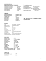
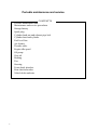
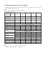
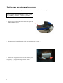
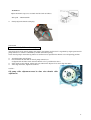
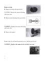
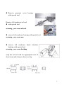
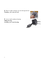
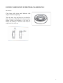
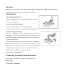
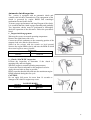
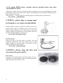
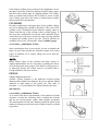
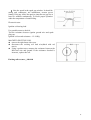
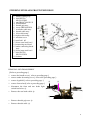
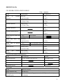
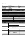
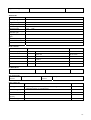
Service and Maintenance Manual (50ccm) 1 PREFACE The service manual has been specially prepared to provide all the necessary information for the proper maintenance and servicing. You have now a new type of scooter that has many techinal features such as: V-belt drive automatic transmission Forced air-cooling system CDI ignition system Electric starter system Those who will be servicing the scooter should carefully review the manual before performing any repair or services. Major modifications and changes incorporated later will be advised to GENERIC product distributor in each market. Therefore, if newest information is requested in the future, please contact the local GENERIC distributor. The scooters distributed in your country mignt differ in minor respects from the standard specification and, if they do, it is because some minor modifications had to be made to comply with the statutory requirements of your country. 2 3 GENERAL INFORMATION CONTENTS TYPE IDENTIFICATION FUEL AND ENGINE OIL BREAK-IN PROCEDURE PRECAUTIONS AND GENERAL INSTRUCTIONS SPECIFICATIONS 4 TYPE IDENTIFICATION ENGINE NUMBER ENGINE NUMBERLVFDUYHGRQUHDUFUDQNFDVHDV 6KRZQLQILJXUH Both FRAME NUBER AND ENGINE NUMBER are Designed specially for registering your scooter and ordering spare parts. FUEL AND ENGINE OIL Be sure to use specified fuel and engine oil. Some specifications are as follows: FUEL Unleaded, the minimum octane number is 95 or more. ENGINE OIL For GENERIC CCI SYSTEM, we recommend special engine oil, you can choose high quality two-stroke engine oil (without being diluted) if without special oil. GEAR OIL Use high quality, all-purpose SAE90 engine oil for scooter. BREAK-IN TIME General requirements are as follows᧶ Limit break-in speed᧶ At the first 1000KMS᧤600 miles᧥mileage᧨play throttle less than 4/5 throttle᧷ After mileage exceeds 1000KMS᧤600 miles᧥ ᧨play full throttle᧷ Don’t run engine too long during break-in time, and try to change throttle position. 5 PRECAUTIONS AND GENERAL INSTRUCTIONS Correctly abide by the following items when disassembling and assembling scooter: ႒ Don’t run engine indoors without ventilation; ႒ Be sure to replace new bushings, circlips, O-rings and cotter pins with new ones᧷ CAUTION It is forbidden to use the circlip removed from shaft, only use new one᧷ Be very carefull to install new circlip for fear that the end hatch of circlip exceeds required sliding surface for shaft᧷ After installing circlip, inspect whether it has been completely clipped into the groove. ႒ Fix bigger diameter bolt first when tightening cylinder head or cylinder, and tighten to specified torque gradually from inside to outside at diagonal order. ႒ Use special tools for some special requirements᧷ ႒ Use original components and recommended engine oil᧷ ႒ Keep each other’s safety when several persons do᧷ ႒ Inspect looseness and operating state of components after reassembling them.᧷ ႒ Take high care of gasoline, which is explosive, and never use gasoline as lotion. The words like warning, notice, note may turn out incessantly in the manual, which means: WARNING The personal safety of the rider may be involved. Disregarding the information could result in injury to the rider. CAUTION These instructions point out special service procedures or precautions that must be followed to avoid damaging the machine. NOTE it provides some special information, which keeps maintenance easier and important instructions clearer.. REPLACEMENT COMPONENTS Be sure to use genuine GENERIC components or their equivalent.. Genuine GENERIC components are high quality parts which are designed specially for GENERIC vehicle. CAUTION Damage to the scooter may result from use of replacement components which are not Equivalent in quality to genuine GENERIC parts, and it can lead to performance problems. 6 SPECIFICATIONS DIMENSION AND NET WEIGHT OVERALL LENGTH 1830 mm OVERALL LENGTH 695 mm OVERALL HEIGHT 1160 mm WHEELBASE 1295 mm NET WEIGHT 92 kg CHASSIS Front shock absorber Rear shock absorber Turning angle Front wheel Rear wheel Front brake Rear brake ENGINE Type Intake system Cylinder QTY. Bore Stroke Discharge Compression ratio Carburetor Air cleaner Starting system Lubricating system spring, no damp spring, oil damp 48º 120/70-12 130/70-12 Discij190 Drumij110 Transmission system Clutch system dry auto a centric Gearshift mechanism CVT stepless Operating mode of gears shift mechanism Automatic a centric Step less shift range 0.86~2.64 *the above data may be modified without any notification. two-stroke, air cooled piston-reed valve 1 40.0mm 39.6mm 49.8mL 6.9:1 flat inhale stopper style dry electric and kicking start pressure lubricating ELECTRIC Ignition mode CDI Ignition timing 150 at 1500RPM Spark plug BP8HS Storage battery YTX5L-BS Generator AC magneto Fuse 8A Headlight 12V—55W Turning light 12V/10W Taillight 12V—21/5W Meter light 12V/1.7W Oil level signal indicator light 12V/3W Turning signal indicator light 12V/3W CAPACITY FUEL TANK ENGINE OIL TANK GEAR OIL 5.2L 1L 0.1L 7 Periodic maintenance and service CONTENTTS Periodic maintenance and service schedule Maintenance and service procedures Storage battery Spark plug Cylinder head nut and exhaust pipe bolt Cylinder head and cylinder Fuel level line Air cleaner Throttle cable Engine idle speed Oil pump Gear oil Braking Tire Steering Front shock absorber Rear shock absorber Vehicle bolts and nuts 8 Periodic maintenance and service schedule The following table lists all required intervals for maintenance and service᧨following which, you are assured to have your scooter perform in the best way. Note Do more frequent maintenance when often riding on bad road Periodic maintenance table Interval (first 500 than Kilometer 500 3500 6500 9500 12500 I I I I I T T T T T ಧ C R C R ಧ R R R R Clean every 3000KM(2000 miles) I I I I all 3000km) Storage battery Cylinder head nut and exhaust pipe bolt Cylinder head and cylinder (change all 12000 km) Spark plug Air cleaner Idle speed rpm I Throttle cable play I I I I I Oil pump I I I I I Gear oil (75W90) R I ಧ I R I ಧ I R I I I I I I I I I I I I Steering I I Replace every 4 years I I Replace every 4 years I Replace every 2 years I I I Front fork I I I I I Rear shock absorber I I I I I Tire I I I I I Vehicle body boot and nut T T T T T Fuel line Brake Brake hose Brake fluid I Note I=inspect᧨clean᧨adjust᧨lubricate᧨or replace if necessary᧷ A=adjust᧷ C=clean᧷ R=replace᧷ T=tighten 9 Maintenance and adjustment procedures The section describes the servicing procedures for each item of the Periodic Maintenance requirements. Storage battery Inspect at initially 1000KM᧤600 miles᧨2 months᧥᧨and every 6000KM᧤4000 miles᧨12 months᧥thereafter ႒ Uncover seat, and then remove the battery box cap in the Middle of helmet barrel. ႒ Disconnect negative pole line end, positive end, and then remove battery᧷ ႒ Measure the voltage between the two ends of battery with voltage gauge᧨charge if the voltage is below 11,9V 10 Cylinder head nuts and exhaust pipe bolts Tighten at 500 km, and each service. If cylinder head nuts are not tightened to the specified torque, may result in leakage of compressed fuel-air mixture and reduce output, tighten the cylinder head nuts in the following procedures:᧶ 1᧪ 2᧪ 3᧪ 4᧪ Remove the frame lower covers. Remove the cylinder head cover bolt. Remove spark plug cap. Tighten the nuts evenly one by one to the their specified torque. Tighten the nuts in the order indicated. Tightening torque᧶ Cylinder head nut᧶15-18N.m Exhaust pipe bolt᧶15-18N.m Cylinder and cylinder head Remove carbon every 6000 km᧤4000 miles᧨12 months᧥ Carbon deposits in the combustion chamber and the cylinder head will raise the compression ratio and may cause preignition and overheating. Carbon deposited at the exhaust port of the cylinder will prevent the flow of exhaust gases, reducing the output. Remove carbon deposits periodically. 11 SPARK PLUG Neglecting the spark plug maintenance eventually leads to difficult starting and poor performance. If the spark plug is used for a long time, the electrode gradually burns away and carbon builds up along the inside part. In accordance with the periodic table, the plug should be removed for inspection, cleaning and to reset the gap. z Carbon deposits on the spark plug will prevent good sparking and cause misfiring. Clean the deposits periodically. z If the center electrode is fairly worn down, the plug should be replaced and the plug gap set to the specified gap using a thickness gauge. Thickness gauge Spark plug gap᧶0.6-0.7 mm (0.024-0.028 inch) Check the spark plug for burnt condition. If abnormal replace the spark plug as indicated in the chart. NGK BPR7HS TROCH E8RTC REMARKS If the standard plug is apt to get wet, replace with the plug. BPR8HS E7RTC BPR9HS E6RTC Standard If the standard plug is apt to overheat, replace with the plug. z Tighten the spark plug to the specified torque. Spark plug Tightening torque:15-18N.m NOTE: z To check the spark plug, first make sure that the fuel used is unleaded gasoline, and if plug is either sooty with carbon or burnt white, replace it. z Confirm the thread size and reach when replacing the plug. FUEL LINE Inspect at initially 500 km and every service, replace every 4 years. 12 AIR CLEANER Clean every 3000KM᧤2000 miles᧥ If the air cleaner is clogged with dust, intake resistance will, be increased with a resultant decrease in power output and an increase in fuel consumption. Check and clean the element in the following manner. Remove clamp 1 and screw 2᧨take down air cleaner Unscrew tapping screw 3᧨remove air cleaner cap 4 Fill a washing pan of a proper size with Non-flammable cleaning solvent. Immerse the air Cleaner in the cleaning solvent and wash them clean. Squeeze the cleaning solvent out of the washed element By pressing it between the palms of both hands: do not twist or wring the air cleaner filter core element or it will develop tears.᧨ Immerse cleaned filter core of air cleaner in CCI or CCI SUPER oil, and squeeze the oil out of the core᧨which may be slightly wet with oil. Install air cleaner filter core in the reverse order of removal. 1 3 4 2 CAUTION᧶ Before and during the cleaning operation, inspect the core for tears. A tore core must be replaced Be sure to position the filter core, so that no incoming air will bypass it. Remember, rapid wear of piston rings and cylinder bore is ofter caused by defective or poorly fitted filter core. Ⱥ Non-flammable cleaning solvent Ȼ CCI or CCI SUPER oil THROTTLE CABLE Adjust at initially 1000KM᧤600 miles᧨2 months᧥ ᧨and every 6000 km᧤4000 miles᧨12 months᧥ Loosen locknut ᧨and adjust throttle cable play by turning adjuster in or out to obtain the following cable play. After adjusting the calbe play᧨ tighten the locknut. Cable play᧶0.5-1.0MM᧤0.02.-0.040 inch᧥ Engine idle speed Adjust at initially 1000KM᧤600 miles᧨2 months᧥ and every 6000 km᧤4000 miles᧨12 months᧥thereafter. Adjust the throttle cable play. warm up the engine. Note᧶ Warm up engine for 10 minutes. Connect an electric tachometer to the connecting protion of the magneto lead wire as shown in the illustration. Use the selector key “C’ position. 13 Tachometer Adjust the throttle stop screw to obtain the idle r/min as follows: Idle speed᧶1400s100r/min Finally adjust the throttle cable play. OIL PUMP Inspect at initially 500km and every year. The engine oil is fed by the oil pump to the engine. The amount of oil fed to it is regulated by engine speed and oil pump control lever which is controlled by amount of throttle opening. Check the oil pump in the following manner to confirm correct operation for throttle valve full opening position. Turn the throttle grip full open. Check whether the red mark on the oil pump control lever Is aligned with the index mark when the throttle valve is positioned as above. If the marks are not aligned, loosen lock nuts and turn the adjuster in or out to align the marks. After align the marks, tighten the locknuts. Caution᧶ Oil pump calbe adjustment must be done after throttle cable adjustment. 15 GEAR OIL Change as shown in the service schedule. Inspect gear oil periodically as follows: Remove the cover and hose Remove the kicking starter lever Remove clutch cover Remove oil level bolt and inspect oil level, if oil level is below oil hole, add oil until oil flows from the level hole. Tighten oil level bolt to the specified torque. Tightening toque᧶9-15N.m ᧤0.9-1.5 kg-m ᧨6.5-11.0 lb-ft᧥ BRAKES Inspect at initially 500 km and every service, replace brake fluid every 2 years, replace brake hose every 4 years. Front brake fluid level Keep the scooter upright and place the handlebar staight. Check brake fluid level by observing the lower limit line on the brake fluid reservoir. When the level is below the lower limit line, replenish with Brake fluid that meets the following specification. Specification and classification᧶DOT4 WARNING᧶ The brake system of the scooter is filled with a glycol-based brake the lowest line Fluid. Do not use or mix different types of fluid such as silicone-based and petroleum-based. Do not use any brake fluid taken from old, used or unsealed containers. Never reuse the brake fluid left over from the last servicing and stored for long periods. 16 WARNING᧶ Brake fluid, if it leaks, will interfere with safe running and immediately discolor painted surfaces. Check the brake hoses for cracks and hose joints for leakage before riding. Brake pads Wearing condition of brake pads can be checked by observing the limit line marked on the pad. When the wear exceeds the limit mark, replace the pads with new ones. Bleeding air from the brake fluid circuit Air trapped in the fluid circuit acts like a cushion to absorb a large proportion of the pressure developed by the master cylinder and thus interferes with the full braking performance of the brake caliper. The presence of air is indicated by “sponginess” of the brake lever and also by lack of braking force. Considering the danger to which such trapped air exposes the machine and rider, it is essential that, after remounting the brake and restoring the brake system to the normal condition, the brake fluid circuit be purged of air in the following manner: Fill up the master cyliner reservoir to the upper end of the inspection window. Replace the reservoir cap to prevent entry of dirt. Attach a pipe to the caliper bleeder valve, and insert the free end of The pipe into a receptacle. ႒ Bleed air from the bleeder valve. Squeeze and release the brake level several times in rapid succession. And squeeze the lever fully without releasing it. loosen the bleeder valve by turning it a quarter of a turn so that the brake fluid runs into the receptacles: the will remove the tension of the brake lever causing it to touch the handlebar grip. Then, close the valve, pump and squeeze the lever, and open the valve. Repeat the process until the fluid flowing into the receptacle no longer contains air bubbles. 17 NOTE᧶when bleeding the braking system, replenish the brake fluid reservoir if necessary. Make sure that there is always some fluid visible in the reservoir. Close the bleeder vavle, disconnect the pipe. Fill the reservoir with brake fluid to the upper end of the inspection window. BLEEDER VALVE TIGHTENING TORQUE: 6-9N.m(0.6-0.9kg-m,4.5-6.5lb-ft) CAUTION᧶ Handle brake fluid with care: the fluid reacts chemically with paint, plastics, rubber materials, etc. Rear brake Turn adjusting nut VRWKDWWKHWKHSOD\ ཱ RI %UDNHOHYHULV15-25MM as shown in the illustration. Brake shoe wear᧶ The vehicle is equipped with the brake lining limit Indicator on the rear brake. Inspect brake lining limit as follows᧶ 1. First check if the brake system is properly Adjusted. 2. when operating the brake, check to see that the tip of indicator is within the range. 3. if the tip of indicator is beyond the range, the brake shoe assembly should be raplaced with anew set of shoe. 18 Tire Inspect at initially 1000KM᧤600 miles᧨2 months᧥ and every 6000KM᧤4000 miles᧨12 months᧥thereafter Tire pressure᧶ If the pressure is too high, the scooter will tend to rede stiffly and have poor traction. Conversely, if tire pressure is too low, stability will be adversely affected. Thereafter, maintain the correct tire pressure for good roadability and to prolong tire life. CAUTION᧶ The standard air pressure of tires is 175/196Kpa, the use of other than standard may cause handling instability. It is highly recommended to use a GENERIC genuine tire. Tire tread condition᧶ Operating the scooter with the excessively worn tires will decrease riding stability and consequently invite dangerous situation. It is highly recommended to replace the tire when the remaining depth of tire tread reaches the following specification. Front and rear᧶1.6MM᧤0.064IN᧥ Tire depth gauge Steering inspect at initially 500km and every service. Steering should be adjusted properly for smooth turning of handlebars and safe running. Too stiff steering prevents smooth turning of handlebars and too loose steering will cause poor stability. Check that there is no play in the front fork assembly by supporting the machine so that the front wheel is off the ground, with wheel staight ahead, grasp lower shock absorber near the axle and pull forward. If play is found, perform steering bearing adjustment. 19 Front shock absorber Adjust at initially 500km and each service. Inspect the front shock absorber for oil leakage or other damage, and replace the defective parts, if necessary. Rear shock absorber Adjust at initially 500km and each service. Inspect front shock absorber for oil leakage and other damage, and replace the defective parts if necessary. 20 No. Item Nವm Kg-m 1 Front axle nut 55-60 5.5-6 2 Handle tightenging nut 37-44 3.7-4.4 3 Steering sterm locknut 37-44 3.7-4.4 4 Disc brake caliper fixing bolt 22-29 2.2-2.9 5 Disc brake master cylinder hose fixing bolt 22-29 2.2-2.9 6 Disc brake fixing bolt 5-9 0.5-0.9 7 Front shock absorber fixing bolt 37-44 3.7-4.4 8 Engine pivot fixing nut 55-60 5.5-6 9 Engine bracket fixing nut 37-44 3.7-4.4 10 Rear wheel fixing nut 100-130 10-13 11 Rear brake rocker arm fixing bolt 5-9 0.5-0.9 12 Rear shock absorber under fixing bolt 22-29 2.2-2.9 13 Start pedal mounting screw 15-20 1.5-2 14 Rear shock absorber top fixing bolt 37-44 3.7-4.4 ི ཱ ཱི ཱུ ུ ྲྀ ླྀ ཷ ཹ 14 21 LUBRICATION Proper lubrication is important for smooth operation and long life of each working part of the scooter. The major lubrication points are indicated below᧶ NOTE᧶ 1. Lubricate exposed parts which aare subject to ruse with engine oil. 2. Before lubricating each part, clean off any rusty spots and wipe off any grease, oil dirt of grime. WARNING᧶Be careful not to apply too much grease to the rear brake camshaft, otherwise brake slippage will result from the presence of grease in brake drum. VWHHULQJVWHPEHDULQJ ཱIURQWZKHHOEHDULQJ ིHQJLQHEUDFNHW ཱིUHDUEUDNHFDPVKDIW ུVLGHVWDQG ཱུUHDUEUDNHVKDIWDQGUHDUEUDNHFDOEH ྲྀVSHHGRPHWHUFDOEHDQGJHDUER[ ཷPDLQVWDQG ʿOXEULFDWLRQ A ཱིA ཱྲྀA ཷ$ ུ 22 ཱུA ENGINE CONTENS Engine components removal with the engine in place Engine removal and remounting Engine removal Engine remounting Engine disassembly Engine components inspection and servicing Bearings Oil seals crankshaft automatic clutch inspection cylinder head cylinder piston reed valve engine remounting oil seals bearings bushings crankshaft crankcase rear axle shaft transmission starter pinion and starter gear Movable driven and clutch Movable drive Kicking starter Piston Oil pump and oil pump driven gear Intake pipe Magneto 24 Engine components removable with the engine in place The parts listed below can be removed and reinstalled without removing the engine from the frame. Engine left side Kicking starter lever Clutch brake pad kit Driver left face V-belt Driver belt right face Electric starter gear Super clutch Driven face Engine center Carburetor Intake pipe Reed valve Oil pump Worm wheel Cylinder head Cylinder Piston Engine right side cooling fan Magneto Starter motor 25 ENGINE ASSY. z z z z Remove the muffler Remove cooling fan cover Remove cylinder cover Remove cooling fan z Remove magneto nut with special tools. z remove magneto rotor and half circle key with special tools. z remove magneto stator and paper gasket z remove oil pump 26 Remove worm wheel and oil seal press board z remove cylinder head and cylinder z Place a cloth stopper beneath the piston and remove the circlip with a plier. z remove the piston pin and piston. z Remove the kick starter lever. z Remove side cover z Remove movable ratchet wheel and clip 27 z Remove starting driven ratchet wheel by removing the nuts. z Remove fanུ and V-beltཱུ. z Disassemble the movable drive faceྲྀ. z Remove electric gear press board, electric gear and super clutch z Remove starter motor 28 z Remove the clutch housing with the special tool. (Peg key) z drain gear oil z remove rear axle nut z remove rear wheel z remove brake shoeུ and rear axleཱུᇭ z Remove the rear brake cam lever᧨indicator plateཱ and camshaftི. 29 z remove springཱི z remove cotter pinུ and shaftཱུ z remove main standྲྀ z remove gearcase cover z Remove paper gasket and middle gear assyཱ, z Remove output gear assy.ི z remove carburetor z remove intake pipe z remove reed valve and paper gasket. 30 z Remove crankcase fixing shaft z disassemble crankcase with special tools z first remove right crankcase cover. z Remove crankcase with special tools z Remove crankshaft bearing with special tools SLIDING SHOAFT Warning use a new sliding shaft. 31 Unscrew clutch shoe nut with special tools. z Remove the nut while holding down clutch shoe assy. by both hands as shown in the illustration. WARNING᧶Gradually back off the clutch shoe assy, pressed down by hands to counter the clutch sparing load. Releasing the hand suddenly may cause the following parts to fly apart. nut ཱclutch shoe ིspring CAUTION᧶ Do not attempt to disassemble the clutch shoe assy. Otherwise the clutch shoe may be damaged. z Using a screwdriver or the like, pry up the movable driven face spring guide. Ⴠ Remove the pinsཱི, movable driven faceུ and fixed driven faceཱུ. 32 Remove circlip z Remove bearing with special tool. CAUTION᧶Replace the removed bearing with a new one. z Remove inner bearing with special tool. CAUTION᧶Replace the removed bearing with a new one. z Remove the spacer Remove the oil seal from the gearcase cover with the speical tool. CAUTION᧶Replace the removed oil seal with a new one. ᇭ 34 z Remove gearcase cover bearing with special tool Remove left crankcase oil seal z with special tool warning᧶use a new oil seal z remove left crankcase bearing with special tool warning᧶use a new one z remove left crankcase shock absorber bushing with special tool warning᧶use a new bushing wrap the oil seal with two appropriate size of sheet irons and clamp it, shown as fig. 35 z Remove right crankcase oil seal with special tool Warning᧶use a new oil seal z remove right crankcase bearing sliding bearing warning᧶use a new bearing 36 ENGINE COMPONENTS INSPECTION AND SERVICING BEARINGS Clear bears with solvent and lubricate with engine oil before inspecting. Turn the inner ring and check to see that the inner rieng turns smoothly. If it does not turn lightly, quietly and smoothly, or if noise is heard, the bearing is defective and must be replaced with a new one. 37 OIL SEAL Damage to the lip of the oil seal may result in leakage of the fuel-air mixture or oil. Inspect for damage and be sure to replace the damaged seal if found. CRANKSHAFT CRANKSHAFT RUNOUT Support crankshaft byಯVರ block, with the dial gauge rigged to read the runout as shown. Service limit᧶0.05mm(0.002in) Excessive crankshaft runout is often responsible for abnormal engine vibration. Such vibration shortens engine life. Condition of big end bearing Turn the crankshaft with the connecting rod to feel the smoothness of rotary motion in the big end. Move the rod up and down while holding the crankshaft rigidly to be sure that there is no rattle in the big end. Wear on the big end of the connecting rod can be estimated by checking the movement of the small end of the rod. The method can also check the extent of wear on the parts of the connecting rod ‘s big end. If wear exceeds the limit, replace connecting rod, crank pin and crank pin bearing. Service limit᧶3.0mm(0.12in) Connecting rod small end inside diameter Measure the connecting rod small end diameter with a caliper gauge. Service limit᧶14.040mm 38 Automatic clutch inspection The scooter is equipped with an automatic clutch and variable ratio belt drive transmission. The engagement of the clutch is governed by engine RMPS and centrifugal mechanism located in the clutch. To insure proper performance and long lifespan of the clutch, it is essentiall that the clutch engages smoothly and gradually. Two inspection checks must be performed to thoroughly check the operation of the drivetrain. Follow the procedures listed. 1᧪Inspect initial engagement Warm up the scooter to normal operating temperature. Remove the right frame side cover. Connect an electric tachmeter to the connecting portion of the magneto lead wire (black with red tracer). Seated on the scooter with the scooter on level ground, increase the engine RPMs slowly and note the RPM at which the scooter begins to move forward. Tachometer Standard tolerance 2900r/min s300r/min 2᧪Clutch “LOCK-UP” inspection Perform the inspection to determine if the clutch is engaging fully and not slipping. Warm the engine to normal operating temperatures. Connect the electric tachomter to the magneto lead wire. Apply the rear brake as firm as possible. Briefly open the throttle fully and note the maximum engine RPMs sustained during the test cycle. CAUTION: Do not apply full power for more than 10 seconds or damage to the clutch or engine may occur. LOCK-UP R/MIN Standard Tolerance 5800r/min s400r/min 39 If the engine R/MIN doesn’t coincide with the specified r/min range, then disassemble the clutch. Clutch shoe---inspect the shoes visually for chips, cracking, uneven wear and burning, and check the thickness of the shoes with vernier calipers. If the thickness is less than the following service limit, replace them as a set. Clutch springs -----visually inspect the clutch springs for strectched coils or broken coils. Service limit:᧶2.0mm(0.08in) CAUTION᧶clutch shoes or springs must be changed as a set and never individually. Clutch wheelಧinspect visually the condition of the inner clutch wheel surface for scrolling, cracks, or uneven wear. Measure inside diameter of the clutch wheel with inside calipers. Measure the diameter at several points to check for an out-of-round condition as well as wear. Service limit:110.50mm(4.350in) DRIVE BELT Remove the drive belt and check for cracks, wear and separation. Measure the drive belt width with a vernier calipers. Replace it if the belt width is less than the service limit or and defect has been found. Service limit᧶16.0mm(0.630in) CAUTION᧷Always keep the drive belt away from any geasy matter. Drive face Inspect the belt contact surface of the dirve faces for wear, scratches or any abnormality. If there is something unusual, replace the drive face with a new one. 40 Roller and sliding surface Inspect each roller and sliding surface for wear or damage. Driving face spring Measure the free distance of the driven face spring. If the length is shoter than the service limit, replace the spring with a new one. service limit: 104.5mm(4.11in) Driven face pin and oil seal Turn the driven face and check to see that the driven faces turn smoothly. If any stickiness or hitches are found, visually inspect the lip of oil seal, driven face sliding surface and sliding pins for wear or damage. Driven face inspect the belt contacting surface of bothdriven faces for any scratches, wear and damage. Replace driven face with a new one if there are any abnormality. Cylinder head Decarbon the combusion chamber. Check the surface of the clinder head as shown in the illustration for distortion with a straightedge and thickness gauge, taking a clearance reading at several places. service limit᧶0.05mm(0.002in) 41 If the largest reading at any portion of the staightedge excees the limit, rework the surface by rubbing it against emery paper laid flat on the surface plate in a lapping manner. The surface must ge smooth and perfectly falt in order to secure a tight join: a leaky joint can be the cause of reduced power output and increased fuel consumption. CYLINDER Decarbon exhaust port and upper part of the cylinder, taking care not to damage the cylinder wall surface. The wear of the cylinder wall is determined from diameter reading taken at 20mm from the top of the cylinder with a cylinder gauge. If the wear thus determined exceeds the limit indicated below, rework the bore to the next oversize by using a boring machine or replace the cylinder with a new one. Oversize pistions are available in two sizes: 0.5mm and 1.0mm. (cylinder gauge) service limit᧶40.075mm(1.5778in) after reworking the bore to an oversize, be sure to chamfer the edges of ports and smooth the chamfered edges with emery paper. To chamfer, use a scraper, taking care not to nick the wall surface. 127(᧶ Minor surface flaws on the cylinder wall durto seizure or similar abnormalities can be corrected by grinding the flaws off with fine-grain emery paper. If the flaws are deep grooves or otherwise persist, the cyliner must be reworked with a boring machine to the next oversize. PISTON cylinder and piston clearance cylinder –piston clearance is the difference between piston diameter and cylinder bore diameter. Be sure to take the maked diameter at right angles to the piston pin. The value of elevation ż,A is prescribed to be 20mm from the skirt end. (micrometer) service limit᧶39.885mm(1.5703in) As a result of the above measurement, if the piston-to-cylinder clearance exceeds the following limit, overhaul the cylinder and use an oversize piston, replace both cylinder and piston. The measurement for the bore diameter should be taken in the intake-to-exhaust port direction and at 20mm from the cylinder top surface. 42 Unit᧶mm Standard service limit Cylinder 40.005-40.020 40.075 Piston 39.94-39.955 39.885 Cylinder to piston 0.06-0.07 0.120 Piston pin bore Use a caliper gauge to measure the piston pin bore inside diameter,. If reading exceeds the following service limit, replace it with a new one. (Dial caliper) Limit service: 12.30mm(0.4736in) Piston pin outside diameter᧶ Use a micrometer to measure the piston outside diameter at three positions. (Micrometer᧤0-25mm᧥) service limit᧶11.980mm(0.4717in) Piston rings Check each ring for end gap, reading the gap with a thickness gauge shown in the illustration. If the end gap is found to exceed the limit, indicated below, replace it with a new one. The end gap of each ring is to be measued with the ring fitted squarely into the cylidner bore and held at the least worn part near the cylidner bottom, as shown in the illustration. Service limit᧶0.75mm(0.030in) As the piston ring wears, its end gap increases reducing reducing engine power output becaust of the resultant blow by through the enlarged gap. Here lies the importance of using piston rings with end gaps with the limit. Measure the piston ring free end gap to check the spring tension. service limit᧶3.6mm(0.14in) Fix the piston ring in the piston ring groove, measure the ring side clearance with the thicknes gauge while matching the sliding surface of piston and ring. 43 Standard clearance 1st᧶0.04-0.06mm(0.0016-0.0024in) 2nd᧶0.02-0.04mm(0.0008-0.0016in) Reed valve Check the clearance A between reed valve and its seat and the dimension B. If the clearance A is noted to exceed 0.2mm, replace the reed valve assembly. The dimension B is at least 1mm. 44 ENGINE Reassembly Reassembly is generally performed in the reverse order of disassembly, but there are a number of reassembling steps that demand or deserve detailed explanation or emphasis. These steps will be taken up for respective parts and components. Oil seals fit the oil seals to the crankcase following the procedure below. Replace removed oil seals with new ones. z Lubricate the edge of oil seal z Install oil seal into crankcase carefully with special tool. Oil seal installation Bearing Install new bearing with special tool Install bearing First heat up the cover and cool down the bearing. The install would be much easier and better for the bearing. 45 shock absorber bushing positon install bearing in the cover. Don’t install the bearings on the crankshaft. Install shock absorber bushing Install crankshaft (without bearings) 46 CRANKCASE z Wipe the crankcase mating surfaces with clraning solvent. z Apply GENERIC NO.1215 evenly to the mating surface of the right half of the crankcase z Tighten the crankcase screws securely. z Check if crankshaft rotates smoothly. Install gearcase bearing Install new bearing and oil seal into gearcase cover with special tool, and tighten anchor pin. 47 z install output axle z gearshift z install middle gear, position pin by installing middle gear axle, gasketཱ and thrust gasketི z install gearcase cover into crankcase and lock bolt. z tighten each screw z screw oil drain nutႼ,11 tightening torque᧶4-7 N.m (0.4-0.7kg-m,3.0-5.0 Ib-ft) 48 z install the bearingཱ in the fixed driven face with the special tool. z install sliding bearing ིᇭ 49 z Install the bearing with special tool z install the spacer and circlip: z install the new oil seals and to the movable driven face with the special tool. apply grease to the lip of oil seals and groove of inside of movable driven face. z GENERIC special super grease NOTE: When reinstalling the movable face to the fixed face, make sure that the oil seal is positoned properly. z z z 50 install the pin at three places on the driven face hub. Apply grease lightly to the cam part where the pins are placed. Install two O-RINGs. z Install the movable driven face seat. z install the clutch shoe assemblyཱ DQGQXWི z tighten the nutི to the specified torque with the special tool. tightening torque᧶40-60 Nm (4.0-6.0kg.m 29.0-43.5Ib-ft) z insert the V-belt between the driven faces as deep inside possible while pulling the movable driven face all the way outside to provide the maximum ble clearance. CAUTION: the belt should be positioned so that the arrows on the belt periphery point the normal turning direction. The V-belt contact face on the driven faces should be thoroughly cleaned to be free from oil. z z Thoroughly clean the clutch housing to be free from oil and position it over the clutch shoe assembly. tighten the clutch housing nut to the specified torque with the special tool. Torque᧶40-60 Nm (4.0-6.0kg.m 29.0-43.5Ib-ft) 51 z Apply grease to all the sliding and rolling surfaces for six roller weights. For each weight, approximately 1.5g of grease should be used. GENERIC super grease z Mount the three dampers on the movable drive plate ཱ and install it on the movable drive face. Position the O-RING on the movable drive face. z z Install the movable drive face coverི. NOTE: 1. Make sure that the movable drive plate is fully positioned inside, or the weight roller may come off. 52 z z Insert the spacerཱི Position the movable drive face subassembly on the crankshaft as shown in illustration. NOTE᧶ Thoroughly clean the belt contact to be free from oil. z z Install the fixed drive fan tighten the nut to the specified torque with special tool. Connecting rod fixer Tightening torque᧶40-60Nm (4.0-6.0kg-m, 29.0-43.5Ib-ft) z fill grease in the groove provided inside sliding surface of the kick driven gear and install ཱon the end of the crankshaft. Wipe off excess grease. QIANJIANG super grease Install washerིDQGVSULQJཱི NOTE: When Installing washerི᧨face the resin surface of washer to outside. z install the retainerུ z continue turning the fixed drive faceཱུ by hand until the belt is seated in and both the drive and driven facesྲྀ will move together smoothly with slip. fill the final gear box with engine oil up to the level hole. Oil capacity᧶ 90ml z tighten the oil level bolt to the specified torque. Tightening torque᧶9-15Nm 53 Starter assy. z Inject lubrication into start bearing and lubrication in the end of starter shaft GENERIC SPECIAL LUBRICATION z Tighten starter shaft gasket Install starter ratchet wheel and circlip 54 z Install the dowel pins z install the new gaskets(ཱ and ི) z apply GENERIC bond no. 1215 to the clutch cover as shown in the illustration. GENERIC bond no. 1215 NOTE: Install the kick starter lever as shown in the illustration. Tightening toque᧶8-12Nm (0.8-1.2kg-m, 6.0-8.5Ib-ft) PISTON z install the piston rings on the piston. The first and the second ring: keystone ring. NOTE: Position the ring so that the marking is on upside. z it is extremely important that, when the piston is fed into the cylinder, each ring in place should be so positioned as to hug the locating pin as shown in illustration. 55 z apply oil for the piston and install the piston to the connecting rod. NOTE᧶ The arrow mark on the piston head should point the exhaust side. z The circlip should be mounted in such a position that the mating ends of the circlip do not coincide with the grovve portion of the piston. z apply oil on the position and cyoinder wall surfaces and install the cylinder over the piston carefully. OUTSIDE z tighten the cylinder head nut to the specification. tightening torque᧶18-28Nm z install right crankcase oil seal press board z install worm, and lubricater it with GENERIC special lubrication. Oil pump z install oil pump into crankcase torque᧶3-5Nm (0.3-0.5kg-m, 2.3-3.7Ib-ft) 56 Reed valve z install a new reed valve paper gasket. z Install reed valve z Install oil hose Intake pipe z install intake pipe Magneto z z z clear crankshaft and magneto rotor install half circle key install paper gasket and stator coil, and fix them z tighten to specified torque with special tool specified torque᧶35-45Nm (3.5-4.5kg.m,25.5-31.0Ib-ft) 57 z install cooling fan z install guiding cover z install fan guiding cover z install pipe screw and screw for tightening muffler to their specified torque. ᧶8-12Nm (0.8-1.2kg.m,6.0-8.5Ib-ft) ཱ᧶18-28Nm (1.8-2.8kg.m,13.0-20.0Ib-ft) z lubricate brake cam shaft with GENERIC grease. 58 CHAPTER 4 FUEL AND LUBRICATION SYSTEM CONTENTS FUEL SWITCH CARBURETOR OIL PUMP 59 FUEL SWITCH When the engine has started, a negative pressure (vacuum) is generated at the intake port. The negative pressure acts upon the diaphragm of the fuel switch and it pressed down the spring which supports the diaphragm so that the fuel passageway is opened and fuel is fed to the carburetor. When the engine has stopped, the spring presses the valve, the fuel passageway is closed, and no fuel flows to the engine. Fuel switch 60 CARBURETOR CARBURETOR Carburetor manufacturer/type Identification code Throat tube diameter Main jet size Idle needle jet size Oil needle clamp position Idle air adjusting screw Float height equal vacuum PZ19JB 19mm #80 #57.5 3rd groove extrude 1 1 ± 1 2 2 turnout 13±1mm 61 CARBURETION Proper carburetion is determined according to the results of various tests, mainly concerning engine poer, fuel consumption and cooling effect of feul on engine, and jet settings ard made so as to satisfy and balance all of these conditions. Therefore, the jet should not be replaced with a size other than the original. And the positions of adjustable parts should not be changed except when compensation for the mixture ratio due to altitude differences or other climatic conditions. When adjustment is necessary, refer to the following. OIL PUMP OIL LEAKAGE throughout Whenever evidence is noted of some air having leaked into the oil pipe from the oil tannk in a machine brought in for servicing, be sure to carry out an air bleeding operation with the oil pump in place before returning the machine to the user. To bleed air, hold the machine in standstill condition. 62 CHAPTER 5 ELECTRICAL SYSTEM CONTENS IGNITION SYSTEM CHARGING AND LIGHTING SYSTEM STARTER SYSTEM FUEL GAUGE OIL LEVEL CHECK LIGHT AND TURN SIGNAL INDICATOR SWITCHS BARTERY 63 IGNITION SYSTEM CDI&Ignition coil unit MAGNETO Spark plug The ignition system consists of a flywheel magneto, a CDI&Ignition coil unit and a spark plug. As the rotor tatates, an AC current is induced in the coil. Then current induced in the Ⴜ,A direction charges up the capacitor. ཱAs the rotor rotates further, the current is induced in the reverse direction (dirctionႼ,B). the current causes a voltage applied through the ground to the gate of SCR. ིAs the SCR conducts, the energy which has been charged in the capacitor is instantaneously discharged through the primary winding of the ignition coil. CDI UNIT AND IGNITION COIL INSPECTION CHECKING WITH ELECTRO TESTER Connect the CDI test lead to the coil”s primary connector. Switch Black Connect the high tension leads, redႼ,+ lead to the spark plug cord and the blackႼ,ಧ lead to the black lead of the test lead. z Set the test selector knob to ಯP.E.I”. z Connect the power lead to the appropriate AC source. z 64 Switch the power on. CDI test lead red Ⴠ Note the spark in the spark gap window. It should be strong and continuous, not intermittent, acrossa preset 8mm(0.32in) gap. Allow the spark to jump the test gap for at least five minutes continuously. To insure proper operation under the temperature of actual riding. Electronic tester Ignition coil testing lead Use portable tester to check it. Test the resistance between igntion ground wire and spark plug cap. Ignition coil second resistance᧶12-18 KQ MAGNETO EXCITING COIL z remove the right frame side cover z disconnect the exciting coil lead wire(black with red tracer). z Using a pocket tester, measure the resistance between the B/R lead wire and ground. If the resistance checked is incorrect, replace the coil. Exciting coil restance᧶140-220 65 CHARGING AND LIGHTING SYSTEM The charging system uses the flywheel magnetoas shown in the figure. The charging and lighting coils are mounted on the magneto stator and generate AC as the flywheel rotor turns. AC generated in the charging coil flows to the regulator/recifier which changes AC to DC. The DC Then charges the battery. Charging output check start the engine and keep it running at 5000r/min with lighting switch turned on. Fuse Battery NOTE: When making the test, be sure that the batteryis in fully charged condition. Tachometer Standard charging output᧶13-16v at 5000r/min 66 NO-LOAD PERFORMANCE z Disconnect the magneto lead wire coupler. z Start the engine and keep it running at 5000r/min. z Using a pocket tester, measure the AC voltage between the white and red tracer lead wire and ground. If the tester reading is as follows, magneto is in good condition. Standard no-load performance: more than 65v(AC)AT 5000R/MIN. STATOR COILS Inducing coils Standard resistance W/R-GROUND 0.6-1.1Q W/R-GROUND 0.5-0.8 Q Use procket tester to measure the resistance between the lead wire and ground. If the resistance checked is not correct, replace the coil. Rregulator/rectifier Disconnect the lead wire couple. Using the pocket tester᧤ 1KQ RANGE᧥, measurethe resistance between the terminals as shown in the following table. If the resitance checked is incorrect, replace the regulator/rectifier. UNIT: KQ NOTES᧶ Including the components such as transistor,capacitance, regulator diode and so on, so tested resistance may be different from actual resistance. 67 STARTER SYSTEM DESCRIPTION The starter system is shown in the diagram below: namely, the starter motor, relay, starter switch and battery. depressing the starter button while squeezing the front or rear brake lever energizes the relay, causing the contact points to close which connects the starter motor to the battery. Starter motor removal and disassembly Remove the starter motor Disassemble the starter motor as shown in the illustration 68 STARTER MOTOR INSPECITION CARBON BRUSHES When the brushes are worn, the motor will be unable to produce sufficient torque, and the engine will be difficult to turn over. To prevent the , periodically inspect the length of the brushes and replace them when they are too short or chipping. Service limit᧶3.5mm(0.14in) Commutator If the commutator surface is dirty, starting performance will decrease. Polish the commutator with #400 or similar fine emery paper when it is dirty. Segment Service limit᧶0.2mm(0.008in) Armature coil using the pocket tester, check the coil for open and ground by Mica plcing probe pins on each commutator segment and rotor core and on any two segments at various places. With the brushes lifted off the commutator surface. If the coil is found to be open-circuited or grounded, replace the armatrue. Starter relay inspection z Disconnect lead wire (R/W) of the starter motor. Turn on the igniton switch and squeeze the front or rear brake lever, then inspect the continuity between the Red and Red/White lead wires at the starter relay when pushing the starter button. If the starter relay is in sound condition, continuity is found. x Disconnect the starter relay lead wire couple. Check the coil for “open”, “ground” and ohic resistance. The coil is in good condition, if the resistance is as follows: STANDARD RESTANCE:᧶80-150Q 69 FUEL LEVEL METER/GAUGE FUEL METER INSPECTION To test the Fuel Meter two different checks may be used. The first,and simplest test will tell if the mete is operating but will not indicate the meters accuracy throughout the range.To perform the test,lift the seat and remove the right frame cover,then disconnect the B/W and Y/B lead connector of the fuel gauge sending unit.Connect a jumper wire between B/M and Y/B wiers coming from the main wiring harness.With the ignition switch tuined ON,the fuel meter should indicate“F”. The second test will check the accuracy of the meter in the full and empty positions.Connect a 90-ohm resistor between the Y/B and B/W lead wires.The fuel meter is normal if its pointer indicates the E(empty) position when the specified voltage is applied to the circuit and if its pointer indicates the F(full) position when the resistor is changed to 10 ohms.If either one or both indications are abnormal,replace the fuel meter with a new one. 33 FUEL GUAGE SENDING UNIT INSPECTION Disconnect the lead wires coming out of the fuel gauge and check resistance of eadn podition. If the resistance measured is incorrect, erplace the fuel gaue assembly with a new one. The relation between the position of the fuel guage float and resistance is shown in the following table. FLOAT POSITION F᧤FULL᧥ 1/2 E᧤EMPTY᧥ 70 CABLE ASSY. RESISTANCE APPROX.33 APPROX.200 APPROX.566 SIGNAL SYSTEM The same bulb is used tor both oil level check light and turn signal indicator light.The circuitry is shown below.When the oil level has fallen to a certain level (the remaining amount of oil has become approximately 160 ml,the oil level check light turns on and remains lit.When the turn signal switch is turned on and the turn signal light flashes,the turn signal indicator light (oil level check light)also flashes,both being not concurrently but alternatively as one being lit white the other unit. )LJ OIL LEVEL SWITCH INSPECTION Check the oil level switch for continuity between the lead wire.If the tester does not show the value of 0-1 ohm when the switch ring is in bottom position,file the contact surface or replace the unit. 71 6:,7&+ MAIN SWITCH RED RED WHITE DARK GREEN LIGHT CONTROL SWITCH BLACK GREEN RED YELLOW RED YELLOW PINK ON HEAD LIGHT OFF PASSING LIGHT LOCK OFF EXCHANGE LIGHT SWITCH BREAK SWITCH RED/SWITCH PURPLE YELLOW RED ON HIGH BEAM OFF DIPPED HEADLIGHT HORN SWITCH RED WITHE ON OFF 72 YELLOW BULE AZURY DIRECTION SWITCH BROWN ORANGE TURN LEFT TURN RIGHT GREEN BLACK GREEN WHITE BATTERY SPECIFICATIONS Type designation Capacity Standard electrolyte YB4L-B 12V 4Ah 1.28(20 ) INITIAL CHARGING FILLNG ELECTROLYTE Remove the aluminum tape sealing the battery electrolyte filler holes. Remove the caps ཱ NOTE᧶ * After filling the electrolyte completely,use the removed cap ཱ as the sealed caps of battery-filler holes. * Do not remove or pierce the sealed areas ི of the electrolyte container. Insert the nozzles of the electrolyte container into the battery`s electrolyte filler holes,holding the container firmly so that it doer not fall.Take precaution not to allow any of the fluid to spill. Make sure air bubbles are coming up each electrolyte container,and leave in the positon for about more than 20 minutes. Test the battery after the filling process. If necessary charge the battery about 20 minutes with the charger. 73 RECHARGING OPERATION Apply multimeter to measure the voltage of battery. If the reading is below 12.0V᧨it should be charged. NOTE: When recharging, remove the battery form the vehicle. NOTE: When recharging, don’t remove the sealing cap off battery top. Recharging time᧶0.4A or for 5 hours or 4.0A for 1 hour. NOTE: The current should be not more than 4A at any time. After recharging, wait for more than 30 minutes and apply multimeter to measure the battery voltage. If the battery voltage is less than12.5V᧨please rechare the battery again. If battery voltage is still less than 12.5V᧨please replace the battery with a new one. When the battery is left for a long term without using, it is subject to discharge. When th scooter is not used for more than 1 month (especially dring the winter season), recharge the battery once a month at least. 74 CHAPTER 6 CHASSIS CONTENTS LEG SHIELD AND FRAME SIDE COVERS LEG SHIELD REMOVAL LEG SHIELD REMOUNTING FARME SIDE COVER REMOVAL FARME SIDE COVER REMOUNTING HANDLEBAR COVERS REMOVAL REMORNTING FRONT WHEEL REMORAL INSPECTION AND DISASSEMBLY REASSEMBLY AND REMOUNTING FRONT BRAKE BRAKE PAD REPLACEMENT CALIPER REMOVAL AND DISASSEMBLY CALIPER AND DISC INSPECTION CALIPER REASSEMBLY MASTER CYLINDER REMOVAL AND DISASSEMBLY MASTER CYLINDER INSPECTION MASTER CYLINDERREASSEMBLY AND REMOUNTING STEERING STEM AND FRONT SUSPENSION REMOVAL AND DISASSEMBLY INSPECTION REASSEMBLY AND REMOUNTING IGNITION SWITCH REAR WHEEL AND BRAKE REMOVAL AND DISASSEMBLY INSPECTION REASSEMBLY AND REMOUNTING 75 Side cover removal 1. remove seat and helmet barrel by opening seat and loosing tightening screw 2. loose hexad screw ི and remove decorating cap ཱ rear carrier and oil tank lock ཱི᧨remove side cover ཱུ by loosing side cover screw ུ ྲྀ᧷ ཱ ི ི ྲྀ ྲྀ ཱི 3. unlock oil pump cap and remove it, two tapping screw are exposed, remove them; remove tapping screw ླྀ᧷ then remove side coverཹ ཱུ ཷ ཹ side installation 4. the sequence of installation is the ཹ reverse of removal. ླྀ 76 ི under cover removal 1. unscrew screw ཱ and bolt 2. removing under cover by loosing the left and right tapping screws ཱི᧷ ཱ ཱ ཱ ཱ ཱ under cover installation 3᧪The sequence if installation is ther reverse of removal. ཱི ཱི ཱ ི front cover removal 1᧪Unscrew tapping screw , and remove front cover ི by removing front cover screwཱ 77 LEGSHIELD AND PEDAL REMOVAL 1. Remove power lock housing ཱ by unscrewing bolt ཱ 3. remove legshield and pedal unscrewing the four boltsི by ི Legshield and pedal installation 4. the sequence of legshield and pedal is the reverse of reomval᧷ 78 ཱ HANDLE COVER REMOVAL 1᧪ Remove front handle cover ཱ by unscrewing the six tapping screws 2. Remove master cylinder by removing the bolt ི ི 79 3᧪ Disconnect throttle cableི and oil pump cableཱི ི ཱི 4᧪Remove rear brake cable adjusting nut ུ ུ 80 Handle cover removal 5. remove all cables᧷ 6᧪Remove handle cover by unscrewing bolt ཱུ ཱུ Handle cover unstallation 7. The sequence of removal is the reverse of reomval 81 Front wheel 1. front rim 2. middle bushing 3. oil seal 4. roller bearing GB6201-2RS 5. tire 6. valve mouth 7. nut GB6817 8. front shaft 9. front wheel left bushing 10.gearcase 11.valve mouth cap remove Remove the front brake caliper by removing the mounting bolts. NOTE᧶Do not operate the front brake lever while dismounting caliper ི ·remove mounting boltི ཱུ ·remove the left decorating cover ཱི and right one ུ ུ ཱི ·remove under front fender ཱུ ·support the scooter by jack or wood shelf. yRemove front wheel by removing front axle shaft. 82 ཱ INSPECTION AND DISASSEMBLY WHEEL BEARING Inspect the play of bearing inner ring by hand while mounted in the wheel. Rotate the inner ring by hand to inspect if any abnormal noise occurs or rotating smoothly, Replace the bearing if there is anything ucusual. yRemove the dust seal. CAUTION: The removed dust seal and bearing should be replaced with new ones. AXLE SHAFT Check the axle shaft runout with a micrometer and replace it if the runout exceeds the limit. Service limit:0.25mm (0.010in) WHEEL RIM Make sure that the wheel rim runout does not exceed the service limit when checked as shown. An excessive runout is usually due to worn or loose wheel bearings and can be reduced by replacing the bearings.If bearing replacement fails to reduce the runout,replace the wheel. Service Limit:2.0mm (0.08in)᧥ 83 Reassembly and remounting Reassemble and remount this front wheel in the reverse order of removal, and also carry out the following steps: install this wheel bearing with the special tools as shown in this illustration. CAUTION: Install this wheel bearing for left side.. Install the brake disc as shown in photo. When installing this speedometer gear box, align the two driving pawls with the two recesses of the wheel hub. Tighten the nut with special tool. 84 FRONT BRAKE SYSTEM 1. disc brake assy. 2. disc brake handle lever 3. tightening bolt 4. nut M6 5. master cylinder 6. tightening seat 7. bolt M6X23 8. brake hose assy. 9. brake caliper 10. connecting board tightening bolt 11. hose mounting bolt 12. seal gasket 13. front gasket 14. rear gasket 15. brake pad 1 16. brake pad 2 17. master cylinder rubber bushing 18. front brake switch RAKE PAD REPLACEMENT Remove the calliper by removing the mounting bolts . NOTE: Do not operate the front brake lever while dismounting the calliper. 85 yRemove the brake pads. CAUTION: Replace the brake pads as a set,otherwise braking performance will adversely affected. Reassemble and remount the calliper. CALIPER REMOVAL AND DISASSEMBLY Remove the brake hose and catch the brake fluid in a suitable receptacle. CAUTION: Nevere re-use the brake fluid left over from the last servicing and stored for long periods. ·Remove the calliper. ·Remove the brake pads. ·Remove the spring and pad holder. ·Place a rag over the piston to prevent popping up.Froce out the piston with a air gun. CAUTION: Do not use high pressure air to prevent piston damage. ·Remove the dust seal and piston seal ཱ 86 be CALIPER AND DISC INSPECTION Inspect the calipe cylinder bore wall or micks,scratches or other damage. Inspect piston for damage and wear. Inspect each rubber part for damage and wear. Check the disc for wear with a micrometer.Its thickness can be checked with disc and wheel in place. Ralpace the dise if the thickness exceeds the service limit. Service Limit:3.5 mm (0.14 in) With the disc mounted on the wheel, check the dids for face runout with a dial gauge as shown. Replace the disc if the runout exceeds the service limit. Service Limit:0.3 mm(0.012 in) 87 BRAKE CALIPER REASSEMBLY Reassemble and remount the calliper in the reverse order of removal and disassembly, and also carry out the following steps. CAUTION: Wash the calliper components with fresh brake fluid before reassembly. Never use cleaning solvent or gasoline to wash them.Apply brake fluid to the calliper bore and piston to be inserted into the bore. Reassemble and remount the calliper. (refer to preceding bove pages) WARNING: Bleed air after remounting the calliper. (refer to above pages) MASTER CYLINDER REMOVAL AND DISASSEMBLY Remove the handlebar cover. (Refer to above page) Disconnect the front brake light switch lead wires. Place a cloth underneath the union bolt on the master cylinder to catch spilled drops of brake fluid. Unscrew the union bolt and disconnect the brake hose master cylinder joint. CAUTION: Completely wipe off any brake fluid adhering to any part of motorcycle. The fluid reacts chemically with paint, plastics, rubber materials, etc. Remove the master cylinder. 88 Remove the brake lever and brake switch. Remove the dust boot. Remove the circlip with the special tool. Remove the piston/primary cup with return spring. Remove the reservoir cap and diaphragn. Drain brake fluid. MASTER CYLINDER INSPECTION Inspect the master cylinder bore for any scratches or other damage. 89 Inspect the piston surface for scratches or other damage. Inspect the primary cup and dust boot for wear or damage. MASTER CYLINDER REASSEMBLY AND ERMOUNTING Reassemble and remount the master cylinder in the reverse order of removal and disassembly,and also carry out the following steps. CAUTION: Wash the master cylinder components with fresh brake fluis before reassembly. Never use cleaning solvent or gasoline to wash them. Apply brake fluid to the cylinder bore and all the internals to be inserted into the bore. Reassemble and remount the master cylinder, When remounting the master cylinder on the handlebar,first tighten the clamp bolt for upside. CAUTION: Bleed air after remounting the master cylinder. 90 STEERING STEM AND FRONT SUSPENSION 1. handle jointing assy. 2. bolt GB5789 M10X1.25X45 3. nut GB6187 M10X1.25 4. left handlebar 5. throttle grip assy. 6. screw GB818 M5X10 7. rear brake cable assy. 8. throttle cable assy. 9. left switch comp. 10.right switch comp. 11.anti-dust cover 12.steel ball 5 13.lower outer steel bowl 14.connecting steel bowl 15.under connecting borad assy. 16.lower inner steel bowl 17.bolt GB5789 M10X1.25X30 18.locknut REMOVAL AND DISASSEMBLY ᧤Refer to preceding page᧥ ႒ remove the handle cover᧤refer to preceding page᧥ ႒ remove under decorating cover᧤refer to the preceding page᧥ ႒ remove legshield᧤refer to preceding page᧥ ི ཱ ႒ remove front wheel᧤refer to preceding page᧥ ႒ disconnect the front and rear brake light switch lead wires ႒ Remove the rear brake cable ཱ ཱི ႒ Remove throttle grip case ི ႒ Remove throttle cable ཱི 91 ႒ remove disc brake system by unscrewing tightening bolt. ႒ remove handle by removing tightening bolt ႒ unscrew locknut with special tool ႒ remove fornt fork assy. by removing upper outer steel bowl NOTE: Not drop the steering stem balls. ႒ remove front fork ႒ remove bearing lower race by chisel. ႒ Remove steel balls. Number of steel balls᧶ Upper᧶21 lower᧶21 ႒ remove the upper and lower bearing inner races with a appropriate bar 92 INSPECTION ႒ inspect the removed parts for the following abnormalities. bearing race wear and brinelling. Worn and damaged steel balls Distortion of steering stem or handlebar. ႒ Inspect the suspension for damage 93 Reassembly and remounting reassemble and remount the steering stem, handlebar and front fork in the reverse order of disassembly andremoval, and also carry out the following steps. Install the right left suspension arms. Steel ball Apply grease when installing the upper and lower steel balls. QTY᧶upper ᧶21 lower ᧶21 Tighten the steering outer race with special tool, then extrude it 1/8-1/4round. NOTE᧶adjustment will vary from scooter to scooter. Be sure that the steering turns smoothly and easily, left to right. ႒ install a locknut by installing locknut and anti-dust cover ႒ screw locknut with special tool, and adjust front fork bearing to get smooth turning. 94 install handlebar and tighten the screw and bolt to the specified torque᧶37-44N.M NOTE: After performing the adjustment and installing the handlebar, rock the front wheel forward and backward to ensure that there Is not play and that the procuder is accomplished correctly. If play is noticeable, raadjust the steering outer race nut. 95 REAR WHEEL AND BRAKE 1. Tire 130/70-12 2. rear rim assy. 3. brake pad kit assy. 4. brake pad kit spring 5. rear brake tension 6. rear indicator 7. anti-dust cover 8. rear brake camshaft 9. bolt M6ȋ30 10.valve 11.nut M16ȋ1.5 12.rear brake arm 13. valve cap 96 REMOVE ႒ ႒ ႒ ႒ ႒ Place the scooter on level ground. Remove muffler. Remove rear small fender. Remove locknut and rear wheel. Remove brake shoes. INSPECTION REAR RIM Measure inner diameter of rear rim hub with micrometer, if measured diameter exceeds 110.7, replace it with a new one. Brake shoes Check the brake shoe and decide whether it should be replaced or not from the thickness of the brake shoe lining. Service limit᧶2.5mm(0.09in) 97 REASSEMBLY AND REMOUNTING Reassemble and remount the rear wheel and brake in the reverse of removal, and also carry out the following steps: ႒ Turn the punched mark on the camshaft to the rear axle shaft side. ႒ Install the protrusion ཱ of indicator plate to the groove ི of Camshaft. ႒ When installing the brake cam shaft, aligh the groove ཱི of camshaft with the slit ུ of on cam shaft. ႒ When installing brake shoes, be sure to daub camshaft with adequate grease. CAUTION: Be careful not to daub the camshaft with too much grease. If grease gets on the lining, brake effectiveness will be lost. 98 SERVICING INFORAMTION CONTENTS Troubleshooting Battery Vehicle Wiring diagram Wire, cable and brake hose routing Special tools Thread parts tightening torque Service data 99 TROUBLESHOOTING ENGINE Complaint Engine does not start, or is hard to start. Engine stalls easily. Noisy engine. Slipping clutch Engine idles poorly. 100 Symptom and possible causes Compression too low 1. Excessively worn cylinder or piston rings. 2. Stiff piston ring in place. 3. Gas leaks from the joint in crankcase, cylinder or cylinder head. 4. Damaged reed valve. 5. Spark plug too loose. 6. Broken, cracked or otherwise failed piston. Plug not sparking 1. Damaged spark plug or spark plug cap. 2. Dirty or wet spark plug. 3. Defective CDI & ignition coil unit or stator coil. 4. Open or short n high-tension cord. 5. Defective ignition switch. No fuel reaching the carburetor 1. Clogged hole in the fuel tank cap. 2. Clogged or defective fuel cock. 3. Defective carburetor float valve. 4. Clogged fuel hose or defective vacuum hose. Remedy Replace. Repair or replace. Repair or replace. Replace. Tighten Replace. Replace. Clean and dry. Replace. Replace. Replace. Clean. Clean or replace. Replace. Clean or replace. 1. Carbon deposited on the spark plug. 2. Defective CDI & ignition coil unit. 3. Clogged fuel hose. 4. Clogged jets in carburetor. 5. Clogged exhaust pipe. Noise appears to come from piston 1. Piston or cylinder worn down. 2. Combustion chamber fouled with carbon. 3. Piston pin, bearing or piston pin bore worn. 4. Piston rings or ring grooves worn. Noise seems to come from crankshaft 1. Worn or burnt crankshaft bearings. 2. Worn or burnt conrod big-end bearings. Clean. Replace. Clean. Clean. Clean. Noise seems to come from final gear box Replace. Replace. Replace. Replace. Clean. Replace. Replace. Replace. Replace. 1. 2. 3. 1. 2. Gears worn or rubbing. Badly worn splines. Worn or damaged bearing of drive shaft or rear axle shaft. Worn or damaged clutch shoes. Worn clutch drum. Replace. Replace. 1. 2. 3. 4. 5. 6. 7. 8. 9. Excessively worn cylinder or piston rings. Stiff piston ring in place. Gas leaks from crankshaft oil seal. Spark plug gaps too wide. Defective CDI & ignition coil unit. Defective magneto stator coil. Float-chamber fuel level out of adjustment in carburetor. Clogged jets in carburetor. Broken or damaged reed valve. Replace. Replace. Replace. Adjust or replace. Replace. Replace. Replace. Clean or adjust. Replace. Complaint Engine runs poorly in high-speed range. 9. 1. 2. Symptom and possible causes Excessively worn cylinder or piston rings. Stiff piston ring in place. Spark plug gaps to narrow. Ignition not advanced sufficiently due to poorly working CDI & ignition coil unit. Defective magneto stator coil. Float-chamber fuel level too low. Clogged air cleaner element. Clogged fuel hose, resulting in inadequate fuel supply to carburetor. Clogged fuel cock vacuum pipe. Too much engine oil to the engine. Use of incorrect engine oil. Check oil pump. Change. 1. 2. 3. 4. 5. 6. 7. 8. 9. 10. 11. 12. 13. 1. 2. 3. 4. 5. 6. 7. Excessively worn cylinder or piston rings. Stiff piston rings in place. Gas leaks from crankshaft oil seal. Spark plug gaps incorrect. Clogged air cleaner element. Float-chamber fuel level out of adjustment. Clogged air cleaner element. Fouled spark plug, Sucking air from intake pipe. Slipping or worn V-belt. Damaged/worn rollers in the movable drive face. Weakened movable driven face spring. Too rich fuel/air mixture due to defective starter system. Heavy carbon deposit on piston crown. Defective oil pump or clogged oil circuit. Fuel level too low in float chamber. Air leakage from intake pipe. Use of incorrect engine oil. Use lf improper spark plug. Clogged exhaust pipe/muffler. Replace. Replace. Replace. Adjust or replace. Clean. Adjust or replace. Clean. Clean or replace. Retighten or replace. Replace. Replace. Replace. Replace. Clean. Replace and clean. Adjust or replace. Retighten or replace. Change. Change. Clean or replace. 1. 2. 3. 4. 5. 6. 7. 8. Dirty or heavy exhaust smoke. Engine power. lacks Engine overheats. Remedy Replace. Replace. Adjust. Replace. Replace. Adjust or replace. Clean. Clean and prime. Clean. CARBURETOR Complaint Trouble starting. Idling low-speed troubles. Symptom and possible causes with or 1. Starter jet is clogged. 2. Air leaking from a joint between starter body and carburetor. 3. 4. 1. 2. 3. 4. Air leaking from carburetorಿs joint or vacuum hose joint. Starter plunger is not operating properly. Pilot jet, pilot air jet are clogged or loose. Air leaking from carburetorಿs joint, vacuum pipe joint, or starter. Pilot outlet is clogged. Starter plunger is not fully close. Remedy Clean. Check starter body and carburetor for tightness, and replace gasket. Check and replace. Check and replace. Check and clean. Check and replace. Check and clean. Check and replace. 101 Complaint Mediumhigh-speed trouble. or Overflow and fuel level fluctuations. Symptom and possible causes 1. 2. 3. 4. Main jet or main air jet is clogged. Needle jet is clogged. Fuel level is improperly set. Throttle valve is not operating properly. Fuel filter is clogged. Needle valve is worn or damaged. Spring in needle valve is broken. Float is not working properly. Foreign matter has adhered to needle valve. Fuel level is too high or low. 5. 1. 2. 3. 4. 5. ELECTRICAL Complaint Remedy Check and clean. Check and clean. Check and replace. Check throttle valve for operation. Check and clean. Replace. Replace. Check and adjust. Clean. Adjust and replace. Symptom and possible causes Remedy No sparking or poor sparking. 1. 2. 3. 4. Defective CDI & ignition coil unit. Defective spark plug. Defective magneto stator coil. Loose connection of lead wire. Replace. Replace. Replace. Connect/tighten. Spark plug soon becomes fouled with carbon. 1᧪ 2᧪ 3᧪ 4᧪ 5᧪ 6᧪ 1. 2. 3. 4. 5. Mixture too rich. Idling speed set too high. Incorrect gasoline. Dirty element in air cleaner. Spark plug loose. Incorrect engine oil. Spark plug too hot. The engine overheats. Spark plug loose. Mixture too lean. Not enough engine oil. Adjust carburetor. Adjust carburetor. Change. Clean. Replace by hot type plug. Replace. Replace by cold type plug, Tune up. Retighten. Adjust carburetor. Check oil pump. Spark plug electrodes overheat or burn. Magneto does not charge. Magneto charge, but charging rate is below the specifications. Magneto overcharges. Complaint Unstable charging. 102 1. Open or short in lead wires, or loose lead connections. 2. Shorted, grounded or open magneto coil. 3. Shorted or open regulator/rectifier. Repair or retighten. 1. Repair or retighten. 2. 3. 4. Lead wires tend to get shorted or open-circuited or loosely connected at terminal. Grounded or open-circuited stator coils of magneto. Defective regulator/rectifier. Defective cell plates in the battery, 1. Internal short-circuit in the battery. 2. Resistor element in the regulator/rectifier damaged or defective. 3. Regulator/rectifier unit poorly grounded. Symptom and possible causes 1. Defective regulator/rectifier. 2. Lead wire insulation frayed due to vibration, resulting in intermittent shorting. 3. Magneto coil internally shorted. Replace. Replace. Replace. Replace. Replace the battery. Replace the battery. Replace. Clean and tighten ground connection. Remedy Repair or replace. Replace. Replace. Starter button is not effective. 1. Battery run down. 2. Defective switch contacts. 3. Brushes not seating properly on commutator in starter motor. 4. Defective starter relay. 5. Defective starter pinion gears 6. Defective front or rear brake light switch circuit. Recharge and replace. Replace. Repair or replace. Replace. Replace. Repair or replace. BATTERY Complaint Symptom and possible causes Reme dy Battery runs down quickly. 1. The charging method is not correct. Check the magneto and regulator/rectifier circuit connections, and make necessary adjustments to obtain specified charging operation. 2. Cell plates have lost much of their active material as a result of over-charging. Replace the battery, and correct the charging system. 3. Reversed battery polarity. Battery discharges rapidly. too A short-circuit condition exists within the battery due to excessive accumulation of sediments caused by the incorrect electrolyte. Replace the battery. 4. Battery is too old. 1. The battery has been connected the wrong way round in the system, so that it is being charged in the reverse direction. Replace the battery. Replace the battery and be sure to connect the battery properly. 1. Dirty container top and sides. 2. Battery is too old. Clean. Replace. CHASSIS Complaint Symptom and possible causes Handling too heavy. feels Wobbly handle. Wobbly wheel. front Front suspension too soft. Front suspension too stiff. 1. 2. 3. 4. 1. Steering stem nut overtightened. Broken bearing/race in steering stem. Distorted steering stem. Not enough pressure in tires. Loss of balance between right and left front suspension. 2. Distorted front axle or crooked tire. 1. 2. 3. 4. 5. 6. 7. Distorted wheel rim. Worn front wheel bearings. Defective or incorrect tire. Loose nut on axle. Loose nuts on the rear shock. Worn engine mounting bushing. Loose nuts or bolts for engine mounting. Reme dy Adjust. Replace. Replace. Adjust. Replace. Replace. Replace. Replace. Replace. Retighten. Retighten. Replace. Tighten. 1. Weakened springs. 2. Oil leakage of shock absorber, Replace. Replace. 1. Not enough grease, 2. Worn suspension arm spacer Refill. Replace. 103 Noisy front suspension. 1. Not enough grease. 2. Loose nuts on suspension. Refill. Retighten. Wobbly wheel. 1. 2. 3. 4. 5. Distorted wheel rim. Defective or incorrect tire. Loose nuts on the rear shock absorber. Worn engine mounting bushing. Loose nuts or bolts for engine mounting. 1. 2. Weakened spring. Oil leakage of rear shock absorber. Replace. Replace. Replace. Replace. Retighten. Replace. Add lubrication rear Rear suspension too soft. Noisy rear suspension. 1. Loose nuts on shock absorber, 2. lubrication leakage. Adjust Add lubrication. Symptom and possible causes Remedy BRAKES Complaint Insufficient brake power. 1. 2. 3. 4. 5. 6. 7. 8. 9. Leakage of brake fluid from hydraulic system. Worn pad. Oil adhesion on engaging surface of pad. Worn disc. Air entered into hydraulic system. Worn shoe. Friction surfaces of shoes are dirty with oil. Excessively worn drum. Too much brake lever play. Repair or replace. Replace. Clean disc and pads. Replace. Bleed air. Replace. Replace. Replace. Adjust. Brake squeaking. 1. 2. 3. 4. 5. 6. 7. 8. 9. Carbon adhesion on pad surface. Tilted pad. Damaged wheel bearing. Worn pad. Foreign substance entered into brake fluid. Clogged return port of master cylinder. Brake shoe surface glazed. Loose front-wheel axle or rear-wheel axle nut. Worn shoe. Repair surface with sandpaper. Modify and fitting. Replace. Replace. Replace brake fluid. Disassemble and clean master cylinder. Repair surface with sandpaper, Tighten to specified torque. Replace. Excessive brake lever stroke. 1. 2. 3. 4. 5. Air entered into hydraulic system. Insufficient brake fluid. Improper quality of brake fluid. Worn brake cam lever. Excessively worn shoes and/or drum. Adjust Refill Replace Replace Replace Leakage brake fluid. 1. Insufficient tightening of connection joints. 2. Cracked hose. 3. Worn piston seal. Replace or repair Replace. Replace. 1. replace Brake drags. 104 of Rusty moving parts. WIRE, CABLE AND BRAKE HOSE ROUTING 106 carburetor 107 108 Starting relay Ignition coil CDI HORN POWER SWITCHH 109 SPECIAL TOOLS LISTED BELOW FOR REMOVAL AND REINSTALLATION NO. DESCRIPTION TOOL NUMBER 1 T01 ಯTರshape of sleeve 2 T02 sleeve tools᧤7mm,8mm,10mm,12mm,13mm᧥ 3 T03 flywheel remover 4 T04 sleeve (18mm,24mm) 5 T05 screw remover 6 T07 cylinder pressure gauge 7 T08 piston pin remover 8 T09 spark plug remover 9 T10 flywheel lockbolt remover 10 clutch clamp ི ཱ 110 ུ ཱུ ཷ ླྀ ཱི ྲྀ ཹ 111 TIGHTENTING TORQUE O F SCREW THREAD PARTS ENGINE ITEM 112 Cylinder guide cover tapping screw Fan guide cover lock bolt Cylinder cover locknut Spark plug Inlet pipe lock bolt Cooling fan impeller lock screw Flywheel lock bolt Magneto stator coil lock screw Magneto exciting lock screw Oil pump lock screw Right crankcase lock bolt Bearing press board lock bolt Cylinder double head bolt Motor tightening bolt Left crankcase cover lock screw Left crankcase cover lock bolt Main drive wheel face locknut Driven wheel face locknut Driven wheel face clutch locknut Exceeding clutch outside lock screw N᧪M 1-4 10-12 15-18 15-18 10-12 10-12 45-50 10-12 3-5 5-9 10-12 10-12 15-18 10-12 10-12 10-12 35-38 35-38 55-60 10-12 Electrical start idle press board screw Gearcase lock bolt Left crankcase discharging oil hole lock bolt Left crankcase positioning pin shaft locknut 10-12 10-12 22-25 18-22 SERVICE DATA CYLINDER+PISTON+PISTON RING Unit᧶mm(in) ITEM STANDARD Piston to TOLERANCE cylinder 0.06-0.07 0.120 clearance (0.0024-0.0028) (0.0047) Cylinder bore 40.005-40.020 40.075 (1.5750-1.5756) (1.5778) 39.94-39.955 39.885 (1.5724-1.5746) (1.5703) Cylinder diameter Cylinder distortion 0.04 (0.0016) Cylinder head distortion 0.04 (0.0016) Piston ring free cotter end 1st ring 0.02~0.06mm clearance 0.02~0.06mm Piston 2en ring ring close end 0.15-0.35 clearance Piston 0.8 (0.0059-0.0138) ring to groove 1st ring (0.0315) 0.02~0.06(0.0008~0.0024) clearance 2en ring Piston pin bore 10.002-10.008 10.030 (0.3938-0.3940) (0.3949) Piston pin 0.02~0.06(0.0008~0.0024) outside 9.994-10.000 diameter (0.3935-0.3937) 9.98 (0.3929) CONNECTING ROD+CRANKSHAFT ITEM STANDARD LIMIT Conrod small end 13.995-14.006(0.5510-0.5514) 14.040(0.5528) Conrod deflection 3.0(0.12) Conrod web to web width 38-38.1(1.496-1.500) Crankshaft runout 0.05(0.002) OIL PUMP ITEM SPECIFICATION Pump reduction ratio 30.000(30/1) CCI pump ratio(full open) discharge 1.1-1.3ml/5min(working pressure is 0.06Mpa and rotating speed 118r/min) 113 CLUTCH Unit: mm(in) ITEM STANDARD LIMIT Clutch wheel inner diameter 112.00-112.15(4.410-4.415) 112.5(4.429) Clutch shoe thickness 1.8(0.071) 1.2(0.005) Clutch engagement 3000s300r/min Clutch closedown 6000s300r/min UNIT᧶mm(in) EXCEPT RATIO TRANSMISSION SYSTEM+DRIVING CHAIN ITEM STANDARD TOLERANCE Final reduction ratio / / Gear reduction ratio / / Drive belt width 16.8-17.2(0.6614-0.6772) 16.4(0.6457) Driven face spring free distance CARBURETOR Manufacturer and type Identification code Throat tube diameter Main jet size Pilot jet size Oil needle clamp position Idle air adjusting screw 69(2.72) 64.5(2.54) SANGUO, flat inhale stopper type PZ19JB 19mm #80 #57.5 3nd groove Extrude 1 1 ± 1 2 Float height 2 turnout 13s1mm ELECTRICAL ITEM Ignition timing Spark plug UNIT᧶mm(in) SPECIFICATION 15 AT 1500RPM TYPE E7RTC(NANJING) GAP 0.5~0.7mm᧤0.020~0.028᧥ Spark performance Over 8 (0.3) at 1 atm Ignition coil resistance Primary /secondary ITEM SPECIFICATION Magneto coil resistance NOTE 0 0.2˖~0.3˖/7K˖~10K˖ Plug cap-ground NOTE Lighting <2˖ Gree/Red᧩GROUND Charging <2˖ White ᧩Ground Exciting 200s20˖ DWഒ Blure᧫White or Gree᧫ White᧩Ground Generator no-load voltage 114 More than 52v at 5000r/min Regulated voltage More than 12-14V at 5000r/min WATTAGE ITEM SPECIFICATION Headlight high beam/ 12V 35W/35W Dipped headlight 12V 35W Taillight 12V 21W/5W Front turn light 12V 10W Rear turn light 12V 10W Turning signal indicator light High beam indicator light Meter indicator light 12V 3W 12V 1.7 W 12V 1.7 W Alarm indicator light Light diode Brake and rim Item Specification Tolerance Brake lever play Rear 15-20mm / Hub diamter Rear Brake shoe thickness Rear ˳110 mm 4mm ˳110.7 mm 2.5 mm Brake disc thickness front 3 mm Tire size Front/rear 4.0s0.2 120/70-12 Tire surface thickness front/rear 120/130 SUSPENSION Front shock absorber stroke Tire air pressure Front tire air 175kpa pressure Fuel +engine oil Item Fuel typre 88 mm 130/70-12 / / Rear shock absorber stroke Rear tire pressure air 45 mm 196kpa Specification Fule tank capacity Gasoline applied should be graded 90 or high ocatane number, unleaded gasoline is recommended. 5.2L Gear oil SAE90 Gera oil tank capacity Brake fluid type 0.1L Remark DOT3 or DOT4 115