1
MT-7059
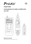
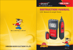
LCD Multifunction Cable Tester
User’s Manual
nd
,
2 Edition 2013
©2013 Copyright by Prokit’s Industries Co., Ltd.
Please read the safety instructions carefully before using or
maintaining the equipment
●Never expose the equipment directly in the sun.
●Never store the equipment at dusty humidity and high
temperature (over 40℃) environment.
●Battery replacement should follow specification; otherwise, it may
damage the equipment.
●Never disassemble the equipment by yourself. Maintenance or
repair should be by professional person.
●Please remove the battery from both transmitter and receiver
when storing equipment to avoid battery liquid leaked.
●Never detect live power cord by this equipment; otherwise, it may
damage equipment or injure person.
●Never connect to any equipment when thunderstorms are likely,
this may cause personal shocked.
Overview
MT-7059 LCD Multifunction Cable Tester combines transmitter,
receiver and remote unit. The large LCD display design with multi
testing function, fast test result display, and user friendly design
features easy operation and user convenience. Ideal for long
distance wire tracing, communication line status checking, weak
circuits testing, weak distribution system installation and
maintenance. Widely used in telecommunications systems,
computer networks, network monitoring and other metal wire lines
and other fields.
1
Product features:
●Large LCD display test result for easy reading and identification.
●Directly connected to Ethernet switch/ router/ PC terminal to
perform wire hunting.
●Test UTP/STP/SFTP cat.5 cat.5e cat.6, telephone wire, coaxial
cable, USB cable, 1394 cable for cable status checking (Short,
Open, Crossover, no connection) .
●Test UTP/STP/SFTP cat.5 cat.5e cat.6, telephone wire, coaxial
cable, USB cable, 1394 cable for finding cable.
●Containing RJ45/RJ11/BNC/USB/1394 and other test socket,
without complex conversion
●Power on/off and backlight display on/off selectable switching
function.
●Auxiliary lighting function
●Different sound indicated for different circuit status.
●9 tones selection for convenience use under different
environment condition.
●9V battery for power supply and low-voltage indicated function
Specification
Transmitter
Display
Tone frequency
Max. distance of
transmission
Max. distance of cable
map
Max. working current
Tone mode
Compatible connectors
Continuity test
LCD 53X25mm,with backlight
225kHz
2km
300m
≦70mA
9 adjustable tone
RJ45(8 pin)、RJ11(6 pin)、BNC、
USB、IEEE 1394
LCD (SHORT)
2
Transmitter
Max. signal voltage
Function selection
Function and faults LCD
display
Cable map indication
Shielded indication
Voltage protection
Low battery display
Battery type
Dimension (LxWxD)
Receiver
Frequency
1.5Vp-p
3 function buttons & 1 power switch
LCD display (wire map;tone;short;
no adapter;UTP;STP;low battery)
LCD (#1~#8)
LCD (#9)
AC 60V/ DC 42V
LCD (6.5V)
DC 9.0VNEDA 1604/ 6F22 DC9V ×1)
(Alkaline battery recommended)
185X80X32mm
225kHz
The max. working current
Ear jack
LED illumination
Battery type
Dimension (LxWxD)
Remote unit
Compatible connectors
Dimension (LxWxD)
≦70mA
1
2 LEDs
DC 9.0VNEDA 1604/ 6F22 DC9V ×1)
(Alkaline battery recommended)
218X46X29mm
RJ-45(8 pin)、RJ-11(6 pin)、BNC、
USB、IEEE 1394
107X30X24mm
3
Product Interface and Keypad Introduction
Instructions for product
Install DC 9V battery to transmitter then
press “ON/OFF” button, it is power on
with a long sound. LCD will showed
“TEST” then auto started wire mapping
test, if the cable is not connected to
4
transmitter and receiver, the LCD will show “NO ADAPTER”
Cable mapping test (for example: test RJ45 patch cord)
Plug in RJ45 patch cord to transmitter, and the other terminal into
remote unit, press “ON/OFF” button and push “TEST” button for
wire mapping test. If the cable with shielding (or earthed), LCD will
show “STP”; if not LCD will show “UTP”. Press “LIGHT” to turn on
backlight when you test in dark environment.
Several test results as follows may occur.
Test Result1: Short (SHORT)
If cable or connector connected
situation is short, transmitter LCD will
show “3-4” and “short” with three short
sounds.
Test Result 2: The cable did not plug in remote unit or
transmitter,
LCD will show “NO ADAPTER”:
Test Result 3: Straight
If cable or connector connected situation is good and straight, LCD
will show as following figure with one short sound.
RJ45 cable without shielding
5
RJ45 cable with shielding wire. Number
9 indicate the cable with earthed
conduct.
Test Result 4: Open
LCD will show the numbers of good connected wires as following
figure with one short sound.
Below figure indicates that “3” “6” line of RJ45 cable is open.
Test Result 5: Crossover or miss-wire
LCD will show as following figure with two short sounds.
The figure indicates that “3” “6” line of RJ45 cable is crossover.
Test Result 6: Crossover or miss-wire with open situation
LCD will show as follow figure with two short sound and displays
The picture indicates that “3” “6” line of RJ 45 cable is crossover
and “2” “7” lines are open.
6
Perform different cable mapping test (Testing result is good)
RJ45 cable
RJ11 Cable
1394 cable
BNC cable
USB cable
USB cable with shielding
USB cable without shielding
Hunting test
Plug in the target cable (RJ45, RJ11, USB, BNC, 1394) that
wanted to find, press “ON/OFF” button, power on with a long
sound then press “SCAN” button, LCD will show as following
figure.
7
Select frequency (the number showed on bottom of LCD) depends
on tested circuit (there are 9 kinds of selectable frequencies, press
“SCAN” button to change it. (Number 1 to 9 then back to 1.).
Open the battery compartment cover of receiver then install 9V
battery. Press “TEST” button, the “POWER” LED will light up, then
take the receiver and make the probe part approaching the
numerous cables and find target wire. When receiver closes to the
target cable, sound will be louder.
Extra functions
(1) Low battery indication
(2)
(3)
(4)
(5)
When the battery is low, LCD will show flash “ ” icon.
Please replace battery.
LCD backlight function
Press the LIGHT key on transmitter panel, LCD backlight will
light up, and around 10 seconds lights off automatically.
Earphone function
Please wearing earphone when perform test in noisy
environment to avoid interference.
Volume adjustment
Turn volume adjustment switch on the receiver when perform
hunting test to ensure the sound is clear for listening.
Illumination
There are 2 white LEDs on the top of receiver and the on/off
button beside earphone jack.
Packing list
1. Transmitter x 1
2. Receiver x 1
3. Remote unit x 1
7. Alligator clip adaptor cable x
1pcs
8. RJ45 adaptor cable : 1pcs
8
4. 9V Alkaline battery x 2
5. Earphone x 1
6. RJ11 Adapter cable x 1
9. User’s manual x 1
10. Carrying bag x 1
11. Color box x 1
Troubleshooting
Problem
Solution
Check battery of transmitter, if low
battery, replace a new one.
Can’t perform cable map
Confirm plug is well connected.
If above two ways can’t solve problem,
Instrument is damaged; please send it
back to us for repair.
Check battery of receiver, if low battery,
replace a new one.
Confirm transmitter is on “SCAN”
Can’t receive the tone
function.
signal for finding cable
If above two ways can’t solve problem,
Instrument is damaged; please send it
back to us for repair.
It is probable tone signal interfere with
Perform test with
telecom switching equipment signal
telecom switching
when perform cable finding test that will
equipment, can’t receive
effect testing result, you can turn telecom
the tone signal for
switching equipment power off if
finding cable
necessary.
Confirm plug is well connected.
Cable mapping result is If reinsert plug can’t solve problem,
incorrect.
Instrument is damaged; please send it
back to us for repair.
Instrument is damaged; please send it
The other problems.
back to us for repair.
9