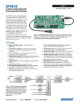
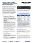
1
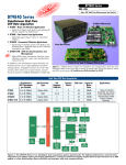
Datasheet DT9836, DT9832 & DT9832A BUS: USB Type: Simultaneous Multifunction Series High Performance Simultaneous Data Acquisition USB Modules DT9836 Series: — 6 or12 simultaneously captured analog input channels with 16-bit resolution @ 225kHz per channel. DT9832 Series: — 4 simultaneously captured analog input channels with 16-bit resolution @ 1.25MHz per channel. DT9832A Series: — 2 simultaneously captured analog input channels with 16-bit resolution @ 2.0MHz per channel. In addition to the simultaneous channels, all modules feature two deglitched waveform analog outputs, 32 digital I/O lines, two 32-bit user counter/timers, and three quadrature decoders. All functions can be synchronously triggered on the same clock. Figure 1. The High Performance Simultaneous Series modules are available in two configurations: BNC connection box and OEM embedded version. Both have 500V galvanic isolation. Simultaneous and Synchronous USB Series Simultaneous A/D Throughput per Channel Highest Signal Frequency for Measurement Signal Bandwidth D/A Channels @500 kHz Quad Decoders/ C/T 32 High Speed DIO Lines DT9836 6 or 12 ch @ 225kHz 112.5kHz >1.125MHz 0 or 2 3/2 225kHz DT9832 4 ch @ 1.25MHz 625kHz >6.25MHz 0 or 2 3/2 1.25MHz DT9832A 2 ch @ 2.0MHz 1.0MHz >10.0MHz 0 or 2 3/2 2.0MHz Applications Semiconductor Device Characterization, Nanotechnology Testing, Scientific Analysis, Drug Discovery, Automotive Testing USB 500V Isolation Barrier Simultaneous A/D up to 2.0 MHz per Channel Analog In 16-Bit D/A 16-bit A/D 16 DI 2, 32-Bit 3 Quadrature Encoders 2 16-Bit D/A 2, 4, 6 or 12 Simultaneous Channels Analog In Analog Out Output Clock Up to 500 kHz 16-bit A/D 16 DO DOUT DIN Software Triggers C/T Up to 48 MHz Ext Clocks QD Clock & Trigger Control Ext Triggers Input Clock Up to 2.0 MHz Figure 2. The DT9836 and DT9832 Series provides USB 2.0 multifunction modules for simultaneous acquisition of 2 to 12 analog inputs. Each series differs only in the number of simultaneous inputs and the throughput speed. All functions: A/D, D/A, DIO, Quad Decoder, and C/T can be synchronously triggered. For more detailed block diagrams, click here. Amplicon.com IT and Instrumentation for industry Sales: +44 (0) 1273 570 220 Website: www.amplicon.com Email: [email protected] Datasheet Simultaneous, High Accuracy Performance The High Performance Simultaneous Series provides simultaneous analog input operation. Each analog input has its own A/D converter to eliminate phase shift between channels - a problem with multiplexed architectures where all inputs share one A/D converter. As a result, this Series allows you to correlate simultaneous measurements. Precision Measurements... True 16-bit A/D at up to 2.0MHz throughput per channel for measuring multiple input signals simultaneously Designed for Low Noise ... Layer 1 12-layer PCB provides optimal grounding and shielding to maintain signal integrity No Limits ... Full simultaneous and synchronous operation of all subsystems Layer 2 Fully Protected ... 500V galvanic isolation protects your computer and maintains signal integrity High-Speed USB 2.0 ... Layer 3 USB 2.0 connector for data transfer at up to 480Mbps Layer 4 100 mm size Layer 5 Layer 6 Layer 7 Layer 8 Simultaneous Analog Inputs ... Layer 9 2, 4, 6 or 12 simultaneously sampled analog input channels Layer 10 Ultra Digital I/O ... Full digital I/O flexibility for time stamping, pattern recognition, & synchronizing with external events FullFeatured Counter/ Timers ... External Three Quadrature Control ... Decoders ... Flexible For X/Y Two 32-bit positioning counter/timers and rotation ideal for (tachos) testing applications. clocks and triggers The Simultaneous Series is available in the same package size for all models. Layer 11 Layer 12 Flexible Power Connections ... +5 V connector; a secondary +5 V connector is provided for embedded applications 2 Amplicon.com IT and Instrumentation for industry Sales: +44 (0) 1273 570 220 Website: www.amplicon.com Email: [email protected] Datasheet Selection Criteria: Nyquist and Bandwidth Limits Determine Model Choices Each model has been designed to accurately measure higher bandwidth signal components. To accurately measure 16-bit accuracy, the front-end input amplifier has a bandwidth of ten times the Nyquist limit. Below are examples of these design characteristics for each board. DT9836 Nyquist Limit N DT9836 Sampling Rate 3 dB Point dB DT9836 Signal Bandwidth Frequency 112.5kHz 225kHz >1.125MHz Figure 3. The DT9836 has a sampling rate for each channel of 225 kHz. This means that the Nyquist limit allows signal frequencies up to 112.5 kHz to be adequately measured. The analog input components have a signal bandwidth that is ten times the Nyquist limit or in this case, greater than 1.125 MHz to minimize roll-off and phase errors. DT9832 Nyquist Limit N DT9832 Sampling Rate 3 dB Point dB DT9832 Signal Bandwidth Frequency 625kHz 1.25MHz >6.25MHz Figure 4. The DT9832 has a sampling rate for each channel of 1.25 MHz. This means that the Nyquist limit allows signal frequencies up to 625 kHz to be adequately measured. The analog input components have a signal bandwidth that is ten times the Nyquist limit or in this case, greater than 6.25 MHz to minimize roll-off and phase errors. DT9832A Nyquist Limit N DT9832A Sampling Rate 3 dB Point dB DT9832A Signal Bandwidth Frequency 1.0MHz 2.0MHz >10.0MHz Figure 5. The DT9832A has a sampling rate for each channel of 2.0 MHz. This means that the Nyquist limit allows signal frequencies up to 1.0 MHz to be adequately measured. The analog input components have a signal bandwidth that is ten times the Nyquist limit or in this case, greater than 10.0 MHz to minimize roll-off and phase errors. Amplicon.com IT and Instrumentation for industry Sales: +44 (0) 1273 570 220 Website: www.amplicon.com Email: [email protected] Datasheet Figure 6. These graphs show the outstanding quality of the DT9836, DT9832, and DT9832A for all error sources... with ENOB (Effective Number Of Bits) ratings of 13.6, 13.6, and 14.1 bits respectively and an SFDR (Spurious Free Dynamic Range) of 86dB. CLK t AD Analog Input t AJ Sampled Data T/H Hold Track Hold t AD = Aperture Delay of 35 ns t AJ = Aperture Jitter (Uncertainty) of 1 ns The time between each channel (Aperture Delay Matching) is 5 ns maximum. Figure 7. The DT9836 Series features 6 or 12 independent, successive-approximation A/D converters with trackand-hold circuitry. Each converter uses a common clock and trigger for simultaneous sampling of all analog inputs at up to 225kS/s per channel. The DT9832 Series features 2 or 4 simultaneous A/D converters with sampling rates up to 2.0 MHz. Amplicon.com Figure 8. The Simultaneous Series A/D design features built-in accuracy. A maximum aperture delay of 35ns (the time that it takes the A/D to switch from track to hold mode) is well matched at 5ns across all track-and-hold circuits, virtually eliminating the channel-to-channel skew that is associated with multiplexed inputs. A maximum aperture uncertainty of 1ns (the jitter or variance in aperture delay), virtually eliminates phase noise in data. IT and Instrumentation for industry Sales: +44 (0) 1273 570 220 Website: www.amplicon.com Email: [email protected] Datasheet Overview updating the digital output lines with specified analog output channels at the D/A clock rate. You can update analog output channels at up to 500 kSamples/s. Both Series feature the following output modes: The High Performance Simultaneous Series features simultaneous analog inputs, deglitched waveform analog outputs, 32 digital input/output lines, 2 counter/timers, and 3 quadrature decoders. All these subsystems can be run synchronously. Continuous output mode – Choose this mode if you want to accurately control the period between conversions of individual output channels in the output channel list. Synchronous Operation All functions of the data acquisition modules (All A/D, D/A, DIO, Counter Timers, and Quadrature Decoders) can be simultaneously triggered internally or externally. The data can then be streamed synchronously to host memory. This can be done via external trigger or by the internal clock of the module. The synchronous operation allows all I/O data to be processed and correlated for all inputs and outputs. This is very valuable in determining the response across a device-under-test (DUT) to stimuli at the same exact instant. Simultaneous, High-Resolution Analog Inputs This Series of modules is available in various analog input channel configurations: DT9836 Series: 12-channel or 6-channel. Each analog input signal has its own analog-to-digital converter with sampling rates of up to 225kHz and 16-bit resolution. DT9832 Series: 4-channel. Each analog input signal has its own analog-to-digital converter with sampling rates of up to 1.25MHz and 16-bit resolution. DT9832A Series: 2-channel. Each analog input signal has its own analog-to-digital converter with sampling rates of up to 2.0MHz and 16-bit resolution. Closely Matched Analog Inputs The isolated analog inputs of the simultaneous series have been designed to match each other with high precision. Each input has its own separate high impedance 16bit A/D converter. The impedance has been carefully matched for each of the inputs so that one looks exactly like the other. The data acquisition board has 12layers in its make-up to adequately shield and protect each signal path etch from the high speed transitions of the digital lines. Amplicon.com Figure 9. Separate high-speed A/D converters for each input offer parallel signal acquisition with high accuracy. The slightest mismatch would result in DC and AC errors in measurement when trying to correlate readings at the same instant in time. The SFDR plot in Figure 6 gives the best indication of the match of these DC and AC characteristics. The AC dynamic performance at high switching speeds for all channels shows overall accuracy to be better than 13.6 bits. This is worst case with all errors shown in the FFT ENOB plot. This performance is beyond any other data acquisition system available. Waveform mode – Use this mode if you want to output waveforms repetitively from an output FIFO on the module, minimizing communication overhead with the host computer. If you specify only one channel in the output-channel list, you can load a waveform containing up to 128 kSamples into the output FIFO. If you specify all the analog output channels and the digital output lines in the output-channel list, you can load a waveform containing up to 24 kSamples into the output FIFO. Using waveform mode, you can update multiple channels at up to 500 kSamples/s. High-Speed, High-Resolution Analog Outputs There are 2 simultaneous16-bit analog outputs comprising separate high speed, deglitched, waveform D/A converters. This design allows highly accurate arbitrary waveforms to be generated at throughput speeds of 500kHz each. Standard waveforms such as sine, triangle, and square waves are easily produced by loading the output memory and triggering them synchronously or separately. Great care has been used in design to minimize the glitch energy for any major or minor carry. This results in extremely smooth waveforms. You can update the analog output channels as you are acquiring analog input data for gap-free simultaneous stimulus and response. In addition, you can update the digital output lines with the analog output channels at the analog output rate. Flexible Output Modes Using the Simultaneous Series, you can output a single value from a single analog output channel or multiple values from multiple analog output channels. An output channel list gives you the flexibility of updating only the analog output channels you want or Figure 10. Two deglitched, 16-bit D/A converters for pure waveform generation. High-Speed Digital I/O Lines The Simultaneous Series modules feature 32 digital I/O lines dedicated as 16 in or 16 out. The first eight digital input lines can also be used for interrupt on change. You can read all the digital input lines simultaneously with the analog input channels at the A/D clock rate. The digital input lines can also be clocked separately as the only channel in the channel-gain list at up to 225 kHz on the DT9836, 1.25 MHz on the DT9832, and 2.0 MHz on the DT9832A. For digital output operations, you can update all the digital output lines with the analog output channels at the D/A output clock rate. All lines are EMI protected to minimize interference from transient signals. IT and Instrumentation for industry Sales: +44 (0) 1273 570 220 Website: www.amplicon.com Email: [email protected] Datasheet Options for Solution Development Quick DataAcq/ Scope Ready-to-measure applications DT-Open Layers SDK Developers Kit for C Programmers DT-LV Link Access the power of our boards through LabVIEW DTx-EZ Visual Studio Development Tools DAQ Adaptor for MATLAB® Access the visualization and analysis capabilities of MATLAB with our hardware DT Measure Foundry Graphical programming, drag & drop, no code, no wires FREE Figure 11. There are many software choices available for application development. Each option offers development capability at different levels. Choose from ready-to-measure applications to full graphical programming with DTMeasure Foundry. Multifunction Counter/Timers Quadrature Decoder Flexible Clocks and Triggers All Simultaneous Series modules feature two 32-bit user counter/timers. If you wish, you can read the value of the counter/timer channels with the analog input channels and digital input lines at the A/D clock rate. The following counter/timer functions are supported: event counting, frequency measurement, pulse width measurement, and period measurement. The Quadrature Decoder module contains three quadrature decoders which allow simultaneous decoding of three quadrature encoded inputs. The quadrature decoders may be used to provide relative or absolute position or, by calculating the difference between samples, the rotational speed. Each quadrature decoder supports ‘A’, ‘B’, and ‘Index’ inputs. The index input may be used to zero out the positional count and the A and B input relationships are used to increment or decrement the positional count. Each decoder features a digital input filter that is programmable from 27ns to 7µs for the DT9836 and from 20ns to 5µs for the DT9832 and DT9832A. This unique filtering capability helps remove ringing edges and unwanted noise. For maximum flexibility, all Simultaneous Series modules provide independent clocks and triggers for the A/D and D/A subsystems. This allows you to trigger and clock the analog output subsystem synchronously with, or independent of, the analog input subsystem. Each subsystem supports an internal clock and external clock input, as well as the following trigger types: software command, analog threshold, and external digital input trigger. 3 Quadrature 2, Encoders 32-Bit QD C/T 16 DI DIN Up to 2.0 MHz Signal B DOUT Index 16 DO Figure 12. All digital functions can triggered or clocked synchronously along with the analog I/O functions. Amplicon.com Signal A Software These modules ship with the Data Acquisition OMNI CD, which includes DT-Open Layers device drivers for Windows 2000/XP, Ready-to-Measure applications that allow you to take data immediately upon setup, and an evaluation version of our test and measurement builder, DT Measure Foundry. For maximum flexibility, these modules operate under all prominent software applications, including LabVIEW, Visual Basic, MATLAB and more. These software choices allow users of all levels – from programmers to application users – the ability to access the functionality of these modules. Figure 13. A quadrature decoder takes the output signals (A, B, and Index) for the quadrature encoder as inputs and converts these signals into a numerical value that can be used to determine position, distance, velocity, and other functions. IT and Instrumentation for industry Sales: +44 (0) 1273 570 220 Website: www.amplicon.com Email: [email protected] Datasheet Flexible Packaging Configurations The Simultaneous Series modules are available in two packaging configurations: a BNC connection box and an OEM embedded version. The BNC configurations are enclosed in metal boxes with standard BNC and DSUB connectors, 2 BNCs for connecting analog outputs, and 4 BNCs for connecting external clocks and triggers. The BNC configuration ships with a +5 V galvanically isolated power supply and power cable, USB 2.0 cable, and Data Acquisition OMNI CD. The OEM configuration, ideal for embedding in test systems, provides all the functionality of the Simultaneous Series in PC-board form. This configuration ships with a USB 2.0 cable and Data Acquisition OMNI CD. Power The BNC connection box option includes a separate +5V power supply and power cable for quick setup. OEMs can purchase these options separately as EP361. A secondary power connector is also provided for OEMs to allow custom power wiring. USB 2.0 Compatibility These modules are fully compatible with USB 2.0 and USB 1.1. USB 2.0 extends the speed of connection to up to 480 Mbps. For optimal performance, it is recommended that you use the series with a USB 2.0 port. They can be used with a USB 1.1 port, but at USB 1.1 performance. 500V Galvanic Isolation Protects Your Data Computers are susceptible to groundspikes through any external port. These spikes can cause system crashes and may even cause permanent damage to your computer. These modules feature 500 Volts of galvanic isolation to protect your computer from ground-spikes and to ensure a reliable stream of data. EMI and ESD Design Criteria The simultaneous series has been designed to perform with the lowest noise characteristics. Damping resistors in series with every I/O line minimize ringing and EMI and provide current limits that protect against transient signals. Accessories for OEM Configurations For applications where you want to embed a DT9836 or DT9832/DT9832A Series module inside other equipment, use the OEM packaging configuration (no enclosure) and our optional accessories. Cross-Series Compatibility Saves Programming Time, Protects Your Investment User Manuals The Simultaneous Series includes a comprehensive user’s manual. Manuals are provided in electronic (PDF) format on the Data Acquisition OMNI CD provided with the module. You can also purchase hard copies. Technical Support As you develop your application, application engineers are available during normal business hours to discuss your requirements. Extensive information, including drivers, example code, pinouts, a searchable Knowledgebase, and much more, is available 24 hours a day on our web site at www.datatranslation.com. Support is also available from your point of purchase. Telephone support is free for the first 45 days. After that time, support is available for a small fee. Virtually all Data Translation data acquisition boards, including the Simultaneous Series, are compatible with the DT-Open Layers software standard. This means that if your application was developed with one of Data Translation’s software products, you can easily upgrade to a new Data Translation board. Little or no Click here for full specifications: Click here to see available accessories: DT9836 Series DT9836 Series DT9832 Series DT9832 Series Click here for pin assignments: Click here for full block diagrams: DT9836 Series DT9836 Series DT9832 Series DT9832 Series Amplicon.com reprogramming is needed. For example, if you are currently using a DT3016 board on a PCI bus, upgrading to a DT9836 Series module on the USB bus is simple – just load and configure the new driver and you’re done. IT and Instrumentation for industry Sales: +44 (0) 1273 570 220 Website: www.amplicon.com Email: [email protected] Datasheet DT9836, DT9832/DT9832A Ordering Summary All DT9836 and DT9832/DT9832A Series modules are shipped with a USB cable and the Data Acquisition OMNI CD, which includes DT-Open Layers-compliant device drivers for Microsoft Windows 2000/XP, an evaluation version of DT Measure Foundry. Ready-to-Measure software, and comprehensive manuals in PDF form. The EP361 (power supply) is included with the BNC box configuration. DT983X -XX Analog Input DT9836 06 = 6 single-ended channels 12 = 12 single-ended channels DT9832 04 = 4 single-ended channels DT9832A 02 = 2 single-ended channels Analog Output DT9836, DT9832, or DT9832A 0 = 0 2 = 2 configurations). EP353 — Accessory panel with 1, 37-pin DSUB con- Software The Omni CD includes: DT-Open Layers device drivers for Windows 2000/XP Evaluation copy of DT Measure Foundry test and measurement application builder for Windows 2000/XP. Quick DataAcq — ready-to-measure software application, source code included DT-LV Link to access the power of our boards through LabVIEW. DTx-EZ to access visual programming tools for Microsoft Visual Basic and Visual C++. PAK = Package Configuration OEM = Board-level embedded version for maximum flexibility (no power supply). BNC = A metal box enclosure has BNCs for analog inputs. If you select a model with analog outputs, 2 BNCs are provided for connecting analog output signals. The BNC box configuration provides 4 BNCs for connecting external clocks and triggers. (EP361 power supply and power cable included). EP353 EP361 — A +5 V power supply (included with BNC nector and 1, 26-pin signal conditioning connector for attaching analog input signals (for OEM configurations only). EP355 — Screw terminal panel for attaching analog I/O and digital I/O signals (for OEM configurations only). EP356 — Accessory panel with 2, 37-pin DSUB connectors for attaching analog output, counter/timer, trigger, clock signals, and digital I/O signals (for OEM configurations only). EP333 — Cable with two 37-pin male DSUB connectors between STP37 and EP356 or BNC box. EP360 — Cable with one 37-pin female and one 37-pin male DSUB connector between STP37 and EP353 or BNC box. STP37 — 37-pin screw terminal panel that connects to the EP356, EP353, or BNC box via an EP333 or EP360 cable. -XXX -X Accessories (Sold Separately) Free Software Downloads EP356 EP333 Data Translation now offers free downloads on the Web for: Scope — chart recording/oscilloscope function application. DAQ Adaptor for MATLAB®— software interface to MATLAB. J2 © Copyright 2006 Data Translation, Inc. All rights reserved. All trademarks are the property of their respective holders. Prices, availability, and specifications subject to change without notice. 2/2006 STP37 J3 Module Ordering Summery Board DT9836-06-2-BNC DT9836-06-2-OEM DT9836-06-0-BNC DT9836-06-0-OEM DT9836-12-2-BNC DT9836-12-2-OEM DT9836-12-0-BNC DT9836-12-0-OEM DT9832-04-2-BNC DT9832-04-2-OEM DT9832-04-0-BNC DT9832-04-0-OEM DT9832A-02-2-BNC DT9832A-02-2-OEM DT9832A-02-0-BNC DT9832A-02-0-OEM Analog In Simultaneous 6SE 6SE 6SE 6SE 12SE 12SE 12SE 12SE 4SE 4SE 4SE 4SE 2SE 2SE 2SE 2SE Analog Out Throughput Digital In Digital Out 2 2 0 0 2 2 0 0 2 2 0 0 2 2 0 0 225 kHz 225 kHz 225 kHz 225 kHz 225 kHz 225 kHz 225 kHz 225 kHz 1.25 MHz 1.25 MHz 1.25 MHz 1.25 MHz 2.0 MHz 2.0 MHz 2.0 MHz 2.0 MHz 16 16 16 16 16 16 16 16 16 16 16 16 16 16 16 16 16 16 16 16 16 16 16 16 16 16 16 16 16 16 16 16 Counter/ Timers 2 2 2 2 2 2 2 2 2 2 2 2 2 2 2 2 Quadrature Encoders 3 3 3 3 3 3 3 3 3 3 3 3 3 3 3 3 All modules feature 16-bit resolution with input ranges of +/-10, 5V. Amplicon.com IT and Instrumentation for industry Sales: +44 (0) 1273 570 220 Website: www.amplicon.com Email: [email protected] Packaging BNC Box OEM Embedded Version BNC Box OEM Embedded Version BNC Box OEM Embedded Version BNC Box OEM Embedded Version BNC Box OEM Embedded Version BNC Box OEM Embedded Version BNC Box OEM Embedded Version BNC Box OEM Embedded Version Datasheet DT9836 Series Hardware Specifications (At +25 0 C and Rated Voltage, Unless Otherwise Specified) Analog Inputs Number of inputs Resolutions Range 6 or 12 SE Simultaneous 16 bits +/-10, +/-5 V A/D Throughput Per channel Channel bandwidth 225 kS/s 2.5 MHz to -3 dB point Sample and Hold Aperture uncertainty Aperture delay Aperture match Gain match Zero match 1 ns 35 ns 5 ns +/-0.015% +/-1.5 mV System Accuracy (% of FSR) Gain=1 Bipolar Input Range Output Coding +/-0.015% +/-10 V, +/-5 V Offset binary Maximum Input Voltage without Damage Power On Power Off Input Impedance Bias Current Integral Nonlinearity Differential Nonlinearity Inherent Quantizing Error A/D Zero Drift(/ ° C) Gain Drift (of FSR/ ° C) Analog Outputs Number of DACs Resolution +/- 30 V +/-20 V 100 M , 10 pf +/-10 nA +/-0.015% +/-0.003% +/-1/2 LSB +/-25 µV/ ° C +/-50 ppm/ ° C 2 16-bits Settling Time to 0.01% of FSR 10 V Step 100 mV Step Throughput Slew Rate Glitch Energy Output Range 5 µs 2 µs 500 kS/s 10 V/µs 12 nV-s typical +/-10 V Data Coding Bipolar Output Current Output Impedance Capacitive Driver Capability Protection Against Nonlinearity Differential Nonlinearity Inherent Quantizing Error Gain Error Zero Error Gain Drift Zero Drift (Bipolar) Amplicon.com Offset Binary +/-5 mA maximum 0.1 0.004 µF Short Circuit to analog ground 1 LSB 1 LSB +/-1/2 LSB Adjustable to Zero Adjustable to Zero +/-30 ppm of FSR/ ° C +/-10 ppm of FSR/ ° C IT and Instrumentation for industry Sales: +44 (0) 1273 570 220 Website: www.amplicon.com Email: [email protected] Yes 1 LSB Datasheet DT9836 Series Hardware Specifications (At +25 0 C and Rated Voltage, Unless Otherwise Specified) - continued. Digital I/O Subsystem (All models) Number of DIO Number of Ports Logic Family Logic Sense Input Type Input Termination Input Logic Load Logic High Input Voltage Logic Low Input Voltage Logic Low Input Current Fan-out Logic High Output Voltage Logic Low Output Voltage Logic High Output Current Logic Low Output Current Interrupt on Change Clocked with the sample clock Software I/O Selectable 32 (16 in/16 out), 1 dynamic digital output 2, 16-bit LVTTL Positive true Level sensitive Inputs tied to +3.3 V with 15 k pullup resistors 1 LVTTL load 2.0 V minimum 0.8 V maximum -0.4 mA maximum 12 mA 2.0 V minimum 0.8 V maximum -12 mA maximum 12 mA maximum Yes Yes No Counter Timer* (All models) Channels Resolution 2 user counter/timers: 3 quadrature decoders 32 bits/channel External A/D and D/A Triggers (All Models) Triggering Sources: Internal External Input Type Logic Family Logic Load Input Termination Logic Low Input Voltage Logic High Input Current Logic Low input Current Software initiated Software selectable Edge sensitive LVTTL 1 LVTTL load 2.2 k pullup to +3.3 V 0.8 V maximum 25 µA maximum -0.25 mA maximum Minimum Pulse Width: Clock High Clock Low 25 ns 25 ns Triggering Modes: Single Scan Continuous Scan Triggered Scan Yes Yes Yes Onboard A/D Clocks Base Frequency Divisor Range Usable Range 36 MHz 3 to 4,294,967,295 225 kHz to 0.00838 Hz Onboard D/A Clocks Base Frequency Divisor Range Usable Range 36 MHz 3 to 4,294,967,295 500 kHz to 0.00838 Hz * Has same logic high and low voltage and current specifications as the digital I/O lines. Amplicon.com IT and Instrumentation for industry Sales: +44 (0) 1273 570 220 Website: www.amplicon.com Email: [email protected] Datasheet DT9836 Series Hardware Specifications (At +25 0 C and rated Voltage, Unless Otherwise Specified)- continued. External A/D and D/A Clocks Input Type Logic Family Logic Load Input Termination Logic High Input Voltage Logic Low Input Voltage Logic Low Input Current Oscillator Frequency Edge sensitive, rising-edge or falling-edge programmable LVTTL 1 LVTTL load 2.2 k pullup to +3.3 V 2.0 V 0.8 V 1.2 mA DC to 225 kHz maximum (A/D); DC to 500 kHz maximum D/A Minimum Pulse Width Clock High Clock Low 25 ns 25 ns Interface Characteristics Compatible Bus Interface Type Windows Plug ‘N Play OEM Board I/O Connectors Fully packaged USB 2.0 or 1.1 Bulk DT-Open Layers Drivers USB Windows 2, 68-pin connectors Enclosure with BNC and D-Sub connectors, or board-only Power Requirements +5 Volts +/-5%, @ 2 A Maximum Physical /Environmental Dimensions (OEM Embedded Version) Dimensions (BNC Box Version) Weight (OEM Embedded Version) Operating Temperature Range Storage Temperature Range Relative Humidity 190 mm x 100 mm 215.9 mm (L) x 105.9 mm (W) x 50 mm (H) 4.6 oz. -0 to +55 ° C -25 to 85 ° C to 95% non-condensing Amplicon.com IT and Instrumentation for industry Sales: +44 (0) 1273 570 220 Website: www.amplicon.com Email: [email protected]