1
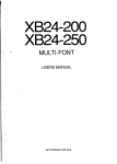
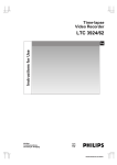
KRAMER ELECTRONICS, LTD.
Connecting To Video Devices
Video sources and output devices (such as monitors, or recorders) may be
connected to the routing switchers through the BNC type connectors located on
the back of the unit. Keep in mind that the output signal format will be that of the
input signal format.
All signal connections that use more than one cable interconnecting between
devices should be of equal timing length (example: cables between a camera
and the switcher should have the same time delay).
The rear panel of the frame is laid out in the most logical fashion possible. The
individual channels are color-coded. The white and yellow conventions, used for
the H and V sync channels, are arbitrary and these two channels are
interchangeable. Each channel can have only “H” or “V” signals – not both. All
inputs are factory set for 75 ohm termination. The sync (“H” “V”) input
terminations can be changed to 510 ohm by changing the dip switches located
on the rear panel of the router. The upper row of switches applies to the “white”
row of inputs with the lower row of switches applying to the “yellow” row.
Unused outputs do not need to be terminated.
Upper DIP
Switch
Lower DIP
Switch
Rear panel DIP
Switches
Connecting To Audio Devices
Audio sources and output devices (such as amplifiers or recorders) are
connected to the switchers through the terminal block connectors located at, and
marked, on the rear of the switcher.
VP128XL Terminal block connectors
12