1
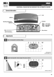
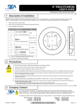
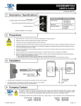
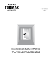
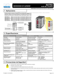
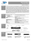
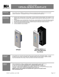
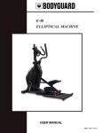
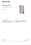
BODYMOUNT USER’S GUIDE MOUNTING BLOCK FOR BODYGUARD III 1 Description MOUNTING TEMPLATE END CAP (2) EXTRUSION 2 Specifications DESCRIPTION SPECIFICATION DIMENSIONS 12.25” X 3.00” X 2.00” (313mm X 76mm X 51mm) WEIGHT 1.4 lbs. (0.64kg) MATERIAL Black Painted Aluminum and Vinyl 3 Precautions Shut off all power going to header before attempting any wiring procedures. Maintain a clean & safe environment when working in public areas. Constantly be aware of pedestrian traffic around the door area. Always stop pedestrian traffic through the doorway when performing tests that may result in unexpected reactions by the door. ESD electrostatic discharge: Circuit boards are vulnerable to damage by electrostatic discharge. Before handling any board ensure you dissipate your body’s charge. Always check placement of all wiring before powering up to insure that moving door parts will not catch any wires and cause damage to equipment. Ensure compliance with all applicable safety standards (i.e. ANSI A156.10/19) upon completion of installation. DO NOT attempt any internal repair of the sensor. All repairs and/or component replacements must be performed by BEA, Inc. Unauthorized disassembly or repair: 1. May jeopardize personal safety and may expose one to the risk of electrical shock. 2. May adversely affect the safe and reliable performance of the product will result in a voided product warranty. 75.0090.04 20070907 Page 1 of 2 4 Installation 1 Mounting the Bodymount WIRE PASSAGE HOLE MOUNTING SCREW HOLES WIRE PASSAGE HOLES 1. Place the adhesive mounting template on the appropriate surface, depending on the application. 2. Then drill pilot holes for the wire passage and mounting screws as shown. 3. Then partially drive the two Phillips head mounting screws into the small pilot holes. 4. Remove the left endcap on the Bodymount. This will make it easier to route the wiring harness from the Bodyguard thru to the operator. 5. Then slide the extrusion over the mounting screws and using a screwdriver, finish tightening to attach the block. 2 Mounting the Bodyguard III REMOVE ENDCAP TO ATTACH SENSOR 1. Once the block is secure and the harness is routed (use two screws provided with sensor), attach the sensor to the mounting block. 2. It is necessary to remove one endcap and the two lenses to attach the sensor. 3. Finish by reinserting the lenses and center clip and replacing both the Bodyguard and Bodymount endcaps. 5 Company Contact Do not leave problems unresolved. If a satisfactory solution cannot be achieved after troubleshooting a problem, please call BEA, Inc. If you must wait for the following workday to call BEA, leave the door inoperable until satisfactory repairs can be made. Never sacrifice the safe operation of the automatic door or gate for an incomplete solution. The following numbers can be called 24 hours a day, 7 days a week. For more information, visit www.beasensors.com. US and Canada: 1-866-249-7937 Canada: 1-866-836-1863 Northeast: 1-866-836-1863 Southeast: Midwest: West: 1-800-407-4545 1-888-308-8843 1-888-419-2564 Page 2 of 2 75.0090.04 20070907