1
USERS GUIDE
PUSHPLATE MOUNTING BOXES
We open up New Horizons
PRODUCT
DESCRIPTION
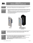
BEA’s line of pushplate hardware is expanded by its line of surface and flush mount pushplate boxes. These
boxes are made of durable ABS plastic and are made to securely mount a pushplate and a variety of
optional transmitters to activate an automatic door. Many of the boxes have an optional weather ring to give
even more weather protection to the switch. They are also designed to attractively recess the pushplate in
the housing to and to minimize vandalism from prying up the pushplate.
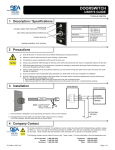
COMPONENT ID
9V Battery Clip
(1 per box, not used
on jamb sized boxes)
Pushplate Mounting Box
(4 ½” Round Surface Mount shown)
Transmitter Mounting Pin
(6 per box, not used on jamb
sized boxes)
PUSHPLATE SIZE
Jamb (4” hole spacing)
Jamb (3 ¼” hole spacing)
4 ½” Square
4 ¾” Square
4 ½” Round
6” Round
4”
•
•
•
•
•
•
SURFACE MOUNT BOX
FLUSH MOUNT BOX
10BOXJAMBSM
10BOXJAMBST
10BOX45SQSM
10BOX475SQSM
10BOX45RNDSM
10BOX6RNDSM
10BOXJAMBFM
N/A
N/A
10BOX475SQFM
10BOX45RNDFM
10BOX6RNDFM
WEATHER RING
(Optional)
N/A
N/A
N/A
10WRSQ475
10WRRND45
10WRRND6
3 ¼”
4”
JAMB
SAFETY
PRECAUTIONS
PUSHPLATE
SERIES
10PBJx
10PBJSx
10PBS45x
10PBSx
10PBR45x
10PBRx
3¼”
JAMB
4 ½”
SQUARE
4¾”
SQUARE
4½”
ROUND
6”
ROUND
Shut off all power going to the header before attempting any wiring procedures.
Maintain a clean & safe environment when working in public areas.
Constantly be aware of pedestrian traffic around the door area.
Always stop pedestrian traffic through the doorway when performing tests that may result in unexpected
reactions by the door.
Always check placement of all wiring before powering up to insure that moving door parts will not catch
any wires and cause damage to equipment.
Ensure compliance with all applicable safety standards (i.e. A NSI A156.10) upon completion of
installation.
75.0092 V4 Jan 2004 [Rev. 1/26/2004]
Page 1 of 2
MECHANICAL
INSTALLATION
1.
2.
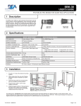
Prepare the box for installation. If the pushplate is to be hard-wired to the operator, remove either the
knockout on the back or bottom of the box. Then route the appropriate wire to the box.
Attach the box to the mounting surface. For surface mounted boxes, securely attach the box to the
surface using the corner holes. For flush mounted boxes, cut a hole in the mounting surface large enough
that the galvanized steel bracket will pass through the hole. Then use a Phillips head screwdriver to
tighten the two screws that tighten the bracket to the inside of the wall surface.
GALVANIZED MOUNTING
BRACKET
SURFACE MOUNT
3.
FLUSH MOUNT
If applicable, mount a radio frequency transmitter to the inside of the housing using either the transmitter
pins and 9V battery clip, or the Velcro tab enclosed with the transmitter kit.
Transmitter Mounting Pins
(adjust location for transmitter)
or use Velcro tab to secure
‘mini’ transmitters
9V Battery
10BOX45RSM with 10T300PB shown
COMPANY
CONTACT
If after troubleshooting a problem, a satisfactory solution cannot be achieved, please call B.E.A., Inc.
for further assistance during Eastern Standard Time at 1-800-523-2462 from 8am - 5pm.
For after-hours, call East Coast: 1-866-836-1863 or 1-800-407-4545 / Mid-West: 1-888-308-8843 /
West Coast: 1-888-419-2564. DO NOT leave any problem unresolved. If you must wait for the following
workday to call B.E.A., leave the door inoperable until satisfactory repairs can be made.
NEVER sacrifice the safe operation of the automatic door or gate for an incomplete solution.
Web: www.beasensors.com
75.0092 V4 Jan 2004 [Rev. 1/26/2004]
Page 2 of 2