1
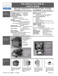
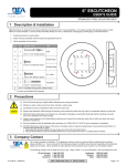
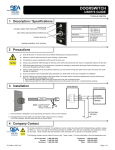
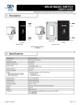
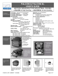
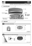
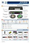
SBK-30
USER’S GUIDE
PHOTOELECTRIC BEAMS FOR GUIDE RAIL APPLICATIONS
1 Description
The SBK-30 (10.1029) is a self-contained infrared beam set that
may be used for various applications, most commonly automatic
pedestrian doors. The beams fit easily into a pre-drilled ½” hole
and are a snap fit. Wiring is by a quick disconnect cable that can
be daisy-chained up to 30’ (in 15’ increments). The beams offer
an LED indication at their back side for ease of alignment and
troubleshooting.
EMITTER
(SBK-30T)
RECEIVER
(SBK-30R)
2 Specifications
SBK30R / SBK30T BEAM
SBK30 INTERFACE MODULE
TECHNOLOGY
Active Infrared: 880nm
One SBK30 Beam Set
DETECTION MODE
Presence Detection
N/A
SUPPLY VOLTAGE
10 to 30 VDC
12 to 24 VAC/DC
CURRENT CONSUMPTION
Receiver: 15mA / Emitter: 9mA
53 mA MAX
OUTPUT CONSUMPTION
NPN Output, Light Operate
1 Relay, (NC/NO Contacts), 0-30 second adjustable hold time
OUTPUT RATING
100 mA max. Total Output Load
Rated Load:
0.3A@125VAC (NO Contacts) 0.3A@125VAC (NC Contacts)
1.0A@ 30VDC (NO Contacts) 1.0A@ 30VDC (NC Contacts)
RANGE (BEAM SEPARATION)
30 feet
N/A
OUTPUT RESPONSE TIME
1 mS
3 mS
MATERIAL
ABS Plastic & Acrylic Lense
PCB with shrink rube
CONNECTION
Molex 3-Conductor w/ 26 AWG Wire
One Beam Pair
INGRESS PROTECTION
IP65 (NEMA 4)
IP65 (NEMA 4 Enclosure)
OPERATING TEMPERATURE
-30F to +130F
-30F to +130F
WIRING
8” Wire on Beam / 15’ Extension Cable
None Included
3 Installation
1.
Pre-drill a ½” hole at the desired mounting
location.
2.
When using more than one set of beams,
alternate the beam orientation as shown
at right.
3.
Route the long cable from its termination
point to the beam mounting location.
4.
Plug the beam cable in via the snap
together connector.
5.
Install the beam into the ½” hole and press
the beam until it clicks into the opening.
Typically, the wall thickness of the drilled
material should not exceed 1/8”.
Emitter A
Emitter C
Receiver B
Receiver D
Receiver A
Receiver C
Emitter B
Emitter D
Beam A: Between 45” and 55” from floor
Beam B, C: Between 6” and 12” from any other beam
Beam D: Between 6” and 28” from floor
For sliding doors, ANSI/BHMA A156.10-2005 states the lowest beam should be between 6” (152mm) and 28” (711mm) from the floor. The
distance between the highest beam and the floor should be between 45” (1143mm) and 55” (1397mm). Other beams between the lowest and
highest should not be greater than 6” (152mm) and 12” (305mm) apart from any other beam.
75.5179.05 20080415
Page 1 of 2
4 Wiring
If using a BEA LO-Linx lockout module, simply plug
each beam into the connection point at the module.
Connection points are identified on the LO-Linx.
If using SBK30 beams directly, be sure the NPN/Light Operate output works with the door
controller. The chart below shows wire color designations for the SBK-30 TX / RX:
TX / EMITTER
RX / RECEIVER
DESCRIPTION
CABLE
TX BEAM
CABLE
RX BEAM
Ground
Black
Blue
Black
Blue
NPN/Light Operate*
White
N/A
White
Black
Red
Brown
Red
Brown
10 to 30 VDC
*Light operate means ground is provided when receiver ‘sees’ emitter.
SBK-30 Connection
To wire directly to door control, cut off connector on extension cable and strip jacket from
wires. Connect wires according to door control guidelines.
If the application requires a dry output, the SBK-30 IFB can be used. Simply plug one beam set into the IFB and wire the appropriate relay outputs
(NO or NC) per the application.
SBK-30 INTERFACE
DESCRIPTION
Red
Black
White
Green
Brown
+ 12 - 24
VAC/DC
- 12 - 24
VAC/DC
COM
NO
NC
SBK-30 IFB
5 Power ON
SBK30 BACK-SIDE LED DISPLAY
GREEN
LED
Upon powering, observe the back of the beams for LED indications.
There should be a green LED illuminated at the back-side of the
Emitter and the Receiver to indicate power ON. The Receiver
should also have an orange LED illuminated when the beam is
aligned and unobstructed.
ON = Power is applied
YELLOW
LED
ON=Beams are unobstructed
OFF=Beam Broken
RED
LED
Additionally, the SBK30 Interface LED also has indications of its
own, depending on the switch selection and SBK30 beam status.
N/A
6 Troubleshooting
SYMPTONS
PROBABLE CAUSES
CORRECTIVE ACTION
No LED’s visible at the back
side of the beam heads
No Power.
Check power supply.
Check for damaged cabling and connection points.
Beam output will not
change state
Beams are misaligned.
Faulty transmitter or receiver.
Check for yellow LED at receiver to confirm alignment. If an orange LED
can’t be obtained and green LED’s are on at TX and RX, replace receiver.
If green LED is off at TX, replace TX beam head.
7 Accessories
Jamb Cap Kit
(included with SBK30 beam set)
May be used on sliding door applications or
otherwise
Rail Mount Kit
(included with SBK30 beam set)
Used on 1.75” x 0.5” barstock-type guide rails.
InterFace Board (IFB)
(included with SBK30 beam set)
Converts an NPN output to a dry relay output
capable of powering one SBK30 Beam pair.
8 Company Contact
Do not leave problems unresolved. If a satisfactory solution cannot be achieved after troubleshooting a problem,
please call BEA, Inc. If you must wait for the following workday to call BEA, leave the door inoperable until satisfactory
repairs can be made. Never sacrifice the safe operation of the automatic door or gate for an incomplete solution.
The following numbers can be called 24 hours a day, 7 days a week. For more information, visit www.beasensors.com.
US and Canada: 1-866-249-7937
Canada: 1-866-836-1863
Northeast: 1-866-836-1863
Page 2 of 2
Southeast:
Midwest:
West:
1-800-407-4545
1-888-308-8843
1-888-419-2564
75.5179.05 20080415